King Canada 8362 User manual

1/4˝ LAMINATE TRIMMER
INSTRUCTION MANUAL
COPYRIGHT ©2005 ALL RIGHTS RESERVED BY KING CANADA INC.
MODEL: 8362
WARRANTY INFORMATION
PROOF OF PURCHASE
Please keep your dated proof of purchase for warranty and servicing purposes.
LIMITED TOOL WARRANTY
KING CANADA makes every effort to ensure that this product meets high quality and
durability standards. KING CANADA warrants to the original retail consumer a 2-year
limited warranty as of the date the product was purchased at retail and that each product
is free from defects in materials. Warranty does not apply to defects due directly or
indirectly to misuse, abuse, negligence or accidents, repairs or alterations and lack of
maintenance. KING CANADA shall in no event be liable for death, injuries to persons or
property or for incidental, special or consequential damages arising from the use of our
products. To take advantage of this warranty, the product or part must be returned for
examination by the retailer. Shipping and handling charges may apply. If a defect is found,
KING CANADA will either repair or replace the product.
PARTS DIAGRAM & PARTS LISTS
Refer to the Parts section of the King Canada web site for the most updated parts diagram
and parts list.
2-YEAR
LIMITED WARRANTY
FOR THIS LAMINATE TRIMMER
KING CANADA TOOLS
OFFERS A 2-YEAR LIMITED WARANTY
FOR NON-COMMERCIAL USE.
GENERAL AND SPECIFIC
SAFETY INSTRUCTIONS
1. KNOW YOUR TOOL
Read and understand the owners manual and labels affixed to the tool. Learn its
application and limitations as well as its specific potential hazards.
2. DON’T USE power tools in damp or wet locations or expose them to rain. Keep work
area well lit and provide adequate surrounding work space.
3. USE RIGHT TOOL.
Don’t force the tool or the attachment to do a job for which it was not designed.
4. WEAR PROPER APPAREL.
Do not wear loose clothing, gloves, neckties or jewelry (rings, watch) because they could
get caught in moving parts. Non-slip footwear is recommended. Wear protective hair
covering to contain long hair. Roll up long sleeves above the elbows.
5. MAINTAIN TOOL WITH CARE.
Keep tool clean for best and safest performance. Follow instructions for operation and
changing accessories.
6. DISCONNECT TOOLS.
Before servicing, when changing accessories or attachments.
7. AVOID ACCIDENTAL STARTING.
Make sure the switch is in the ‘’OFF’’ position before plugging in.
8. USE RECOMMENDED ACCESSORIES.
Consult the manual for recommended accessories. Follow the instructions that
accompany the accessories. The use of improper accessories may cause hazards.
9. CHECK FOR DAMAGED PARTS.
Before further use of the tool, a guard or other parts that are damaged should be
carefully checked to ensure they will operate properly and perform their intended
function. Check for alignment of moving parts, breakage of parts, mounting, and any
other conditions that may affect its operation. A guard or other parts which are damaged
should be properly repaired or replaced.
SPECIFIC RULES FOR SAFE OPERATION
1. ALWAYS SWITCH OFF AND WAIT. Wait for the bit to come to a complete stop before
any type of adjustment or maintenance.
2. Before operation,examine each bit carefully for chips, cracks or damage. Replace if
damage is found.
3. Avoid cutting into nails. Check the workpiece to make sure it’s free of nails.
4. Hold the tool in both hands with a firm, tight grip.
5. Make sure that the bit does not touch any workpiece before switching on the tool.
6. Keep in mind the rotation direction of the tool bit and the direction of the way you feed
it in.
7. Do not touch the bit right after use! It will be very hot and can burn your skin.
OPERATING INSTRUCTIONS
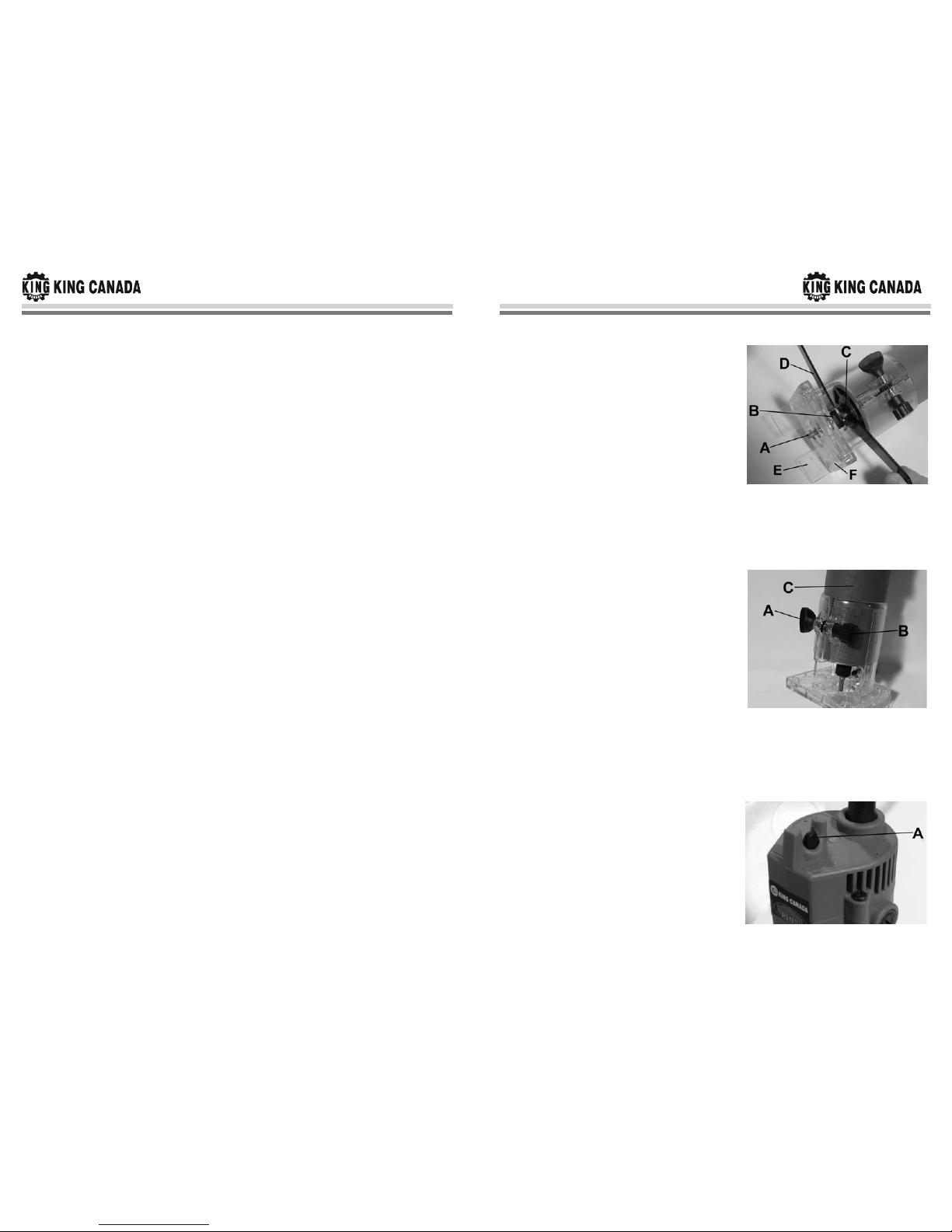
Installing or Removing Bits
Caution:Make sure the tool is switched off and
unplugged before installing or removing a bit.
Insert the bit (A) Fig.1 all the way into the collet
cone, retract the bit 1/8” out of the collet cone and
tighten the collet nut (B) securely with the two
wrenches supplied. Place small wrench (C) around
the flat of the spindle and place the other larger
wrench (D) around the collet nut to tighten. To
remove the bit, follow these instructions in reverse
order.
Caution:Never tighten the collet nut without inserting a bit, or the collet cone will break.
Adjusting Depth of Cut
Place the tool on a flat surface. Loosen lock knob
(A) Fig.2 and turn the adjustment knob (B) to move
the body up or down until the bit just touches the
flat surface. Now adjust the transparent base
upwards until you reach your desired depth of cut.
This adjustment can be done using the scale (C)
on the body. Retighten lock knob (A).
Caution:The depth of the cut adjustment should
not be more than 1/8” each pass when cutting
grooves. If you desire grooves greater than 1/8”
deep, make several passes with progressively deeper bit settings.
Turning Laminate Trimmer On/Off
To start the laminate trimmer, move the switch (A)
Fig.3 to the “ON” position. To stop, move the
switch to the “OFF” position.
Figure 1
Figure 2
Figure 3
OPERATION
Set the tool base on the workpiece to be cut without the bit making any contact. Then turn
the tool on and wait until the bit reaches full speed. Move the tool forward over the
workpiece surface, keeping the tool base flush and advancing smoothly until the cutting is
complete.
When doing edge cutting, the workpiece surface should be on the left side of the bit in the
feed direction (clockwise). When using the straight guide or the trimmer roller guide, make
sure to keep it on the right side in the feed direction. This will help keep it flush with the
side of the workpiece.
Caution:Moving the tool forward too fast may cause a poor quality cut, or damage the bit
or motor. Moving the tool forward too slowly may burn and mar the cut. The proper feed
rate will depend on the bit size, the type of workpiece and the depth of cut. It is
recommended to make a test cut on a scrap piece of wood. Verify the cut and check your
dimensions, adjust as necessary.
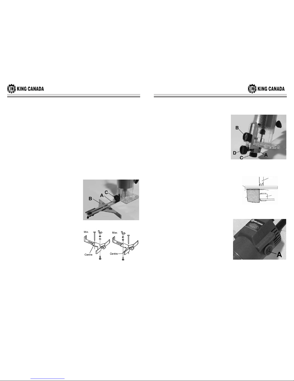
Straight Guide
The straight guide is used for straight-line cuts
when chamfering or grooving.
Attach the guide plate (A) Fig.4 to the straight
guide (B) with the bolt, flat washer, wave washer
and wing nut as shown. Remove the chip deflector
(E) Fig.1 by removing the 4 countersunk screws
which hold in place the transparent base plate (F)
Fig.1. Replace the base plate in position once the
chip deflector is removed. Attach the straight guide
assembly with the front mounted lock knob (C).
Loosen the wing nut on the straight guide and
adjust the distance between the bit and the
straight guide. At the desired distance, tighten the
wing nut securely.
When cutting, move the tool with the straight
guide flush with the side of the workpiece.
Circular Cutting
Circular cutting may be accomplished if you
assemble the straight guide and guide plate as
shown in Fig 5. (Min. 2-3/4” to 4-3/4”, Max. 4-3/4”
to 8-11/16”). Minimum radius is 2-3/4” and maximum radius is 8-11/16”. Note: Circles
between 6-3/4” and 7-5/16” in radius cannot be cut using this guide.
Align the centre hole in the straight guide with the centre of the circle to be cut. Drive a nail
less than 1/4” in diameter into the centre of the hole to secure the straight guide. Pivot the
tool around the nail in a clockwise direction.
OPERATION INSTRUCTIONS
Figure 4
Figure 5
Trimmer Roller Guide
Trimming curved cuts can be done easily with the
trimmer roller guide. The roller guide rides the
curve and assures a fine cut.
Install the trimmer roller guide (A) Fig.6 on the tool
base and lock into place with front mounted lock
knob (B). Loosen the lock knob (C) and adjust the
distance between the bit and the trimmer roller
guide by turning the adjust knob (D). At the
desired distance, tighten the lock knob to secure
the trimmer roller guide in place. When cutting,
move the tool with the guide roller riding the side
of the workpiece.
MAINTENANCE
Caution:Always make sure that the tool is
switched off and unplugged before attempting to
perform an inspection or maintenance.
Replacing Carbon Brushes
Remove and check carbon brushes regularly.
Replace when they wear down to the limit mark.
Keep the carbon brushes clean and free to slip in
the holders. Both carbon brushes should be
replaced at the same time.
Use a screwdriver to remove the brush holder
caps (A) Fig.8. Take out the worn carbon brushes,
insert new brushes and secure the brush holder
caps.
OPERATION INSTRUCTIONS
&MAINTENANCE
Figure 6
Figure 8
Figure 7
Bit
Roller guide
Laminate
Base
1/8”
Sub-straite
Table of contents
Other King Canada Laminate Trimmer manuals


