King Industrial KM-130 User manual

COPYRIGHT © 2020 ALL RIGHT RE ERVED BY KING CANADA TOOL INC.
4 PC. WET/D Y SHA PENE
ACCESSO Y KIT
INST UCTION MANUAL
MODEL: KM-130

2-YEA
LIMITED WARRANTY
FOR THI 4 PC. ACCE ORY KIT
KING CANADA TOOLS
OFFER A 2-YEAR LIMITED WARANTY
FOR NON COMMERCIAL U E.
P OOF OF PU CHASE
Please keep your dated proof of purchase for warranty and servicing purposes.
LIMITED TOOL WA ANTY
King Canada makes every effort to ensure that this product meets high quality and
durability standards. King Canada warrants to the original retail consumer a 2-year
limited warranty as of the date the product was purchased at retail and that each
product is free from defects in materials. Warranty does not apply to defects due
directly or indirectly to misuse, abuse, normal wear and tear, negligence or accidents,
repairs done by an unauthorized service center, alterations and lack of maintenance.
King Canada shall in no event be liable for death, injuries to persons or property or
for incidental, special or consequential damages arising from the use of our products.
To take advantage of this limited warranty, return the product at your expense
together with your dated proof of purchase to an authorized King Canada service
center. Contact your retailer or visit our web site at www.kingcanada.com for an
updated listing of our authorized service centers. In cooperation with our authorized
serviced center, King Canada will either repair or replace the product if any part or
parts covered under this warranty which examination proves to be defective in
workmanship or material during the warranty period.
NOTE TO USE
This instruction manual is meant to serve as a guide only. pecifications and
references are subject to change without prior notice.
KING CANADA INC. DO VAL, QUÉBEC, CANADA H9P 2Y4
www.kingcanada.com
WA ANTY INFO MATION

GETTING TO KNOW YOU
ACCESSO Y KIT & USAGE
ASSEMBLY & USAGE
Short knife jig (Fig.1)
1. lide the knife between the short knife jig clamp
(A) Fig.1, make sure the knife cutting edge is
perpendicular with the clamp.
2. Adjust the knife thickness adjusting knob (B) to
fit the thickness of the knife.
3. Tighten the clamping knob (C) to secure the knife.
4. Mark the bevel (area to sharpen) with a black
marker to allow you to see where the grinding
will occur.
5. Position the short knife jig adjustable stop (D)
onto the universal support (E) as shown. Using
the angle gauge included with your Wet/Dry harpener, adjust the universal support to
set the knife at the same angle as the knife. Loosen the adjustable stop clamping knob
(F) and twist the adjustable stop (D) for further adjustment, retighten stop clamping knob.
Make sure the heel of the bevel touches the grinding/sharpening stone.
6. Turn on Wet/Dry harpener, set the grinding/sharpening wheel rotation so the wheel turns
“AGAIN T wheel rotation” (wheel turning towards the knife). Grasp the knife handle to
control the side to side sharpening movement.
7. When the first side is done turn the knife over and sharpen the second side.
FIGU E 1
DESC IPTION & CAPACITIES
A- hort knife jig. uitable for knives having a blade length from 2-3/8” to 6-1/4”.
B- Long knife jig. uitable for knives having a blade length over 6-1/4”.
C- cissors jig. uitable for standard scissors and garden shears.
D- Axe jig. uitable for axes having a blade length up to 6-5/8”.

GETTING TO KNOW YOU
ACCESSO Y KIT & USAGE
ASSEMBLY & USAGE
Long knife jig
The long knife jig is used to sharpen in the same way as the short knife jig. Refer to
previous instructions and Fig.1.
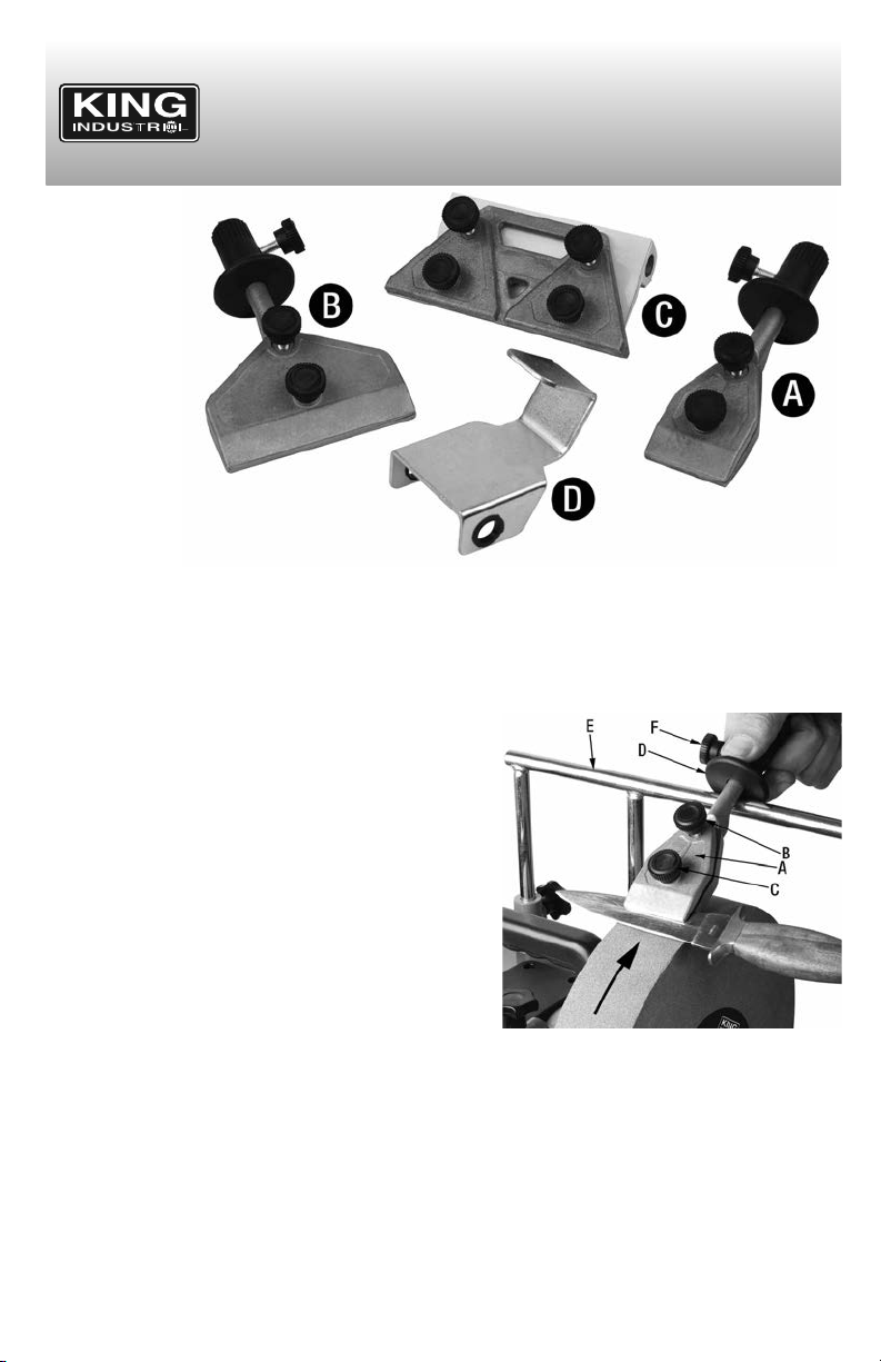
Scissors jig
The correct angle for sharpening scissors is
normally 600.
1. The support plate (A) Fig.2 gets installed onto
the universal support as shown in Fig.2. The
support plate must be set to the same scissor
blade angle (normally 600).
2. Using the angle gauge (C) Fig.2 included with
your Wet/Dry harpener, adjust the universal
support and the support plate to set it at the
same angle as the scissor blade angle.
3. Once the support plate angle is set, tighten the
support plate lock knob (B) Fig.2 to prevent it
from moving. Make sure the support plate is not
in contact with the grinding/sharpening wheel.
4. Mark the bevel (area to sharpen) of the scissor
blade with a black marker to allow you to see
were the grinding will occur.
5. lide the scissor blade between the clamp(s) (A)
Fig.3 making sure the scissor blade is
perpendicular with the clamp(s). Tighten lock
knob(s) (B) to secure scissor blade.
6. Turn on Wet/Dry harpener, set the grinding/ sharpening wheel rotation so the wheel
turns “AGAIN T wheel rotation” (wheel turning towards the scissor blade). Grasp the
scissor clamp assembly (C) Fig.3 to control the side to side sharpening movement.
7. When the first scissor blade is done, repeat steps
for the second scissor blade.
Axe jig
The bevel edge of an axe or hatchet should
generally be 25-300, this will need to be verified
using the angle guide supplied with your Wet/Dry
harpener. ome specialty axes have a larger
bevel edge (30-400).
1. lide axe jig (A) Fig.4 onto universal support (B).
FIGU E 2
FIGU E 3
FIGU E 4

GETTING TO KNOW YOU
ACCESSO Y KIT & USAGE
ASSEMBLY & USAGE
Axe jig continued...
2. Position the butt of the axe inside the axe jig as
shown in Fig.5.
3. et the axe to its bevel edge angle (25-400)
using angle guide supplied with your Wet/Dry
harpener.
4. Turn on Wet/Dry harpener, set the grinding/
sharpening wheel rotation so the wheel turns
“AGAIN T wheel rotation” (wheel turning to-
wards the axe). While sharpening, follow the
shape of the bevel edge. During grinding let the axe jig slide side to side on the universal
support so the grinding/sharpening wheel wears evenly.
General guideline
Note: User may find that “Against” rotation causes the water to run up the blade edge and
spill out onto the workbench, if this is the case “With” rotation may be more favourable.
FIGU E 5
Table of contents
Other King Industrial Tools manuals