Kinroad 150 User manual

KINROAD 150 SERVICE MANUAL VERSION 1, DEC., 2005
1
KINROAD

KINROAD 150 SERVICE MANUAL VERSION 1, DEC., 2005
2
FOREWORD
This service manual has been specially prepared to provide all the necessary information for the proper
maintenance and repair of the KINROAD 150.
The KINROAD 150 fits the needs of a wide variety of KINROAD usersabove 16 years old. Those
who will be servicing this KINROAD should carefully review this manual before performing any repair or
service.
All information, illustrations, photographs and specifications contained in the manual are based on the
latest product information available at the time of publication. Due to improvement or other changes, there
may be some discrepancies in this manual. Therefore, if newest information is requested in the future,
please contact the local distributor.
Distributor reverse the right to make production changes at any time, without notice and without incurring
any obligation to make same or similar changes to vehicles previously built or sold.

KINROAD 150 SERVICE MANUAL VERSION 1, DEC., 2005
3
CONTENTS
1. GENERAL INFORMATION -------------------------------------------------------------------------------------------------4
2. PERIODIC MAINTENANCE AND TUNE-UP PROCEDURES -----------------------------------------------------7
3. ENGINE --------------------------------------------------------------------------------------------------------------------------13
4. ELECTRIC SYSTEM ---------------------------------------------------------------------------------------------------------64
5. CHASIS --------------------------------------------------------------------------------------------------------------------------74
6. WIRING DIAGRAM -----------------------------------------------------------------------------------------------------------81

KINROAD 150 SERVICE MANUAL VERSION 1, DEC., 2005
4
1. GENERAL INFORMATION
MODEL IDENTIFICATION
FRAME NUMBER
The frame number or VIN is stamped under the seat on the frame cross member and stuck behind the seat.
ENGINE NUMBER
The engine number is located on the lower front left side of the engine cases.

KINROAD 150 SERVICE MANUAL VERSION 1, DEC., 2005
5
FUEL AND OIL RECOMMENDATIONS
Be sure to use the specified fuel and oil.
FUEL
Gasoline should SAE 90# or higher.
Unleaded gasoline is recommended.
ENGINE OIL
SAE10W-30 engine oil of high quality should be used.
BREAK-IN PROCEDURE
For the first 2 hours of riding, do not exceed 2/3 throttle.
Vary engine speed for the first 5 hours.
Never hold engine at full throttle for long periods of time.
SPECIFICATIONS
DIMENSIONS DOUBLESEAT/SINGLESEAT
Overall Length 2159mm/2075mm
Overall Width 1400mm/1235mm
Overall Height 1470mm/1400mm
Wheelbase 1499mm/1450mm
Ground Clearance 170mm/130mm
ENGINE
Type Forced air-cooled, single cylinder, 4-Stroke
Engine Capacity 150cc
Displacement 149.5cc
Bore x Stroke 57.4mm x 57.8mm
Compression Ratio 9.2:1
Max Power 7.4kw/7500rpm
Max Torque 9.5N.m/5500rpm
Fuel Type SAE 90# or above (unleaded)
Lubricate Oil SAE 10W/30
Ignition C.D.I.
Starting Electric
Spark Plug C7HSA (NGK)
Transmission AutomaticC.V.T.
Carburetor MIKUNI, BS24J
Lubrication Force & Splash

KINROAD 150 SERVICE MANUAL VERSION 1, DEC., 2005
6
CAPACITIES
Maximum Load 400lbs
Fuel Tank 7.0L
Engine Oil 850ml
Starting <5s
Climbing 25o
Battery 12V 8Ah
Head Light 12V 21W
Tail Light 12V 21W/5W
Fuse 10A
Brake Track <7 m@20mph
Top Speed 30mph
CHASSIS
Front/rear Brake Hydraulic disc, left foot control
Front Tire 21x7-10
Rear Tire 22 x 11 –10
Front Suspension Independent Dual A-Arm
Rear Suspension Swing Arm/Double Damped Shock
TIRE PRESSURE
Front 175kpa
Rear 200kpa
WEIGHT
Net Weight 170kg/105kg
** The specifications are subject to change without notice.

KINROAD 150 SERVICE MANUAL VERSION 1, DEC., 2005
PERIODICAL CHECK AND SERVICES
The maintenance intervals in the following table are based upon average riding conditions.
Riding in unusually dusty areas requires more frequent servicing.
Timeofservice
Items Initial service
(First week) Monthly Quarterly Yearly
Tire pressure/wear I I
Brake performance I I
Tightness of screws I I
Air cleaner C C I
Carburetor I A C
Spark plug C, A
Drive chain I I C, A, L
Brake fluid I
Replacement of gearbox oil I R
Chassis C, I L
Fuel switch/fuel tank C
Battery I I
Engine oil R
Valve clearance of engine A
A: adjust
C: clean
I: inspect, clean or replace if necessary.
L: lubricate
R: replace
MAINTENANCE AND TUNE-UP PROCEDURE
This section describes the servicing procedures for each item in the
Periodic Maintenance Intervals.
SPARK PLUG
Clear up the carbon around the spark plug to prevent it from dripping into
the cylinder when removing the spark plug.
Remove the spark plug
1. In general, it should be carried on after the engine is cold.

KINROAD 150 SERVICE MANUAL VERSION 1, DEC., 2005
9
2. If the spark plug is too tight to remove, spray rust inhibiter on the spark plug washer and the thread part.
Rotate the spark plug after soaking.
Clear up the filth and carbon accumulation on the spark plug with a steel brush or a blade.
Inspect the spark plug gap; in general it should be about 0.6 - 0.8 mm.
When the carbon accumulation and wear of the spark plug are too serious, replace the spark plug. Replace
a spark plug of the same specification.
TIRE PRESSURE / WEAR
Check the tire pressure every time the vehicle is ridden.
The tire pressure is very important for the stability of the ride.
BRAKE PERFORMANCE
1. Always check that there is plenty of brake fluid in the brake fluid
reservoir.
2. Check that the front/rear brake pads are in good condition
3. Check the brake rotor for abnormal wear.
AIR CLEANER
Clean the air cleaner quarterly or more often in dusty conditions.
If the air cleaner is clogged with dust, performance will be severely
decreased; even engine damages can occur. Check and clean in the
following manner.
PAPER FILTER MAINTENANCE
1. Remove the air cleaner from its housing.
2. Tap the filter on an object knocking dust from filter.
3. Replace the element if it is wrinkled or torn.
Tire pressure
Front 175 kpa
Rear 200 kpa

KINROAD 150 SERVICE MANUAL VERSION 1, DEC., 2005
10
FOAM FILTER MAINTENANCE
1. Remove the foam filter from steel cage
2. Wash in non-flammable cleaning solvent
3. Submerge in oil and squeeze to remove excess oil
4. Install the element back into the air box.
NUTS AND BOLTS IN THE CHASIS
Inspect first week and every month thereafter.
Always pay attention to the nuts and bolts. Some loosening after use is a normal situation and should be
checked regularly.
TIGHTENING TORQUE TABLE
Conventional marked bolt 8.8 marked bolt
Bolt
Diameter
(mm) N·m Kg·m lb-ft N·m Kg·m lb-ft
4 1-2 0.1-0.2 0.7-1.5 1.5-3 0.15-0.3 1.0-2.0
5 1-4 0.2-0.4 1.5-3.0 3-6 0.3-0.6 2.0-4.5
6 4-7 0.4-0.7 3.0-5.0 8-12 0.8-1.2 6.0-8.5
8 10-16 1.0-1.6 7.0-11.5 18-28 1.8-2.8 13.0-20.0
10 22-35 2.2-3.5 16.0-25.5 40-60 4.0-6.0 29.0-43.5
12 35-55 3.5-5.5 25.5-40.0 70-100 7.0-10.0 50.5-72.5
14 50-80 5.0-8.0 36.5-58.0 110-160 11.0-16.0 79.5-115.5
16 80-130 8.0-13.0 58.0-94.0 170-250 17.0-25.0 123.0-181.0
18 130-190 13.0-19.0 94.0-137.5 200-280 20.0-28.0 144.5-202.5
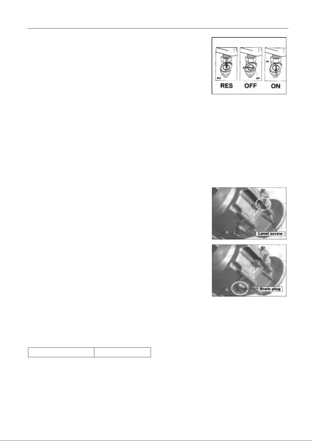
FUEL SWITCH (PETCOCK)
1. Periodically clean the petcock externally with grease remover and water.
2. Check for any leaks or seeping fuel.
3. Replace the petcock if there are any leaks found.
This vehicle has a manually operated fuel valve. There are three positions.
“ RES ” “ OFF “ “ ON “
1.Before and during cleaning, inspect the element for tears. Atorn element must be replaced.
2.Make sure the element is seated properly and no foreign material can pass by it

KINROAD 150 SERVICE MANUAL VERSION 1, DEC., 2005
11
“ON” position
The normal operating position for the fuel valve lever is the “ON” position.
In this position, fuel will flow to the carburetor.
“RES” position
If the fuel lever in the fuel tank becomes too low for the engine to operate
with the fuel valve lever in the “ON” position, turn the lever to the “RES”
position to use the reserve fuel supply, and refuel as soon as possible.
"OFF" position
The closing position for the fuel valve lever is the "OFF" position.
When the vehicle is not in use, always make sure the petcock is in the "OFF" position
FINAL GEAR OIL
Inspect monthly and change quarterly.
1. To check the oil level, remove the level screw on the left rear engine
case.
2. To drain oil, remove the drain plug at the rear bottom of the engine
case. It is recommended to warm the engine for 10 minutes or more
before draining final gear oil.
NOTE:
Mobil 85w/90 gear oil is recommended in the final drive case. However, in extreme cold weather conditions,
you may experience the vehicle to be hard to start. It is then advised to use lighter viscosity oil, such as 75
wt, or equivalent motorcycle transmission fluid.
Gear Oil Capacity 0.2L 85w/90

KINROAD 150 SERVICE MANUAL VERSION 1, DEC., 2005
12
ENGINE OIL
Inspect every time before riding. Replace monthly.
1. Remove the drain plug from the left side bottom of the engine. Drain
into oil pan for disposal.
2. Remove the large cap on the left bottom of the engine and remove
the screen.
3. Wash the screen with cleaning solvent and refit, making sure the
O-ring is still in good conditions.
4. Refill the engine with SAE10W/30SF engine oil and run for 5 minutes.
5. Check oil level on the filler cap stick to assure proper level.
6. The cap needs to be screwed in to check.
CHASSIS
1. Grease chassis bushings and bearings with grease quarterly to assure smooth operation and extended
life of the bushings and the components.
2. If used in extreme wet and muddy conditions or dusty conditions, it is recommended to service more
often.

KINROAD 150 SERVICE MANUAL VERSION 1, DEC., 2005
13
3. ENIGNE
CYLINDER
CYLINDER REMOVAL
The removal can be done on the vehicle body.
Remove cylinder head.
Remove cylinder.
Remove cylinder gasket, bolts.
Erase cylinder gasket.
CYLINDER INNER WALL WEAR INSPECTION
Use a bore diameter dial gauge to measure the degree of wear.
The measuring point is divided into three
sectional planes in the axial direction: upper,
middle, lower; measure every plane each
time on the mutually perpendicular directions
(X, Y). The least measured dimension is the
cylinder bore; the data measured at the most
upper position is the largest diameter, and
the lower position is the smallest diameter. At the same cross section, measure the difference of diameter
between two points mutually perpendicular, which is the circularity of the cylinder.
In the situation without a dial gauge, a feeler gauge can be used to make relativity measurement. Put a new
piston into the cylinder, and use the feeler gauge to measure the gap between the piston skirt and the
cylinder wall, and then figure out the abrasion loss of the cylinder.
If the circularity of the cylinder exceeds the limit, a cylinder-reboring machine should be used to re-bore the
1. Do not damage the bond area of the cylinder.
2. Do not drop sundries, such as cylinder gasket material into the crankcase.
zIn order to make the measuring point perpendicular with the bore axis of the cylinder,
and to ensure the precision of the measurement, the bar of the gauge can be slightly
swung in the direction of the gauge bar, and take the smallest reading number as the
result.

KINROAD 150 SERVICE MANUAL VERSION 1, DEC., 2005
14
cylinder, and to enlarge its diameter by 0.50mm or 1.00mm, then fit the piston and piston ring whose sizes
are also enlarged. If the wear is too severe and cannot be reworked, a new cylinder should be installed.
Cylinder bore 57.4mm
Cylindricity 0.05mm
Circularity 0.05mm
CRANK CONNECTING ROD MECHANISM
PISTON SET
PISTON PIN INSPECTION AND SERVICING
Insert the piston pin horizontally into the pinhole of piston, and inspect the clearance between piston and
piston pin.
If the free play is too much, the worn condition of piston pin and the pinhole of piston must be inspected
respectively.
Measuring the external diameter of piston pin.
If the result is less than service limit, it should be replaced.
After replacement, the clearance between piston pin and the pinhole of piston must comply with the
requirement.
Measure the inner diameter of piston pin.
If the result is more than service limit, it should be replaced.
After replacement, the clearance between the pinhole of piston and piston pin must be sure to comply with
the requirement.
PISTON RINGS INSPECTION AND SERVICING
Inspect if there is a flaw, serious wear, or serious conglutination on the piston ring. If there is, it should be
replace.
If the piston ring’s lateral clearance and notch clearance are too large or too small, malfunction may be
caused. So it must be measured.
Measure the clearance of piston ring in the piston ring groove. This clearance is the piston ring’s lateral
Service limit 0.02 mm
Service limit 14.96 mm
Service limit 15.04 mm

KINROAD 150 SERVICE MANUAL VERSION 1, DEC., 2005
15
clearance.
CONNECTING ROD END INSPECTION
Put the piston ring and bearing into the connecting rod end; inspect the degree of tightness of the piston pin
in connecting rod end.
Measure the inner diameter of the connecting rod end.
Service limit 15.06 mm
When the abrasion of the bore exceeds the limitation, it should be replaced.
PISTON RING SET
Before setting up, apply oil on every piston ring, and then enlarge piston rings. AT the same time cover
them on the piston and move forwards gradually until piston rings fall into the ring groove.
PISTON RING INSTALLATION
Remove the gasket attached to the crankcase.
Mount piston onto the small end of the connecting rod.
Mounting piston pin and piston pin clip.
First ring 0.09 mm
Second ring 0.09 mm
zThe top of the piston with “IN” mark should be mounted towards the direction of the inlet port
(If the mark is “EX”, it should be mounted towards the direction of the exhaust port.)
zApply oil on the piston pin to lubricate it.
zCover a piece of cloth on the crankcase port to avoid the piston pin clip from dropping into the
crankcase.

KINROAD 150 SERVICE MANUAL VERSION 1, DEC., 2005
16
CRANK CONNECTING ROD SET
The connecting rod is the component that link piston and crank.
The picture shows the structure and assembly relations of the crank connecting rod component.
CRANKCASE AND CRANKSHAFT REMOVAL
Take the following procedures when removing the crankcase and
crankshaft.
Remove the engine.
Remove the cylinder cover
Remove the cylinder
Remove the piston
Remove the drive plate and the driven plate.
Remove the AC generator.
Remove the starting motor.
Remove the oil pump.
Then remove the cam chain tensioner bolt. Remove the cam chain
tensioner.

KINROAD 150 SERVICE MANUAL VERSION 1, DEC., 2005
17
Use special tools to remove the starting driven gear.
Remove the crankcase positioning bolts.
Separate the right crankcase and the left crankcase.
Remove the gasket and the dowel pins.
Remove the crankshaft from the crankcase.
Take out the cam chain.
Clean up the gasket on the crankcase joint face. Pay attention not to
damage the joint face.
Remove the oil seal from the left crankcase.
The joint face cannot be damaged.

KINROAD 150 SERVICE MANUAL VERSION 1, DEC., 2005
18
Remove the oil seal from the right crankcase.
CRANKSHAFT AND CRANKCASE INSPECTION
Replace the whole set of the crankshaft if serious wear is found while inspecting.
Measure the axial clearance of the big end of the connecting rod.
When measuring, make one side of the connecting rod big end close to the crank, and insert the feeler
gauge between the other side and the crank and get the correct end play.
Measure the radial (X, Y) clearance of the big end of the con’rod.
Measure the main shaft jump of the crankshaft.
If the crank jump is too much, it will cause the engine to shake abnormally, and shorten the life of the engine.
So it must be examined carefully when inspecting.
0.10mm (A = 90)
Service limit
0.10mm (B = 105)
Examine if there is any looseness, or unusual sound when the crank journal bearing turns. If there is, the
whole set should be replaced.
Inspect if the joint face of the crankcase is smooth and clean, and notice if it will affect the sealing
performance between the left and right crankcase while reassembling.
After the above inspection, use oilstone to furnish the crankcase if it has some surface damage. Replace
cover if damage is too severe.
Service limit 0.55 mm
Service limit 0.05 mm
zThe right and left crankcase axle hole must be concentric, so generally they must be replaced at
the same time.

KINROAD 150 SERVICE MANUAL VERSION 1, DEC., 2005
19
CRANKSHAFT AND CRANKCASE INSTALLATION
Mount the crankcase oil seal.
Put the cam chain into the left crankcase.
Put the crankshaft into the left crankcase.
Mount the new dowel pins and gasket on the left crankcase.
Join the right crankcase and the left crankcase together
Tighten the crankcase positioning bolts.
Mount the starting driven gear.
Mount the cam chain tensioner.
Mount the new O-ring on the cam chain tensioner bolt.
Apply some oil on the O-ring.
Tighten the cam chain tensioner bolt.
Tightening torque 1.98 lbs·m
zPay attention to avoid the cam chain damaging the oil seal.
zThe o-ring must be mounted in the groove.

KINROAD 150 SERVICE MANUAL VERSION 1, DEC., 2005
20
VALVE MECHANISM INSPECTION AND SERVICING
The picture shows the common valve train of a four-stroke engine. This is a kind of overhead valve; its
intake port, exhaust port, camshaft are all located in the cylinder head; the valve bottoms up over the
combustion chamber.
GENERAL INTRODUCTION
The four-stroke engine completes its four stroke with one piston stroke.
Intake stroke
Compression stroke
Expansion stroke
Exhaust stroke
VALVE CLEARANCE ADJUSTMENT
Valve clearance is an important technical parameter.
Make sure that the valve can close tightly under any conditions, especially when the engine is overheated;
there must be certain clearance kept when the valve is in the cold condition. This clearance is called valve
clearance. When the engine is running, the valve clearance should be neither too big, nor too small. So the
valve clearance adjustment is an important procedure in the valve maintenance.
Remove the cylinder head cover.
zInspection and adjustment must be done in cold
conditions (below 35°C).

KINROAD 150 SERVICE MANUAL VERSION 1, DEC., 2005
21
Turn the cooling fan clockwise until the mark of the timing drive
sprocket on the camshaft is at top dead center, and the "T" symbol
(or other mark) of the magneto flywheel aligns with the crankcase
mark.
When adjusting, loosen the lock nuts; adjust the bolts with a
valve-adjusting wrench; if turning clockwise, the valve clearance
decreases, and if turning counterclockwise, the valve clearance
increases. Then, put a feeler gauge with specific size between valve
and rocker to check for correct clearance.
Take out the feeler gauge; tighten the lock nuts, and then inspect the
valve clearance again.
Valve clearance 0.06~0.07 mm
CAMSHAFT
The camshaft is a main driving unit of the valve train. There are the air inlet cam, the exhaust cam, and the
cam journal on the shaft. It controls the intake and exhaust valve to open and close at the correct time. The
camshaft wear will affect engine performance and cause excessive noise
CAMSHAFT REMOVAL
Loosen valve cover bolts and remove cover.
Remove the cam chain tensioner screw, and remove the O-ring.
Tighten the cam chain tensioner-adjusting bolt clockwise.
zThe crankshaft should co-rotate; otherwise the
exhaust port may not be adjusted.
zSometimes when tightening the lock nuts,
it will change the clearance. So it must be
rechecked for the proper clearance.
Other Kinroad Offroad Vehicle manuals
Popular Offroad Vehicle manuals by other brands

BRP
BRP can-am Defender X mr 2023 Series Operator's guide

Hammerhead
Hammerhead Rave 150 HH150 Operator's manual

BOMBARDIER
BOMBARDIER Citation LS 1988 Operator's manual

Yamaha
Yamaha SR10RE Operator's manual

FEISHEN
FEISHEN K550ATV EEC 4x4 owner's manual

CROSSRUNNER
CROSSRUNNER All Terrain Vehicle 250 Reassembly manual