Kirkland Signature 2327691 Product information sheet

FREESTANDING OUTDOOR ISLAND GRILL
Installation Instructions and Use & Care Guide
Missing Parts / Questions / Issues
For assistance with parts, assembly, installation, etc. Please call: 1-866-984-7455
Languages spoken: English, French, Spanish 8 a.m.-5 p.m., PST. Monday-Friday.
Costco Member Service Number: 1-800-774-2678
Operating hours 8 a.m.-5 p.m., PST. Monday-Friday.
www.Costco.com
19001002A0
IMPORTANT, RETAIN FOR FUTURE REFERENCE: READ CAREFULLY.
IMPORTANT, CONSERVEZ-LE POUR RÉFÉRENCE FUTURE : LISEZ ATTENTIVEMENT.
860-0031 (LP) 870-0031 (NG)
ITM. / ART. 2327691
FOR OUTDOOR USE ONLY. NOT FOR COMMERCIAL USE.
POUR UN USAGE EXTÉRIEUR UNIQUEMENT. PAS POUR UN USAGE COMMERCIAL.
GRIL ÎLOT EXTÉRIEUR AUTOPORTANT
Instructions d'installation et utilisation & Guide d'entretien
Pièces manquantes / Questions / Problèmes
Pour toute assistance concernant les pièces, le montage, l'installation, etc. Veuillez appeler : 1-866-984-7455
Langues parlées : Anglais, français, espagnol 8 heures - 17 heures, PST. Du lundi au vendredi.
Numéro de service aux membres de Costco : 1-800-774-2678
Heures d'ouverture : 8 h à 17 h, heure normale du Pacifique. Du lundi au vendredi.
www.Costco.com

TABLE OF CONTENTS
OUTDOOR GRILL SAFETY…………………………..…………3
INSTALLATION REQUIREMENTS…………………………....5
Product Dimensions…………………………………..……….…6
Gas Supply Requirements………………………………………7
Gas Connection Requirements………………………..……..…7
Gas Connection ..…..……………………………..……………9
GAS CONVERSION……………………………….............…...10
Tools and Parts for Gas Conversion …………………......…...10
Conversion from LP Gas to Natural Gas……….………......….11
Gas Connection .……………………..............……………15
Checking and Adjusting Burners………………….………….…17
OUTDOOR GRILL USE …………………….…….……………18
Using Your Outdoor Grill ……………………….…………….…18
Using Your Top Sear Burner……………………………………20
Using Your Griddle Burner…...………………….………………21
Using Your Side Burner………………………….………………22
TIPS FOR OUTDOOR GRILLING ……………..……………...23
Cooking Methods ………………….…………………………….23
OUTDOOR GRILL CARE ………………………………...……24
Replacing the Igniter Battery …….……………………..……....24
General Cleaning ……………………………………….….....…24
ADJUSTMENT OF GRILL DOORS…………...…………….…26
TROUBLESHOOTING ...........................................................27
ASSISTANCE …………………………………………….…..…27
Accessories………………………………………………...……..27
WARRANTY ……………………………………….…………….28
PACKAGE PARTS LIST …....................................................57
ASSEMBLY INSTRUCTIONS .…………………....…….……60
REPLACEMENT PARTS………………………………...……75
2
DANGER
If you smell gas:
1. Shut off gas to the appliance.
2. Extinguish any open flame.
3. Open lid.
4. If odor continues, keep away from
the appliance and immediately call
your gas supplier or your fire
department.
WARNING
1. Do not store or use gasoline or
other flammable liquids or vapors in
the vicinity of this or any other
appliance.
2. An LP cylinder not connected for
use shall not be stored in the
vicinity of this or any other
appliance.
TABLE DES MATIÈRES
SÉCURITÉ DES GRILS EXTÉRIEURS .…………..…………30
EXIGENCES D'INSTALLATION…………………………....32
Dimensions du produit .……………………………..……….…33
Exigences en matière d'alimentation en gaz ….………………34
Exigences en matière de raccordement au gaz …..……..…34
Effectuer le raccordement au gaz ………………..……………36
CONVERSION AU GAZ ……………………….............…...37
Outils et pièces pour la conversion au gaz ……………….....37
Conversion du gaz GPL au gaz naturel …….………......….38
Effectuer le raccordement au gaz ……………………......……42
Vérification et réglage des brûleurs …………….………….…44
UTILISATION SUR UN GRIL EXTÉRIEUR …….……………45
Utilisation de votre gril d'extérieur .…………….…………….…45
Utilisation de votre brûleur Top Sear ..…………………………47
Utilisation de votre brûleur de gril ..…………….………………48
Utilisation de votre brûleur latéral ….………….………………49
CONSEILS POUR LES GRILLADES EN PLEIN AIR ……...50
Méthodes de cuisson ....………….…………………………….50
ENTRETIEN DU GRIL EXTÉRIEUR ……………..……...……51
Remplacement de la pile de l'allumeur ………………..……....51
Nettoyage général .…………………………………….….....…51
RÉGLAGE DES PORTES GRILLES ….…...…………….…53
DÉPANNAGE ...........................................................54
ASSISTANCE …………………………………………….…..…54
Accessories………………………………………………...……..54
GARANTIE ……………………………………….…………….55
PAQUETLISTE DE PIÈCES ……………………………..57
INSTRUCTIONS DE MONTAGE……………....……….…60
PIÈCES DE RECHANGE………………………………...……75

3
OUTDOOR GRILL SAFETY
IMPORTANT: This grill is manufactured for outdoor use only. It is the responsibility of the installer to comply with the
minimum installation clearances specified on the model/serial rating plate. The model/serial rating plate for freestanding
models can be found on the left-hand cabinet door.
In the State of Massachusetts, the following installation instructions apply:
◼Installations and repairs must be performed by a qualified or licensed contractor, plumber, or gasfitter qualified or
licensed by the State of Massachusetts.
◼If using a ball valve, it shall be a T-handle type.
◼A flexible gas connector, when used, must not exceed 91.44 cm / 3 feet.
CALIFORNIA RESIDENTS ONLY - WARNING:
Fuels used in liquefied propane gas appliances, and the products of combustion of such fuels, can expose
you to chemicals including benzene, which is known to the State of California to cause cancer and
reproductive harm.
For more information, go to: www.P65Warnings.ca.gov.

WARNING: To reduce the risk of fire, electrical shock,
injury to persons, or damage when using the outdoor cooking
gas appliance, follow basic precautions, including the following:
◼Do not install portable or built-in outdoor cooking gas
appliances in or on a recreational vehicle, portable trailer,
boat or in any other moving installation.
◼Always maintain minimum clearances from combustible
construction, see “Location Requirements” section.
◼The outdoor cooking gas appliance shall not be located
under overhead unprotected combustible construction.
◼This outdoor cooking gas appliance shall be used only
outdoors and shall not be used in a building, garage, or
any other enclosed area.
◼Keep any electrical supply cord and fuel supply hose away
from any heated surfaces.
◼Keep outdoor cooking gas appliance area clear and free
from combustible material, gasoline and other flammable
vapors and liquids.
◼Do not obstruct the flow of combustion and ventilation air.
Keep the ventilation openings of the cylinder enclosure
free and clear from debris.
◼Open the cabinet door and inspect the gas cylinder supply
hose before each use of the outdoor cooking gas
appliance. If the hose shows excessive abrasion or wear,
or is cut, it MUST be replaced before using the outdoor
cooking gas appliance. Contact your dealer and use only
replacement hoses specified for use with the outdoor
cooking gas appliance.
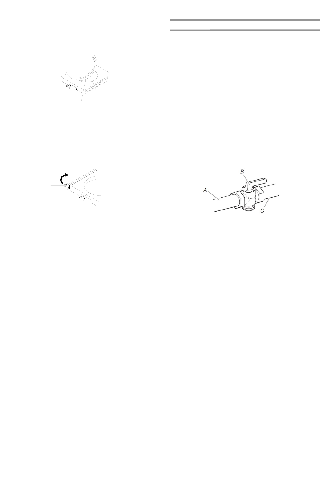
◼Visually check the burner
flames. They should be blue.
Slight yellow tipping is normal
for LP gas. The flames should
be approximately 2.54 cm / 1 in high.
◼Check and clean burner/venturi tube for insects and insect
nest. A clogged tube can lead to fire under the outdoor
cooking gas appliance.
IMPORTANT SAFETY INSTRUCTIONS
◼The LP gas supply cylinder to be used must be:
- Constructed and marked in accordance with the
Specification for LP Gas cylinders of the U.S.
Department of Transportation (DOT) or the National
Standard of Canada, CAN/CSA-b339, Cylinders,
Spheres, and Tubes for Transportation of Dangerous
Goods and Commission.
- Provided with a listed overfilling prevention device.
- Provided with a cylinder connection device compatible
with the connection for outdoor cooking gas appliances.
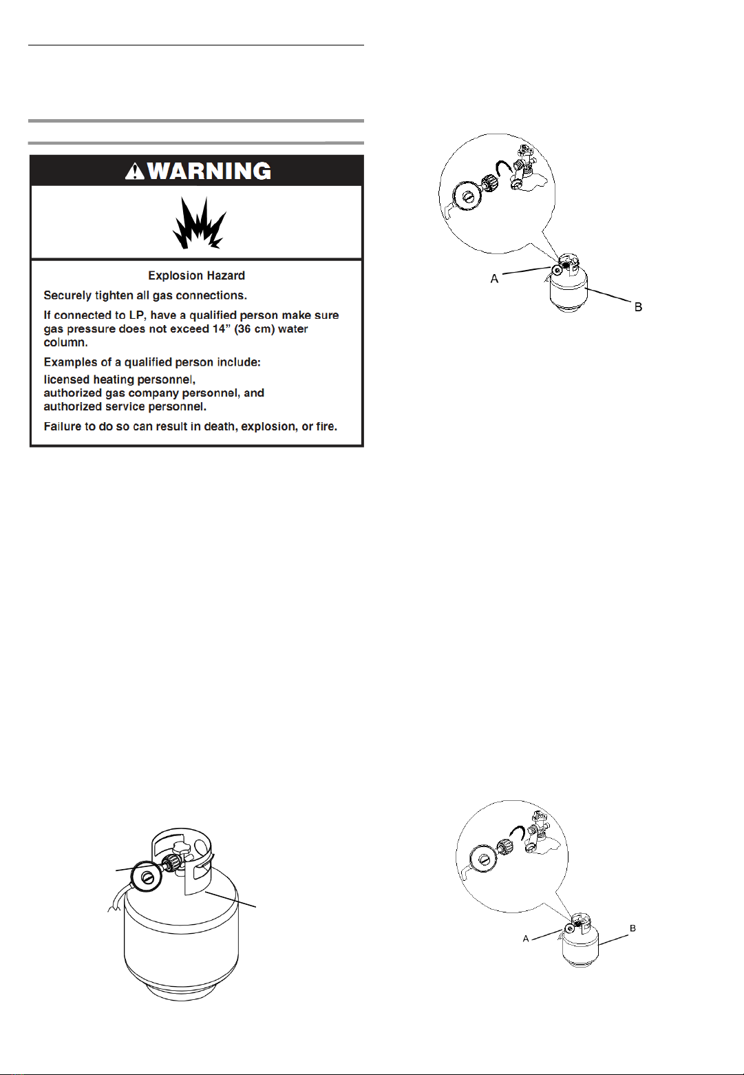
◼Always check connections for leaks each time you connect
and disconnect the LP gas supply cylinder. See
“Installation Instructions” section.
◼When the outdoor cooking gas appliance is not in use, the
gas must be turned off at the supply cylinder.
◼Storage of an outdoor cooking gas appliance indoors is
permissible only if the cylinder is disconnected and
removed from the outdoor cooking gas appliance.
◼Cylinders must be stored outdoors and out of the reach of
children and must not be stored in a building, garage, or
any other enclosed area.
◼The pressure regulator and hose assembly supplied with
the outdoor cooking gas appliance must be used. A
replacement pressure regulator and hose assembly
specific to your model is available from your outdoor
cooking gas appliance dealer.
◼Gas cylinder must include a collar to protect the cylinder
valve.
◼For appliances designed to use a CGA791 connection:
Place a dust cap on cylinder valve outlet whenever the
cylinder is not in use. Only install the type of dust cap on
the cylinder valve outlet that is provided with the cylinder
valve. Other types of caps or plugs may result in leakage
of propane.
If the following information is not followed exactly, a fire causing
death or serious injury may occur.
◼Do not store a spare LP gas cylinder under or near this
outdoor cooking gas appliance.
◼Never fill the cylinder beyond 80 percent full.
SAVE THESE INSTRUCTIONS
4
2.54 cm
/ 1 in

INSTALLATION REQUIREMENTS
Location Requirements
Select a location that provides minimum exposure to wind and
traffic paths. The location should be away from strong draft
areas.
Do not obstruct flow of combustion and ventilation air.
Clearance to combustible construction for grill:
◼A minimum of 91.44 cm / 36 in must be maintained
between the front of the grill hood, sides, and back of the
grill and any combustible construction.
◼A 91.44 cm / 36 in minimum clearance must also be
maintained below the cooking surface, and the grill shall
not be used under overhead combustible construction.
5

90.2 cm / 35.5 in
INSTALLATION REQUIREMENTS
Production Dimensions
The model/serial number rating plate is located on the inside of
the left cabinet door. See the following illustration.
A
A. Model/serial number plate
6

Observe all governing codes and ordinances.
IMPORTANT: This installation must conform with all local
codes and ordinances. In the absence of local codes,
installationmust conform with either the National Fuel Gas
Code, ANSI Z223.1/NFPA54,Natural Gas and Propane
InstallationCode, CSA B149.1, Propane Storage And Handling
Code, B149.2, or the Standard for Recreational Vehicles, ANSI
A119.2/NFPA 1192 and CSA Z240 RV Series Recreational
Vehicle Code as applicable.
IMPORTANT: Grill must be connected to a regulated gas
supply. Refer to the model/serial rating plate for information on
the type of gas that can be used. If this information does not
agree with the type of gas available,check with your local gas
supplier.
Gas Conversion:
No attempt shall be made to convert the grill from the gas
specified on the model/serial rating plate for use with a different
gas type without consulting the serving gas supplier. The
conversion kit supplied with the grill must be used. See “Gas
Conversions” section for instructions.
Gas Pressure Regulator
The gas pressure regulator supplied with this grill must be used.
The inlet (supply) pressure to the regulator should be as follows
for proper operation:
LP Gas:
Operating pressure: 11" WCP
Inlet (supply) pressure: 11" to 14" WCP
Natural Gas:
Operating pressure: 4" WCP
Inlet (supply) pressure: 7" to 14" WCP maximum.
Contact local gas supplier if you are not sure about the inlet
(supply) pressure.
Gas Supply Requirements Gas Supply Line Pressure Testing
Testing above 3.5 kPa / 1/2 psi. or 14" WCP (gauge):
The grill and its individual shutoff valve must be disconnected
from the gas supply piping system during any pressure testing
of that systemat test pressures greater than 3.5 kPa / 1/2 psi.
Testing below 3.5 kPa / 1/2 psi. or 14" WCP (gauge) or
lower:
The grill must be isolatedfrom the gas supplypiping system by
closing its individual manual shutoff valve during any pressure
testing of the gas supply piping system at test pressures equal
to or less than 3.5 kPa / 1/2 psi.
Gas Connection Requirements
9.07 kg (20lb) Propane Tank
This grill is equipped for use with a 9.07 kg (20lb) propane tank
(not supplied). A gas pressure regulator/hose assembly is
supplied.
Any brand of 9.07 kg (20lb) propane tank is acceptable for use
with the grill, provided that it is compatible with the grill’s
retention means (tank tray included).
It is also design-certified by CSA International for local LP gas
supply or for Natural Gas with appropriate conversion.
A. Gas pressure regulator/hose assembly
A
A. Tank tray locking bracket
A
The 9.07 kg (20lb) propane tank must be mounted and
secured.
Door Style Tank Tray
1. Open cabinet door.
2. Slide the tank tray lockingbracket counterclockwise 90º
and pull out the tray
7

Natural Gas Conversion
Conversion must be made by a qualified gas technician.The
qualified Natural Gas technician shall provide the Natural Gas
supply to the selectedgrill locationin accordance with the
National Fuel Gas Code ANSI Z223.1/NFPA 54 - latest edition,
and local codes.For conversion to Natural Gas, the Natural
Gas Conversion Kit supplied with the grill (on some models) or
the Natural Gas ConversionKit Part Number 710-0003 must be
used. See “Assistance” section for information on ordering.
IMPORTANT: The gas installation must conform with local
codes, or in the absence of local codes, with the National Fuel
Gas Code, ANSI Z223.1/NFPA 54 - latest edition.
Follow instructions for converting to Natural Gas in the “Gas
Conversions” section of this manual or the instructions supplied
with Natural Gas ConversionKit Part Number 710-0003.
The gas supply line shall be equipped with an approved shutoff
valve. This valve should be located at the same area as the grill
and should be in a locationthat allows ease of opening and
closing. Do not block access to the shutoff valve. The valve is
for turning on or shutting off gas to the grill.
A. Gas supply line
B. Shutoff valve “open” position
C. To grill
AB
C
A. Locking screw
B. Bottom collar
C. Mounting hole
5. Slide the drawer with the 9.07 kg (20lb) propane tank back
into the cabinet. Turn the tank tray locking bracket
clockwise 90º to tighten.
A
A. Tank tray lockingbracket
3. Place the 9.07 kg (20lb) propane tank bottom collar into
the mounting hole in the tank tray.
4. Tighten the locking screw against the bottom collar of the
9.07 kg (20lb) LP gas fuel tank to secure.
8

NOTE: If grill is to be converted to Natural Gas, follow
instructions in the “Gas Conversions” section.
9.07 kg (20lb) Propane Tank
LP Gas:
IMPORTANT: A 9.07 kg (20lb) propane tank must be
purchased separately.
IMPORTANT: The gas pressure regulator/hose assembly
supplied with the grill must be used. Replacement gas pressure
regulator/hoseassembly specific to your model is available
from your outdoor grill dealer.
To Connect the 9.07 kg (20lb) Propane Tank:
1. Check that the 9.07 kg (20lb) propane tank is in the “OFF”
position. If not, turn the valve clockwise until it stops.
2. Check that the 9.07 kg (20lb) propane tank valve has the
proper type-1 external male thread connectionsper ANSI
Z21.81.
3. Check that the burner control knobs are in the “OFF”
position.
4. Remove any debris and inspect the valve connections,
port, and gas pressure regulator/hoseassembly for
damage.
NOTE: Always keep the propane tank at 90°(upright)
orientation to provide vapor withdrawal.
Gas Connection 5. Using your hand, turn the gas pressure regulator/hose
assembly clockwise to connectto the 9.07 kg (20lb) LP
gas fuel tank as shown.
Hand tighten only. Use of a wrench could damage the
quick coupling nut.
A. Gas pressure regulator/hose assembly
B. 9.07 kg (20lb) propane tank
A
B
A. Gas pressure regulator/hose assembly
B. 9.07 kg (20lb) propane tank
A. Gas pressure regulator/hose assembly
B. 9.07 kg (20lb) propane tank
Make sure that the tank valve connection device properly
mates with the connection device attached to the inlet of
the pressure regulator.
6. Open the tank valve fully by turning the valve
counterclockwise.Wait a few minutes for gas to move
through the gas line.
7. Before lighting the grill, test all connections by brushing on
an approved noncorrosive leak-detection solution. Bubbles
will show a leak.
8. If a leak is found, turn the tank valve off and do not use the
grill. Contact a qualified gas technician to make repairs.
9. Go to “Check and Adjust the Burners” section.
To Disconnect the 9.07 kg (20lb) Propane Tank:
1. Check that the burner control knobs are in the “OFF”
position and the grill is cool.
2. Check that the 9.07 kg (20lb) propane tank is in the “OFF”
position. If not, turn the valve clockwise until it stops.
3. Using your hand, turn the gas pressure regulator/hose
assembly counterclockwiseto disconnect to the 9.07 kg
(20lb) LP gas fuel tank as shown.
4. Hand loosen only. Use of a wrench could damage the
quick coupling nut.
5. Place dust cap on cylinder valve outlet whenever the
cylinder is not in use. Only install the type of dust cap on
the valve outlet that is provided with the cylinder valve.
Other types of caps or plugs may result in leakage of
propane.
9

GAS CONVERSIONS
Tools and Parts for Gas Conversion
Gather the required tools and parts before starting installation.
Read and follow the instructions provided with any tools listed
here.
Tools needed
6mm
10
Liquid Propane (LP) Natural Gas (NG)
Components Orifice Size BTU/HR Orifice Size BTU/HR
Main Burner 0.94 mm 10,000 1.54 mm 10,000
Top Sear Burner 0.78 mm 7,000 1.30 mm 7,000
Griddle Burner 0.99 mm 11,000 1.57 mm 11,000
Side Burner (SB) 0.99 mm 11,000 1.57 mm 11,000
860-0031 (LP), 870-0031 (NG) orifice sizes
IMPORTANT: The different burner valves in this grill have different BTU ratings. This means that the amount of gas coming from
each orifice varies in order to create the BTU's. The holes in the orifices themselves are drilled to different sizes to allow the proper
amount of gas to flow through them. Please note the chart above as an easy reference for the various orifice opening sizes for the
different valves in the grill.
WARNING
This conversion kit shall be installed by a qualified
service agency in accordance with the
manufacturer’s instructions and all applicable codes
and requirements of the authority having jurisdiction.
If the information in these instructions is not
followed exactly, a fire, explosion or production of
carbon monoxide may result causing property
damage, personal injury or loss of life. The qualified
service agency is responsible for the proper
installation of this kit. The installation is not proper
and complete until the operation of the converted
appliance is checked as specified in the
manufacturer’s instructions supplied with the kit.
Parts supplied
◼Natural Gas orifices
Parts needed
◼Natural Gas ConversionKit Part Number 710-0003. See
“Assistance” section to order. The conversion kit includes:
(NOT INCLUDED WITH APPLIANCE)
◼Natural Gas Regulator 4" W.C. (marked “Natural Gas
Regulator”)
◼3.0 m / 10 ft Natural Gas Hose with quick connector
◼150 mm / 5.9 in Natural Gas Regulator Hose
◼6 mm nut driver
◼6 mm wrench
◼Hex key
IMPORTANT: Gas conversionsmust be done by a qualified
installer. Before proceeding with conversion, shut off the gas
supply to the grill.

Conversion from LP Gas to
Natural Gas
Installation of the regulator
1. Turn off the main gas supply valve.
2. Disconnect 9.07 kg (20lb) propane tank (if present).
3. Turn off all burner control valves.
4. Remove the 9.07 kg (20lb) propane tank (if present) from
the grill cart.
5. Use an adjustable wrench to remove the LP regulatorfrom
the manifold.
6. Use an adjustable wrench to install the Natural Gas
Regulator Hose to the manifold and secure. Attach the
Natural Gas Regulator to the side panel inside the grill cart
with the two screws that are preassembled on the
regulator.
Change Grill Main Burner Valve Orifices
1. Remove the grates and flame tamers.
2. Remove the screw and cotter clip that hold the burner in
place. Set the screw and clip aside.
11
3. Remove the burner from the grill by lifting the burner out.
4. Use a 6 mm socket and wrench or 6 mm nut driver to
remove the LP brass orifice from the end of gas valve. The
main burner NG orifice is located behind the LP orifice, so
no additionalorifice needs to be installed.
IMPORTANT: Check that the LP orifice is properly
removed inside of the burner opening.
A. Main burner orifice
A

12
3. Use a 6 mm socket wrench or 6 mm nut driver to remove
the orifice. Replace with the corresponding Natural Gas
orifice.
IMPORTANT: Check that the NG orifice is properly
installed inside the valve.
4. Reinstall the top sear burner brass elbow by using a
wrench.
5. Reinstall the top seal burner heat shield.
Change The Top Sear Burner Orifice
1. Use a screwdriver to remove the two screws from the top
sear burner heat shield. Remove the heat shield.
2. Use an adjustable wrench to remove the brass elbow.
5. Reinsert the burner and reattach using the cotter clip and
screws previously removed. Repeat the procedure for
each main burner.
6. Position the ignitersso they are 3.2 mm / 1/8 in away from
each burners.

13
5. Use a 6 mm socket and wrench or 6 mm nut driver to
remove the LP brass orifice from the end of gas valve.
IMPORTANT: Check that the LP orifice is properly
removed inside of the burner opening.
6. Reinsert the burner and reattach using the cotter clip and
screws previously removed. Repeat the procedure for
each main burner.
7. Reinstall the griddle burner back to the grill.
Change The Griddle Burner Orifice
1. Remove the Griddle Grill.
2. Remove the grates and flame tamers.
3. Remove the screw and cotter clip that hold the burner in
place. Set the screw and clip aside.
4. Remove the burner from the grill by lifting the burner out.

Change the Side Burner Orifice
1. Remove the side panel.
2. Unscrew the bracket and side cover.
3. Remove the valve of the side burner.
4. Use a 6 mm socket wrench or 6 mm nut driver to remove
the orifice and replacewith the Natural Gas orifice.
IMPORTANT: Check that the NG orifice is properly
installed inside of the valve.
14
4. Reinstall the valve of side burner.
5. Reinstall the side cover and bracket.
6. Reinstall the side panel.

15
Gas Connection
1. Before making any connections, check to ensure the
Natural Gas inlet pressure falls between the allowable
range of 7" W.C. / 0.25 psi and 14" W.C. / 0.5 psi. If the
NG inlet pressure does not fall within this range, contact
your local gas supplier.
2. A combination of pipe fittings must be used to connect the
grill to the existing gas line.
◼The 3.0 m / 10 ft PVC flexible gas supply hose design
certified by CSA must be used.
◼Pipe-joint compoundssuitable for use with Natural
Gas must be used. Do not use Teflon®+ tape.
◼There must be a certified manual shut-off valve in the
gas supply line near the grill for easy access.
3. Connect the brass connector on one end of the 3.0 m / 10
ft PVC flexible gas supply hose to the Natural Gas
pressure regulator.
4. Connect the quick connector on the other end of the 3.0 m
/ 10 ft PVC flexible gas supply hose to the rigid Natural
Gas supply pipe.
5. Open the manual shutoff valve in the gas supply. The
valve is open when the handle is parallel to the gas pipe.
6. Test all connections using an approved noncorrosive leak-
detection solution. Bubbles will show a leak. Correct any
leak found
A. Closed valve
B. Open valve

16
4. Place the burner control knobs back to their original
positions.
Adjust High Flame Setting Screw
When converting from LP to Natural Gas, you will need to
adjust the high flame setting screw for ideal burner flame
height.
1. Remove each control knob for the main burners and sear
burner
2. Use a flat-blade screwdriver to turn the high flame
setscrew counterclockwise approximate 90º.
3. Check that burner operates at the new high flame setting.
It may be necessaryto adjust the screw settingslightly
more to get the ideal burner flame height.
Record Conversion
The LP appliance nameplate is located inside the grill cabinet
on the left-hand side.Once converted, place the NG appliance
nameplate as close as possibleto the current LP appliance
nameplate without covering it.
In the last page of the Use and Care Guide, write “Converted to
Natural Gas”. Also record the conversion date and the
technician/company that performed the conversion.

Low Flame Adjustment
If flame goes out on the “L” setting, the low flame setting must
be adjusted.
1. Turn off the valve and wait until grill and burners are cool.
2. Remove grill grates and flame tamers.
3. Light grill using information in the “Outdoor Grill Use”
section.
4. Turn burner to its lowest setting.
5. Remove each control knob for the main burners and side
burner.
6. Hold valve stem with pliers and insert a small flat-blade
screwdriver into the shaft.
7. Watch the flame and slowly turn the screwdriver
counterclockwise.
8. Adjust flame to minimum stable flame.
9. Replace the control knob and turn off the burner.
10. Repeat steps 3 through 9 for each burner if needed.
11. Replace the flame tamers and grates after the burners
have been cooled.
A. Valve stem
B. Small flat-blade screwdriver
C. Pliers
A
B
C
Check and Adjust the Burners
The burners are tested and factory-set for most efficient
operation. However, variations in gas supply and other
conditions may make minor adjustments to air shutter or low
flame setting necessary. It is recommendedthat a qualified
person make burner adjustments.
Checking and adjusting the grill burner flames requires
removing the grates and flame tamers.
Burner Flame Characteristics
The flames of the grill burners and side burners (on some
models) should be blue and stable with no excessive noise or
lifting (LP gas flames will have a slightly yellow tip). A yellow
flame indicatesnot enough air. If flame is noisy or lifts away
from the burner, there is too much air. Some yellow tips on
flames when the burner is set to HIGH setting are acceptable
as long as no carbon or soot deposits appear. The flames
should be approximately 2.54 cm / 1 in high.
Check that burners are not blocked by dirt, debris, insect nests,
etc., and clean as necessary.
17
2.54 cm / 1 in

A. Knob Light Switch Bottom B. Left main burner control knob C. Top Left sear burner control knob
D. Left main burner control knob E. Left center burner control knob F. Right Center main burner control knob
G. Right main burner control knob H. Top Right sear burner control knob I. Right main burner control knob
J. Left Griddle burner control knob K. Right Griddle burner control knob L. Front Side burner control knob
M. Back Side burner control knob
OUTDOOR GRILL USE
This manual covers several different models. The grill you have purchased may have some or all the features listed. The locations
and appearances of the features shown here may not match those of your model.
Control Panel
Using Your Outdoor Grill
Inspect the Propane Tank Supply Hose
Inspect the gas pressure regulator/hose assembly before each
use.
1. Open left -hand cabinet door.
2. Inspect the gas pressure regulator/hose assembly for
cuts, abrasions, or excessive wear.
3. If necessary, replace the gas pressure regulator/hose
assembly before using the grill.
Contact the dealer and use only replacement hoses
specified for use with the grill.
A. Gas pressure regulator/Hose assembly
18
A
ABDE F GIKL
JM
CH

Prepare the Grill for Lighting
1. Open the hood completely. Do not light burners with the
hood closed.
2. Make sure control knobs are turned to “○”.
3. The grease trays must be in place and push all the way to
back.
Turn the Gas Supply On
1. For outdoor grills using a 9.07 kg (20lb) propane tank:
Slowly open the tank valve.
NOTE: If flow limiting device activates,your grill may not
light. If your grill does light, the flames will be low and will
not heat properly. Turn tank valve and all control knobs off
and wait 30 seconds. After shutting off the tank, very
slowly open tank valve and wait 5 seconds before lighting.
2. For outdoor grills using gas supply source other than a
9.07 kg (20lb) propane tank:
Open the manual shutoff valve in the gas supplyline. The
valve is open when the handle is parallel to the gas pipe.
Lighting the Grill Burners
IMPORTANT: If burner does not light immediately, turn the
burner knob to “○” and wait 5 minutes before relighting.
1. Open the hood completely. Do not light burners with the
hood closed.
2. Do not lean over the grill.
3. Select the burner you want to light. Push in and turn the
grill burner control knob to “ ”, while continuing to hold it
in.
4. You will hear the “snapping” sound of the spark. When
burner is lit, release the knob. Turn knob to desired setting.
5. Repeat for each of the other burners as needed.
Manually Lighting Grill Burners
1. Open the hood completely. Do not light burners with hood
closed.
2. Do not lean over the grill.
3. Remove the manual lighting extension (see following
illustration)and attach a match to the split ring.
4. Strike the match to light it.
5. Guide the lit match under the grill grate.
6. Push in and turn the burner knob to “ ” for the burner
closest to the lit match. The burner will light immediately.
When burner is lit, turn knob to desired setting.
7. Repeat steps 2 trough 6 for each main burner.
8. Remove match and replace manual lighting extensionon
the right side panel.
IMPORTANT:
If burner does not light immediately, turn the burner knob to “○”
and wait 5 minutes beforerelighting.
If any burners do not light after attempting to light them
manually, contact the Customer Service Center. See the
“Assistance” section.
A. Closed valve
B. Open valve
Grease Tray
19

4. Strike the match to light it.
5. Hold the lit match close to the top sear burner.
B
6. Push in and turn the control knob to “●”. For the burner
closest to the lit match. The burner will light immediately.
When burner is lit. turn knob to desired setting.
Lighting the Top Sear Burner
1. Open the main burner cover. Do not light burners with the
cover on.
2. Do not lean over the grill.
3. Push in and turn the grill control knob to “●”, while
continuing to hold it in.
IMPORTANT: If burner does not light immediately, turn the
burner knob to “○” and wait 5 minutes before relighting.
Manually Lighting The Top Sear Burner
1. Open the hood completely. Do not light burners with the
hood closed.
2. Do not lean over the grill.
3. Remove the manual lighting extension (see the following
illustration) and attach a match to the split ring.
Using Your Top Sear Burner
7. Remove the match and replace the manual lighting
extension on the right side panel.
IMPORTANT:
If burner does not light immediately, turn the burner
knob to “○” and wait 5 minutes before relighting.
If any burners do not light after attempting to light
them manually, contact the Customer Service Center.
See the ‘’Assistance’’ section.
A
A.Lighting Extension
B.Top Sear Burner
20
Using the Top Sear Burner
Grilling with sear burner produces a high heat which quickly
chars foods. Searing creates and locks in flavors on the
outside and creates a beautifully- browned surface and texture.
The result is a crisp, flavorful outside with a tender, juicy inside.
◼Lift the lid on the top sear burner.
◼Check that the sear grill grate is in place before using the
sear burner.
◼Turn on the sear burner and preheat for 5 minutes.
◼Ensure that foods are fully thawed, and that excess fat is
trimmed off prior to searing.
◼Place food on sear grate. Sear food for 1 to 2 minutes on
each side, then move the food to the main grill cooking
surface to finish grilling to desired doneness.
◼Turn off the side sear burner and allow burner to cool
down.
Table of contents
Languages:
Other Kirkland Signature Grill manuals

Kirkland Signature
Kirkland Signature 720-0108 Quick reference guide

Kirkland Signature
Kirkland Signature 720-0432 User manual

Kirkland Signature
Kirkland Signature PCA-2600L User manual

Kirkland Signature
Kirkland Signature 720-0011 User manual

Kirkland Signature
Kirkland Signature 2327661 User manual

Kirkland Signature
Kirkland Signature PC2600 User manual

Kirkland Signature
Kirkland Signature 720-0193 Quick reference guide

Kirkland Signature
Kirkland Signature model User manual

Kirkland Signature
Kirkland Signature 2327661 Product information sheet

Kirkland Signature
Kirkland Signature 2127649 Product information sheet