Kistler-Morse ORB User manual

ORBTM Inventory Management System
Installation & Operation Manual
IOM
97-1167-01 Rev. J
O
Or
rd
de
er
r
f
fr
ro
om
m:
:
C
C
A
A
B
Br
ri
ig
gg
gs
s
C
Co
om
mp
pa
an
ny
y
622 Mary Street; Suite 101; Warminster, PA 18974
Phone: 267-673-8117 - 800-352-6265; Fax: 267-673-8118


ORBTM Inventory Management System
Installation & Operation Manual
CONTENTS
I. HANDLING AND STORAGE..................................................................................................................1
Inspection and Handling
Disposal and Recycling
Storage
II. GENERAL SAFETY ...............................................................................................................................2
Authorized Personnel
Use
Misuse
III. PRODUCT DESCRIPTION ....................................................................................................................2
Function
Applications
TechnicalSpecicationsandApprovals
IV. MECHANICAL INSTALLATION .............................................................................................................5
To Mount the ORBTM
Drilling Holes in the Enclosure
Figure 1: Bottom View
V. ELECTRICAL INSTALLATION ...............................................................................................................6
General Safety
Disconnect Requirements for Permanently Installed Equipment
Protective Earth Ground
Wiring Diagrams
Figure 2: Wiring for RS-422 Serial Connections
Figure 3: Wiring for RS-485 Connections (Modbus)
VI. SET-UP ................................................................................................................................................10 .
For Ethernet Connection
For Serial Connection
VII. USING THE ORB.................................................................................................................................13
VIII. TROUBLESHOOTING .........................................................................................................................16
IX. DIMENSIONAL DRAWINGS................................................................................................................17

iviv 97-1167-01 Rev. J
www.kistlermorse.com
SAFETY SYMBOLS
WARNING:
IDENTIFIES CONDITIONS OR PROCEDURES, WHICH IF NOT FOLLOWED,
COULD RESULT IN SERIOUS INJURY. RISK OF ELECTRICAL SHOCK.
CAUTION:
IDENTIFIES CONDITIONS OR PROCEDURES, WHICH IF NOT FOLLOWED,
COULD RESULT IN SERIOUS DAMAGE OR FAILURE OF THE EQUIPMENT.

I. HANDLING AND STORAGE
SAVE THESE INSTRUCTIONS
INSPECTION AND HANDLING
Do not dispose of the carton or packing materials.
Each package should be inspected upon receipt for damage that may have occurred due to mishandling during
shipping. If the unit is received damaged, notify the carrier or the factory for instructions. Failure to do so may
void your warranty. If you have any problems or questions, consult Customer Support at 1-800-778-9242.
DISPOSAL AND RECYCLING
This product can be recycled by specialized companies and must not be disposed of in a municipal collection
site. If you do not have the means to dispose of properly, please contact Bindicator for return and disposal
instructions or options.
STORAGE
If the device is not scheduled for immediate installation following delivery, the following steps should be observed:
1. Following inspection, repackage the unit into its original packaging.
2. Select a clean dry site, free of vibration, shock and impact hazards.
3. If storage will be extended longer than 30 days, the unit must be stored at temperatures between
-40 and 158º F (-40 to 70° C) in non-condensing atmosphere with humidity less than 85%.
ORBTM Inventory Management System
CAUTION: DO NOT STORE A NON-POWERED UNIT OUTDOORS FOR A PROLONGED PERIOD.
11
97-1167-01 Rev. J
www.kistlermorse.com

II. GENERAL SAFETY
AUTHORIZED PERSONNEL
Allinstructionsdescribedinthedocumentmustbeperformedbyauthorizedandqualiedservicepersonnel
only. Before installing the unit, please read these instructions and familiarize yourself with the requirements and
functions of the device. The required personal protective equipment must always be worn when servicing this
device.
USE
The device is solely intended for use as described in this manual. Reliable operation is ensured only if the
instrumentisusedaccordingtothespecicationsdescribedinthisdocument.Forsafetyandwarrantyreasons,
useofaccessoryequipmentnotrecommendedbythemanufacturerormodicationofthisdeviceisexplicitly
forbidden.Allservicingofthisequipmentmustbeperformedbyqualiedservicepersonnelonly.Thisdevice
should be mounted in locations where it will not be subject to tampering by unauthorized personnel.
MISUSE
Improper use or installation of this device may cause the following:
• Personalinjuryorharm
• Applicationspecichazardssuchasvesseloverll
• Damagetothedeviceorsystem
If any questions or problems arise during installation of this equipment, please contact Customer Support at
800-778-9242.
III. PRODUCT DESCRIPTION
FUNCTION
The ORB™ Inventory Management System is an information integration system that interfaces with various
instrumentsandinternet/intranetnetworks.TheORBtransformsdatafromeldinstrumentsintousefulinformation
thatenablesplantandadministrativepersonneltomoreefcientlymanageinventoryandmaterials.Theheartof
the system is the ORB which acts as a hub for information from various systems, or future products.
The ORB diagram illustrates the various modes of input, output, and communication that can be established with
the ORB. The ORB may be connected digitally with Bindicator®SonoTracker™ and Yo-Yo™ continuous level
systems, as well as with Kistler-Morse®single-vessel and multi-vessel weighing systems. Additionally, any 4-20
mA device may be connected to the ORB Inventory Management System using the ORB 4-20 mA Input Box (sold
separately).
22 97-1167-01 Rev. J
www.kistlermorse.com

APPLICATIONS
The ORB communicates serially simplifying wiring and interconnection to various current and future inventory
systems. To communicate the information to users, it includes an RJ45 network port. Data is displayed in a
graphical format using its built-in web server to provide current inventory information in both a tabular and
graphical format, historical trending, raw data access and access to the actual inventory measurement systems
connected to the ORB.
33
97-1167-01 Rev. J
www.kistlermorse.com

SPECIFICATIONS
Types of Data Available
Material level and weight; any process variable available from a 4-20 mA signal *
Historical data
Alarm conditions
Logsofuseraccessandcongurationchanges
Data Access Methods
Over intranet or internet via web browser
Datadownloadtospreadsheetordelimitedle
Automatic transmission to client database in XML format
Alarm Alerts
Anyuser-speciedconditionforlevel,weight,orotherprocessvariables
Malfunction status of connected devices
Alarm conditions viewable via web
Alerts transmitted electronically to e-mail, handheld devices
System Setup
Plug-and-play configuration with most Bindicator and Kistler-Morse®systems
Customized units of measure
Frequency of data collection
Usercongurationandaccesspermissions
Device Compatibility
Bindicator Level Devices: GP-4 and Mark-4 Yo-Yo™ (Version 1.05 or higher), Sonotracker™ Ultrasonics,
TDR-2000 Guided Wave Radar (via 4-20 mA input), 4-20mA Input Box
Kistler-Morse Weighing Systems: SVS 2000, Weigh II (Rev B firmware or higher), STX+, MVS (Rev G
firmware or higher), Sono II (Rev L firmware or higher); Ultra-wave™ , 4-20 mA Input Box
Communication
Ports 1 Ethernet TCP/IP (RJ45)
3 RS-422/485/232C
Power Supply Requirements 90 VAC to 254 VAC; 40 watts
Operating Temperature -22° to 125° F (-30° to 52° C)
Humidity: 0 - 100% non-condensing
Enclosure NEMA-4X, Fiberglass Reinforced Plastic
Physical Dimensions
10.5” H x 8.5” W x 6.5” D
(130.2 mm x 215.9 mm x 165.1 mm)
6.5 lbs (2.95 kg)
Mounting hole pattern 10.94” x 6” (278.87 mm x 152.40 mm)
Approvals CE
* A separate ORB 4-20 mA input box is required.
44 97-1167-01 Rev. J
www.kistlermorse.com

Notes:
1. Mounting hardware is not supplied by Bindicator.
2. When mounting the ORB be sure there is enough clearance to open the front door completely. Removal,
insertion, and wiring of the modular PCB is done through the front of the unit.
DRILLING HOLES IN THE ENCLOSURE
ThestandardberglassORBNEMA4Xratedenclosurehasnoopeningsthroughwhichtoroutecablesorinstall
theconduit.Holelocationiscriticalforproperconduitinstallation.Checkclearancestoensurethatthettings
and wire routing will not interfere with the PCB or enclosure door.
PREPARE THE ENCLOSURE FOR CONDUIT
1. Open door of the ORB.
2. Remove all four (4) mounting screws that attach the ORB to the
enclosure.
3. Remove entire ORB frame, and place in a safe location.
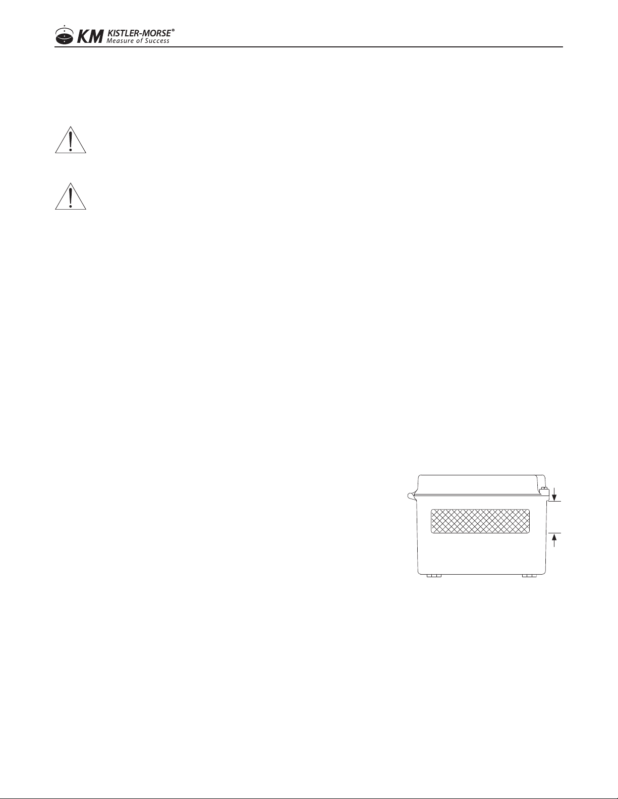
4. Make a hole for the AC cable and the serial and CAT 5 wiring.
Holes should be made in the front 2 inches of the the bottom of the
enclosure (see Figure 1); this allows for appropriate spacing for the
ORB and cables.
5. Clean enclosure of any debris, replace the ORB back into the
enclosure, using all four (4) mounting screws.
6. Determine desired location for mounting the ORB.
TO MOUNT THE ORB
1. Install feet to the ORB enclosure, tightening at the desired angles for mounting location.
2. Hold the enclosure against the wall in the desired location and mark the positions of the mounting holes.
Place the enclosure in a safe location.
3. Drill the mounting holes in the wall.
4. Attachtheenclosuretothewallusinghardwarethatwillsecureitrmlyinplace.
IV. MECHANICAL INSTALLATION
WARNING: TO PREVENT PERSONAL INJURY OR EQUIPMENT DAMAGE ONCE THE ORB HAS
BEEN CONNECTED TO POWER, DISCONNECT POWER BEFORE ADDING OR REMOVING PCBS OR
MOUNTING THE STAND-ALONE ORB AND DEACTIVATE POWER TO THE CONTROLLER.
CAUTION: DO NOT ROUTE SERIAL CABLES IN THE SAME CONDUIT WITH AC POWER CABLES.
ONLY USE SIKAFLEX 1A POLYURETHANE SEALANT OR DOW CORNING RTV 738 OR 739. OTHER
SEALANTS MAY CONTAIN ACETIC ACID WHICH IS HARMFUL TO SENSORS AND ELECTRONICS. DO
NOT DRILL HOLES THROUGH THE TOP AS THIS MAY ALLOW MOISTURE SEEPAGE, WHICH CAN
DAMAGE THE ELECTRONICS AND VOID THE WARRANTY.
Figure 1.
2”
Bottom View
55
97-1167-01 Rev. J
www.kistlermorse.com

V. ELECTRICAL INSTALLATION
WARNING: REMOVE POWER FROM THE UNIT BEFORE INSTALLING, REMOVING, OR MAKING
ADJUSTMENTS
GENERAL SAFETY
When using electrical equipment, you should always follow basic safety precautions, including the following:
• Theinstallation/wiringofthisproductmustcomplywithallnational,federal,state,municipal,andlocal
codes that apply.
• Properlygroundtheenclosuretoanadequateearthground.
• Donotmodifyanyfactorywiring.Connectionsshouldonlybemadetotheterminalsdescribedinthis
section.
• Allconnectionstotheunitmustuseconductorswithaninsulationratingof300Vminimum,ratedfor
105C,aminimumammabilityratingofVW-1,andbeofappropriategaugeforthevoltageandcurrent
required (see specs).
• Donotallowmoisturetoentertheelectronicsenclosure.Conduitshouldslopedownwardfromthe
housing. Install drip loops and seal conduit with silicone rubber product.
DISCONNECT REQUIREMENTS FOR PERMANENTLY INSTALLED EQUIPMENT
A dedicated disconnecting device (circuit breaker) must be provided for the proper installation of the unit. If
independent circuits are used for power input and main relay outputs, individual disconnects are required.
Disconnects must meet the following requirements:
• Locatedincloseproximitytothedevice
• Easilyaccessibletotheoperator
• Appropriatelymarkedasthedisconnectforthedeviceandassociatedcircuit
• Sizedappropriatelytotherequirementsoftheprotectedcircuit(SeeSpecications)
PROTECTIVE EARTH GROUND
To eliminate shock hazards in the unlikely event of an internal insulation breakdown, the unit is provided with a
“protective earth” ( ) lead which must be connected to earth ground ( ). In addition, the input power
ground lead must be connected to the “protective earth” ( ) terminal provided. Wire sizes must be selected
such that it can safely carry the sum total of all circuits’ maximum amperage.
6
697-1167-01 Rev. J
www.kistlermorse.com

WIRING POWER DIAGRAMS
• Allwiringshowniscustomerinstalled.
• RouteallACwiringseparatefromallotherwiring.
• Topreventgroundloops,connectsignalwireshieldsatoneendonly.
• Eachofthethree(3)COMportscanbeconguredindividuallyfortheRS-422orRS-485tosatisfythe
COM requirements of the equipment that the ORB is being connected to. Up to 100 pieces of RS-
422 or RS-485 based equipment can be connected to a single COM port provided that each piece of
equipment is given a unique address.
• ForEthernetapplications,maximumcablelengthis300ft(90m).
• ForRS-232applications,maximumcablelengthis50ft(15m).
• ForRS-422applications,maximumcablelengthis4000ft(1200m).RecommendusingBelden®8723 or
equivalent.
• ForRS-485applications,maximumcablelengthis4000ft(1200m).Recommendusing22AWG2pair
twisted shield Belden 8723 or equivalent.
77
97-1167-01 Rev. J
www.kistlermorse.com

FIGURE 2: Wiring For RS-422 Serial Connections
ORB Board Layout
KM/RS-422 Jumper
Configuration
Port 1 Port 2 Port 3
Service Port
RS-422 Serial Connections
IN
+
SHLD
OUT
-+ -
TB4
SERIAL
DATA
+ -
IN
+-
OUT
TB4
SERIAL
DATA
SHLD
DEVICE #20
(SLAVE)
DEVICE #2
(SLAVE)
DATA
SERIAL
OUT
+
IN
-+
TB4
SHLD
-
DEVICE #1
(SLAVE)
88 97-1167-01 Rev. J
www.kistlermorse.com

FIGURE 3: Wiring For RS-485 Connections (Modbus)
ORB Board Layout
RS-485 Connections
MODBUS/RS-485
Jumper Configuration
Port 1 Port 2 Port 3
Service Port
120 Ώ
120 Ώ
99
97-1167-01 Rev. J
www.kistlermorse.com

VI. SET-UP
TosetuptheORB,rstdetermineifanEthernetorSerialConnectionisbeingused.
FOR ETHERNET CONNECTION
Requires cross-over cable.
1. Go to Control Panel, choose Network Connections.
2. Identify the correct Network Connection, not a wireless connection.
3. Choose Properties of chosen Network Connection.
4. Choose Properties of the TCP/IP Protocol.
5. Write down the current computer IP address.
6. Change the computer IP address to 192.168.1.171 with a sub-address of 255.255.255.0; gateway is left blank
7. Apply changes. Rebooting the computer may be necessary.
8. Connect the cross-over cable from the Ethernet port on the ORB to the Ethernet port in the computer;
watch Network icon for connectivity.
9. Launch a web browser.
10. Type 192.168.1.170 into the address window.
11. Log into the ORB using a web browser.
User Login = Admin
Password = Admin
NOTE: If using Internet Explorer, the time must be changed to the local time.
12. Choose Set Up EtherNet on the main screen
13. Match the ORB IP address to the assigned IP address, assigned by your IT group.
14. Choose Update ORB
15.Conrmationscreenwillappear,reviewandclickOK
16. Disconnect the cross over cable and plug the ORB into your network.
17. Open new Internet browser and type in new IP address.
1010 97-1167-01 Rev. J
www.kistlermorse.com

18. Now the ORB is ready to work on your network.
19. Close the browser to log out of the ORB.
20. Change the computer IP address back to the original - this is the IP address written down in Step 5
(See Steps 1-5 to access the address location again)
CREATE A RECORD TABLE
NOTE: Each device on a serial network must have a unique serial address. Each product can be set differently,
refer to the Installation & Operation manual for individual products. The table below can be used to capture the
required data for each device, add rows as needed.
SILO DESCRIPTION PRODUCT NAME (MODEL) SERIAL ADDRESS (DECIMAL)
Sample: North silo Yo-Yo 000
TO SET UP THE VESSELS IN THE ORB
1. Log in to the ORB normally using a web browser.
User Login = Admin
Password = Admin
2. Scan for devices
a. Go to the NETWORKING tab
b. Click Set Up Serial Ports
c. ChoosethePortthatcorrespondswiththewiringoftheORB,clickCongure
d. Choose the setting that matches the jumper setting (RS-485/MODBUS or KM/RS-422), click Update
e. Choose Manually Add Devices
f. Locate each serial address block (reference record table if required), click SCAN
g. Click continue, repeat until all devices have been successfully added. The ORB is now ready to
begin taking readings.
3. Acompanyadministratorshouldbesetup,aswellas,anyadditionaluserproles.SeeUsingtheORB,
Section VII for detailed instructions.
1111
97-1167-01 Rev. J
www.kistlermorse.com

FOR SERIAL CONNECTION
Requires a DB9 cable (Null modem only – female both ends) and PuTTY.exe for the connection. PuTTY.exe can
be download from the Bindicator website (www.bindicator.com).
1. Plug DB9 cable into ORB service port and your computer COM port.
2. OpenPuttyConguration
3. TypeCOM1intoSerialLineeld.
4. Select the Serial button for Connection Type
5. Click open
6. A blank screen may appear, until ENTER is pressed.
7. Enter USER NAME = kmc, press ENTER
8. Enter PASSWORD = kmc, press ENTER
9. Press1andENTERtocongurethenetwork
10. Press 1 to change the IP address, press ENTER
11. Enter new IP address - provided by your IT group, press ENTER
12. Press 2 to change the Subnet/Netmask, press ENTER
13. Enter new Subnet/Netmask - provided by your IT group, press ENTER
14. Press 3 to change the Gateway, press ENTER
15. Enter new Gateway - provided by your IT group, press ENTER
16. Press ‘S’ to save the settings, press ENTER.
17. Close Putty program.
18. Connect to the ORB to your network.
19. Log in to the ORB using a web browser.
CREATE A RECORD TABLE
NOTE: Each device on a serial network must have a unique serial address. Each product can be set differently,
refer to the Installation & Operation manual for individual products). The table below can be used to capture the
required data for each device, add rows as needed.
SILO DESCRIPTION PRODUCT NAME (MODEL) SERIAL ADDRESS (DECIMAL)
Sample: North silo Yo-Yo 000
1212 97-1167-01 Rev. J
www.kistlermorse.com

TO SET UP THE VESSELS IN THE ORB
1. Log in to the ORB normally using a web browser.
User Login = Admin
Password = Admin
2. Scan for devices
a. Go to the NETWORKING tab
b. Click Set Up Serial Ports
c. ChoosethePortthatcorrespondswiththewiringoftheORB,clickCongure
d. Choose the setting that matches the jumper setting (RS-485/MODBUS or KM/RS-422), click Update
e. Choose Manually Add Devices
f. Locate each serial address block (reference record table if required), click SCAN
g. Click continue, repeat until all devices have been successfully added. The ORB is now ready to
begin taking readings.
3. Acompanyadministratorshouldbesetup,aswellas,anyadditionaluserproles.SeeUsingtheORB,
Section VII for detailed instructions.
VII. USING THE ORB
TO SET COMPANY NAME AND LOGO
Choose ADMINISTRATION TAB/SET COMPANY NAME
1. Enter your company name and location
2. To add your company logo
a. ClickBrowseandndtheleonyourcomputer
b. Click the Use logo box
c. Click Update
3. Your name will now appear in the middle of the title bar, with the location underneath; the logo will be
updated on the left side of the screen. The ORB, iLevel logo will remain
TO UPDATE OR CHANGE THE TIME OF THE ORB
Choose ADMINISTRATION TAB/SET TIME AND DATE
1. User must have Write permission to make changes to this screen
2. Select the region of the units current location
3. Click Submit
TO ADD ADDITIONAL DEVICES
After the ORB has initially been set up, choose NETWORKING TAB/SET UP SERIAL PORTS
1. ChoosethePortthatcorrespondswiththewiringoftheORB,clickCongure
1313
97-1167-01 Rev. J
www.kistlermorse.com

2. Choose the setting that matches the jumper setting (RS-485/MODBUS or KM/RS-422), click Update
3. Choose Manually Add Devices
4. Locate each serial address block (reference record table if required), click SCAN
5. Click continue. Repeat until all devices have been successfully added
TO EDIT THE SETTINGS OF EACH INDIVIDUAL VESSEL
Click the hyperlink above the image (See screen shot)
1. Updatethefollowingelds,asneeded
a. VesselIdentier
b. Vessel contents (Optional)
c. Color, shown on the main home screen of the ORB
d. Vessel shape
e. Maximum Capacity
f. Minimum Capacity
2. Click Update
TO SET A STRAPPING TABLE
Click the hyperlink above the image
1. Choose Edit Strapping Table
2. InsertInputdata;uncorrecteddatafromthedevice,customerspecied
3. InsertOutputdata;correcteddatafromthedevice,customerspecied
4. Click Update
This is an advanced feature of the ORB set up. It is often used when a user wishes to set the tank parameters in
a particular way when determining levels.
TO SET ALARMS ON EACH VESSEL
Choose MANAGEMENT TAB\MANAGE ALARMS
1. Choose Manage Alarms
2. Click on the vessel that needs adjusted
3. Updateeldsasrequired
a. Trigger–dene
b. Management type
c. Deadband
d. Display type
e. Title
f. Message Emailed
g. Email Addresses
1414 97-1167-01 Rev. J
www.kistlermorse.com

4. Click Submit
NOTE: Email alarms require SMTP server set up
TO UPDATE OR ADjUST A VESSEL PARAMETER
Choose MANAGEMENT TAB/MANAGE DEVICES
1. Choose Manage Devices
2. Click on the vessel that needs adjusted
3. Click on parameter to change
4. Update settings as required
5. Click Update
TO UPDATE OR ADD USER IDS TO HAVE ACCESS TO THE ORB OR THE PERMISSIONS FOR EACH
Choose MANAGEMENT TAB/MANAGE PERSONNEL
1. Manage Users to create, edit or delete accounts
a. Fillinalleldstocreateanaccount
b. Select which vessels each user should have access to in the ORB
2. Manage Roles to create, edit or delete permission roles
a. Select appropriate access for each role for the ORB
b. Create a new role
TO MANAGE OR CREATE REPORTS
Choose MANAGEMENT TAB/MANAGE REPORTS
1. To see a report
a. Click on the report name
b. Add email address(es) where the report should be sent
c. Click submit
2. To create a new report
a. Click Add New Report
b. Create Title
c. Add Devices
d. Set the desired schedule
e. Add email address(es) where the report should be sent
f. Click submit
1515
97-1167-01 Rev. J
www.kistlermorse.com

VIII. TROUBLESHOOTING
PROBLEM POSSIBLE CAUSE SOLUTION
Power On LED is off Power Switch Off Turn power On
10/100 Light On 10M bit connection No problem
Network cable not connected Connect Network cable
Device Not Displayed on
Main page Page not setup to display all devices Click edit View and update view, adding devices
An action is greyed out Permission not setup Administrator must manage users and roles to give the permission
required.
No communication to
Devices
Jumpers set incorrectly on ORB PCB Setup jumpers per page 8, 9
Wiring incorrect Correct wiring per page 8, 9
Com port not setup correctly Click setup serial ports and correctly setup the serial port being used
Broken serial cable Do a continuity check or serial cable
Device power off Check power on each device
Damaged ORB serial port Login as an Admin, click setup serial ports and run the loop back
test. See Figure 4 for wiring of loopback
120 ΏEnd of Line Resistor not
installed for Modbus See wiring per page 9
Unable to connect to ORB
Incorrectly set IP address Short pins 2 and 3 of the service DB9 serial port during a power
cycle to set the IP address back to 192.168.1.170
Figure 4. Wiring for Loop Back Tests
RS-485 RS-422
1616 97-1167-01 Rev. J
www.kistlermorse.com
Table of contents