Kitsrus Kit 106 User manual

Kit 106. 50 Watt Audio Amplifier
Page 1 of 5
his kit is based on an amazing IC amplifier
module from ST Electronics, the TDA7294. It
is intended for use as a high quality audio
class AB amplifier in hi-fi applications. It has very
low noise and distortion, wide bandwidth and good
output current capability, enabling it to supply high
power into both 4Ω and 8Ω loads. It has both short
circuit and thermal protection, so is quite robust.
With the addition of a handful of parts and a suitable
power supply, this module will deliver over 50W
RMS into 4 or 8 ohms with < 0.1% Total Harmonic
Distortion (THD) and < 0.1% Intermodulation
Distortion (IMD). A similar circuit was published in
Elektor magazine, 11/96.
It is also suitable as a replacement power amp stage,
or upgrade for many existing amplifiers of between
30W-50W, provided they have a suitable dual
supply, and most do.
Specifications (± 35V D.C. power supply)
Output power : > 50W RMS, 4-8 Ω load
~ 80W into 4Ω max.
~ 60W into 8Ωmax.
Gain 24 dB (30dB modification)
Input sensitivity : 1.3V for 50W, 8 ohm
0.9V for 50W, 4 ohm
(0.6V, 50W, 8Ω, G=30dB)
Input impedance : 10kΩ
Signal-to-Noise ratio : > 95 dB, (>105 dBA)
Frequency response : ~ 20Hz - 200kHz, –3 dB
Slew rate : > 10V/uS
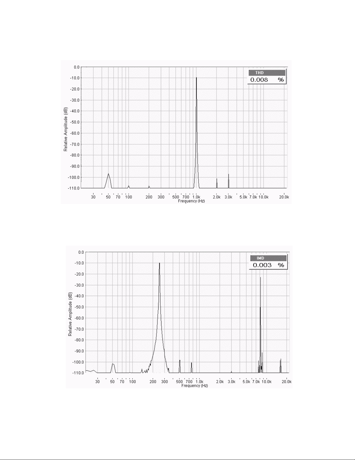
THD : < 0.01%, 1W-40W,1kHz
< 0.1%, at 50W, 20-20kHz
IMD : < 0.01%, 1W
Construction :
* Please note C6 on the PCB overlay is shown the
wrong way around. The positive should go to pin 6
of the IC, as shown on the circuit diagram.
Start with the lowest height components first,
resistors and capacitors. Keep one of the longer lead
off cuts to use as the link. Be careful to get the
electrolytic capacitors in the correct way around. The
positive lead is marked on the overlay. The negative
lead is marked on the body of each capacitor. Leave
the IC and the big electrolytic capacitors to last.
Make sure that the IC is at right-angles to the PCB
and the heatsink chosen will fit, before soldering.
Important : You must supply a heavy duty heatsink
rated at least 1.4 oC/W or better. This is not supplied
with the kit, it must be obtained separately then
drilled to suit. If building two kits for a stereo amp,
you may prefer to use one larger heatsink, and mount
a board at either end. This is often cheaper than two
smaller ones. A silicon impregnated insulating
washer and insulation bush are provided in the kit.
How it Works :
Most of the circuitry is contained within the IC
module. The input signal is applied to pin 3 via
capacitor C1 and low-pass filter R1/C2. The filter
improves the pulse response and helps stop RF
signals. The lower -3dB point is determined by
R2/C1 and R4/C3. This is approximately 20Hz for
the values used. The upper -3dB point is over
200kHz. C7/C8 and C9/C10 provide extra power
supply filtering or decoupling.
R3/R4 are the feedback resistors. The gain is
1+R3/R4 which is approx 16 times, or 24dB. If you
wish to increase the input sensitivity you may
change the resistors to suit. Changing R3 to 22k
would increase the gain to 30dB and lower the input
required for 50W into 8Ω, to 0.6V, without affecting
performance too much. If you reduce the value of R4
you will also need to increase C3 to maintain bass
response, as this sets the feedback low frequency roll
off.
Pin 10 is a mute input and pin 9 provides a standby
mode. Muting should always take place before
standby mode is selected. Connecting these pins
permanently to the supply rail (insert links provided)
ensures that the amplifier comes on immediately on
power up. Any switch-on clicks may be eliminated
by increasing the time constants of R5/C4 and R6/C5
if necessary. See the ST data sheet for more details.
Power Supply :
The maximum supply voltage of the IC is ±40V.
However the maximum dissipation of the IC can be
exceeded even at a lower voltage. Therefore the
supply voltage used need not be more than ±35V.
This can be constructed using a 50V center tapped
transformer, a diode bridge rated at 5A (min.) and a
pair of electrolytic capacitors, as shown below.
A lower secondary voltage transformer could also be
used but the reduced DC voltage will result in less
power output into 8 ohms. You can still obtain 50W
into 4 ohms with only 24V supply rails. A 36V C.T.
transformer will give you approx ±25V rails. The
mains transformer used should be rated at a
minimum of 80VA. If you want to run two modules
in a stereo amplifier you can use a common power
supply. In this case the transformer should be rated
at 150VA or greater.
T

Kit 106. 50 Watt Audio Amplifier
Page 2 of 5
Testing :
Before applying power, check that all parts are
inserted in the correct locations. Make sure that the
electrolytic capacitors are the right way round.
Check the power supply voltages before connecting
the power supply to the amplifier. Then connect the
power supply leads with a current meter (or
multimeter set to read amps) in series with the
positive rail. Connect a load resistor to the speaker
output, and short out the input terminals. Make sure
there are links inserted for Mute and Standby.
Switch on the power and check that the current
settles down to between 20 and 60mA. There will be
a brief surge as the filter capacitors charge. Also
check the DC voltage at the output is not more than
200mV before connecting a speaker.
Note : Do not operate the module without a
heatsink. You must have the heatsink fitted,
otherwise the thermal overload protection circuit will
cut in and switch the device off. The heatsink tab on
the TDA7294 IC is internally connected to the
negative supply rail. Therefore If the heatsink is
connected to an earthed metal enclosure, the IC
must be insulated from the heatsink. If not, the
negative supply rail will be shorted to ground. A
silicon impregnated rubber washer and a plastic
insulating bush are provided for this purpose.
To minimize noise and distortion, keep the input
signal leads away from the power supply and output
leads. Use screened cable for input leads, and
suitably large cables for all DC power wires and
speaker connections. Remember the current may be
a few amps in each case. Make sure all earths
connect at a single point to eliminate hum caused by
ground loops.
Operation :
No input attenuation is provided, so if you are not
using a separate pre-amp then you may require a
volume control. This can be a 10k ohm logarithmic
potentiometer connected as shown. If you are using
two modules for stereo, then a dual gang pot will be
required. A CD player can be connected like this and
will drive the module to full power without a pre-
amp. Alternatively you might like to use one of our
stereo pre-amp or tone control kits.
The maximum continuous power you can obtain will
depend largely on the size of the power supply and
the size of the heatsink used. make sure both are
sufficiently large for the intended application. The
IC has internal thermal protection that causes the
mute to cut in at 145°C and switches the amplifier
into standby at 150°C. You should however avoid
operating at such high temperatures by using a
suitably large heatsink for the average power you
need. A heatsink fan is an alternative to a larger
heatsink, if fan noise is not a problem.
If it does not work :
Dry joints caused by poor soldering are the most
common reason that the circuit does not work. Check
all soldered joints carefully under a good light. Re-
solder any that look suspicious. Check that all
components are in their correct position on the PCB,
and the electrolytic capacitors in the right way round.
Make sure you have inserted the links for Mute and
Standby. Remember that the metal tab on the IC is
internally connected to the negative supply rail, so
check that the negative supply rail is not shorted to
ground.
The data sheet on the TDA7294 IC is available from
the ST Electronics web site at :
http://www.st.com
or our web site at :
http://www.kitsrus.com
Parts List :
Resistors (1/4 W carbon)
150R (brown green brown) R1 1
10K (brown black orange) R2, R3, R5 3
680R (blue grey brown) R4 1
22K (red red orange) R6 1
Capacitors
1u5F or 1u MKT polyester C1 1
2n7F MKT polyester C2 1
22uF 63V electrolytic C3, C6 2
10uF 63V electrolytic C4, C5 2
2200uF 50V electrolytic C7, C9 2
100nF MKT polyester C8, C10 2
Semiconductors
TDA 7294 IC1 1
Miscellaneous
K106 PCB 1
Header, 2 pin 2
Jumper 2
Silicon impregnated insulating washer 1
Insulating bush 1
Screw, 3 x 12mm 1
N
ut, 3m
m
1
Washer, 3mm 1

Kit 106. 50 Watt Audio Amplifier
Page 3 of 5
Circuit Diagram
* Please note C6 is shown incorrectly on the
PCB overlay. The circuit diagram is correct.
Suggested Power supply circuit
+
Input
13
Speaker
(not included)
+
_
+
+
+
++
C1
1u5
Negative
24 - 36V
DC
IC1
TDA 7294
2200uF
25V
C9
2200 uF
25V
C8
100nF
C10
100nF
C7
+
Gnd 22uF
63V
C6
10k log Pot
Input
Attenuator
(Not Included)
.
7
R1
150R
R2
10k
C2
2n7
1815
R3
10k
R4
680R
3
4
14
6
Positive
24 - 36V
DC
C3
22uF
63V
2
DC
Gnd
R5
10k
R6
22k
Mute
Standby
10
9
C4
10uF
63V
C5
10 uF
63V
Output
(optional)
.
For a stereo pair you may double the VA of the transformer, diode bridge current,
increase capacitance and fuse rating.
Alternatively use two complete supplies.
A
N
E
Fuse
Switch 1a
Switch 1b
4* Diodes 5A/200V
or Diode Bridge
Mains
I/P
4700uF
50V
4700uF
50V
++
_
+Gnd
35V
35V
Transformer
50V 80VA
centre tapped
.
.
2-3A
* All
g
rounds must connect at the same poin
t
(+/- 25V AC)

Kit 106. 50 Watt Audio Amplifier
Page 4 of 5
Harmonic Distortion at 50W RMS
4ohms, 1 kHz input
Photo of completed Kit (heatsink
must be purchased separately.)

Kit 106. 50 Watt Audio Amplifier
Page 5 of 5
Harmonic Distortion at 1W, 1 kHz
Intermodulation Distortion at 1W
250 Hz, 8020 Hz, 4:1
Table of contents