Klaro 970716 User manual

GERMAN
DESIGN AND
ENGINEERING
KLAROconnect
Operating manual
317-EN-0622
Direct access
to the plant data
Operational safety
for the wastewater
treatment plant
4G
LAN
We provide clear water

Operating Instructions KLAROconnect
Status 06/2022 KLARO GmbH Page 2/21
Original operating instructions
Communication module KLAROcon-
nect

Operating Instructions KLAROconnect
Status 06/2022 KLARO GmbH Page 2/21
Original operating instructions
Communication module KLAROcon-
nect
Operating Instructions KLAROconnect
Status 06/2022 KLARO GmbH Page 3/21
Content
ABOUT THESE OPERATING INSTRUCTIONS............................................................................. 41
1.1 ORIGINAL LANGUAGE OF THE DOCUMENTARY ................................................................................ 4
1.2 COPYRIGHT................................................................................................................................. 4
1.3 COMPLETENESS .......................................................................................................................... 4
1.4 RESPONSIBILITY .......................................................................................................................... 4
ABBREVIATIONS............................................................................................................................ 52
PRODUCT DESCRIPTION .............................................................................................................. 53
3.1 SYSTEM DESCRIPTION ................................................................................................................. 5
3.2 SCOPE OF DELIVERY.................................................................................................................... 6
3.3 MOUNTING KLAROCONNECT....................................................................................................... 7
3.3.1 Velcro fastening ................................................................................................................. 7
3.3.2 Mounting adapter (available from WAGO) ........................................................................ 7
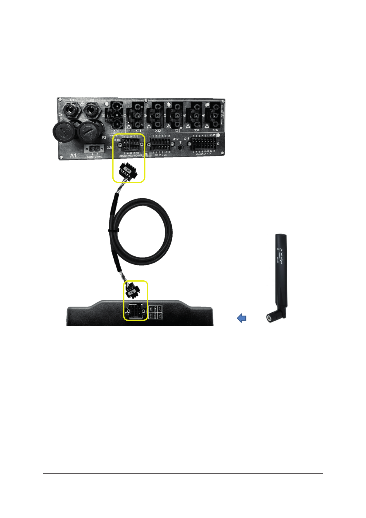
BASIC CONNECTION DIAGRAM .......................................................................................................... 8
COMMISSIONING ........................................................................................................................... 94
4.1 ANTENNA .................................................................................................................................... 9
4.2 MINI SIM CARD ........................................................................................................................... 9
4.3 SWITCH ON KLAROCONNECT ...................................................................................................... 9
4.4 CONTROL CONFIGURATION........................................................................................................... 9
4.5 CREATE ATTACHMENT IN WEBMONITOR ....................................................................................... 9
INTERFACE DESCRIPTION ......................................................................................................... 105
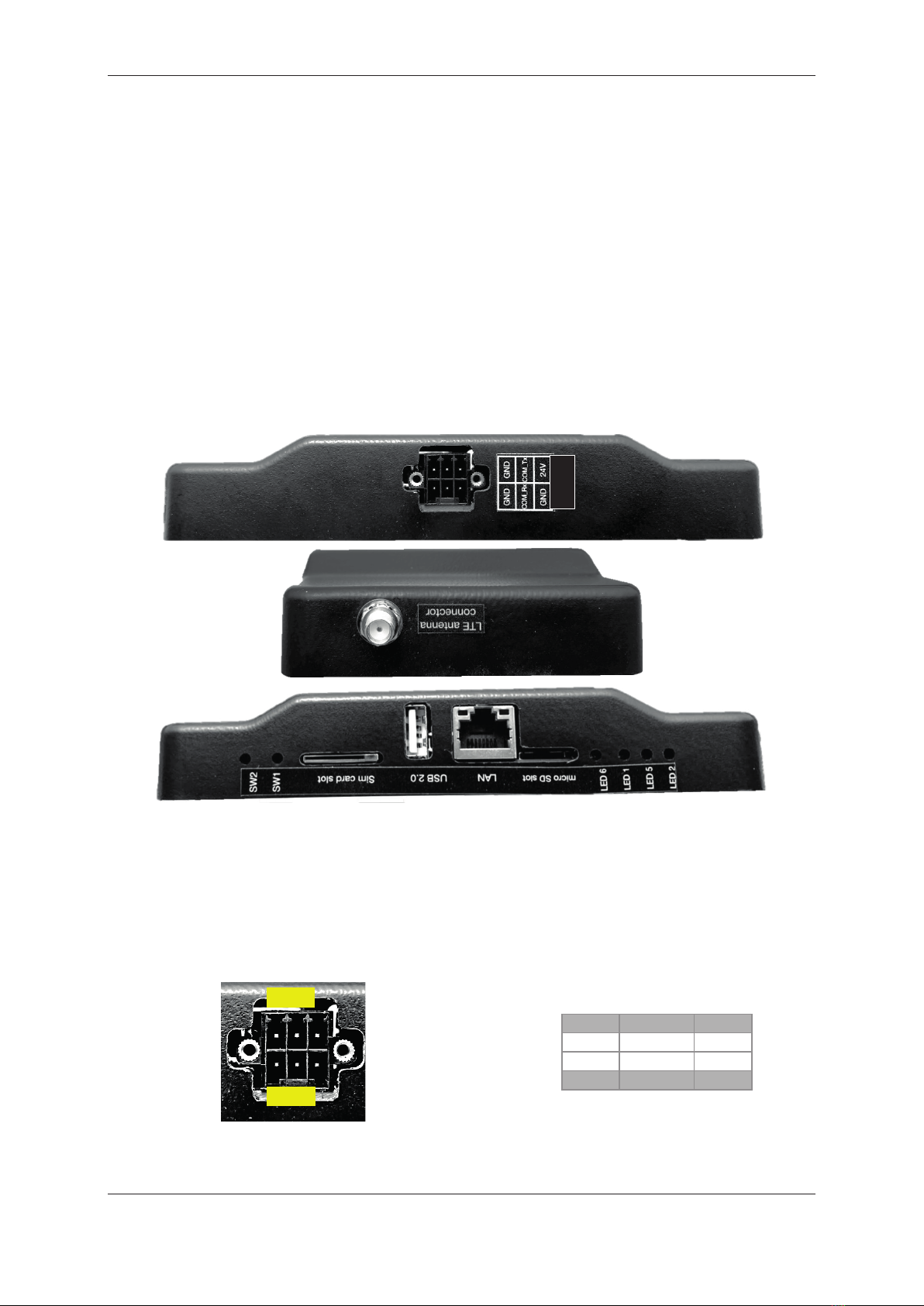
5.1 ELECTRICAL INTERFACES ........................................................................................................... 10
5.1.1 Power supply and serial interface (-X6)........................................................................... 10
5.1.2 USB 2.0............................................................................................................................ 11
5.1.3 LAN Ethernet connection................................................................................................. 11
5.1.4 SMA antenna connection................................................................................................. 11
5.2 OPERATING ELEMENTS .............................................................................................................. 12
5.2.1 SW1 - Reset button ......................................................................................................... 12
5.2.2 SW2 - Reset button ......................................................................................................... 12
5.3 CARD SLOTS ............................................................................................................................. 12
5.3.1 Mini-SIM- card slot ........................................................................................................... 12
5.3.2 Micro SD card slot ........................................................................................................... 13
5.4 OPTICAL DISPLAYS .................................................................................................................... 13
5.4.1 LED6 ................................................................................................................................ 13
5.4.2 LED5 ................................................................................................................................ 13
CONNECTING THE KLAROCONNECT TO A COMPUTER........................................................ 146
6.1 KLAROCONNECT CONFIGURATION ............................................................................................ 14
6.2 SIM PROFILE CONFIGURATION.................................................................................................... 14
6.2.1 Instructions SIM profile configuration .............................................................................. 14
6.3WEBSOCKET URI ...................................................................................................................... 17
6.3.1 Websocket URI Configuration Guide............................................................................... 17
SOFTWARE UPDATE VIA MICRO SD CARD ............................................................................. 187
APPENDIX ..................................................................................................................................... 198
8.1 DIMENSIONS KLAROCONNECT .................................................................................................. 19
8.2 TECHNICAL DATA KLAROCONNECT............................................................................................ 19
8.3 LTE INDOOR ANTENNA............................................................................................................... 21
8.4 LTE OUTDOOR ANTENNA ........................................................................................................... 21
8.5 NAMEPLATE .............................................................................................................................. 22

Operating Instructions KLAROconnect
Status 06/2022 KLARO GmbH Page 4/21
IMPORTANT:
•These operating instructions contain information on the installation of electrical com-
ponents and must therefore be read before mounting and commissioning the set!
•All safety instructions must be observed!
•Keep for future use.
About these operating instructions1
These operating instructions are part of the product and must be read before the unit is put into
operation. The operating instructions must be kept for the entire service life of the system and must
be available for reference.
1.1 Original language of the documentary
This documentation was originally written in German.
1.2 Copyright
© KLARO GmbH
Spitzwegstrasse 63
D-95447 Bayreuth
Phone: 0049-921-16279120
E-mail: info@klaro.eu
Internet: www.klaro.eu
All rights expressly reserved. Reproduction or communication to third parties, in whatever form, is not
permitted without the written consent of KLARO GmbH.
1.3 Completeness
These instructions have been prepared with due care. Any liability of the manufacturer due to incorrect
or missing information as well as linguistic deficiencies or typographical errors in the documentation is
excluded. Should you find any incompleteness and/or errors, please inform us at the above address.
In preparing these instructions, care was taken to ensure that the facts stated therein correspond as
closely as possible to the associated system. Nevertheless, all technical data, dimensions and illustra-
tions in these instructions are non-binding. Possible claims regarding the specific design of a system
cannot be derived from them.
We reserve the right to make changes to a system within the scope of improvements and further de-
velopments without changing these instructions. An obligation to install modified technology in already
completed and delivered systems cannot be derived from this.
This documentation is updated regularly.
1.4 Responsibility
Any responsibility of the manufacturer does not apply:
•non-observance or insufficient use of the information in this manual,
•Use of spare parts or parts on the system that have not been approved by KLARO GmbH,
•Removal, manipulation or bypassing of protective devices,
•unauthorised changes to the system,
•improper execution of maintenance and replacement of spare parts.
Unauthorised modifications to the system or operation of the system outside the specifications provid-
ed by the manufacturer will invalidate any warranty claims.
Operating Instructions KLAROconnect
Status 06/2022 KLARO GmbH Page 5/21
Abbreviations2
SIM
Subscriber Identity Module
PLC (English PLC)
Programmable Logic Controller (PLC)
RS232
Recommended Standard 232
ISM
Industrial, Scientific and Medical
URI
Uniform Resource Identifier
SCADA
Supervisory control and data acquisition
HTTP
Hypertext Transfer Protocol
JSON
Java Script Object Notation
WI
Web interface
GUI
Graphical User Interface
APN
Access Point Name
M2M
Machine to Machine
IoT
Internet of Things
MAC
Media Access Control
QR
Quick Response
Product description3
3.1 System description
KLAROconnect is used for communication between the wastewater treatment plant and the KLARO
WebMonitor. KLARO WebMonitor offers the possibility of remote monitoring, remote maintenance
and remote control of the wastewater treatment plant from a distance using a smartphone or computer
via the internet. You can find more information about this at https://klaro-webmonitor.de/ . Via KLARO-
connect, all operation-relevant data such as settings, events and operating hour meter readings of the
KLAROcontrol.S and KLAROcontrol. M are transmitted to the KLARO WebMonitor.
KLAROconnect combines a 4G module and a LAN adapter. The enclosed antenna covers the fre-
quency ranges 790 - 960 MHz, 1710 - 2170 MHz, 2570 - 2620 MHz. You will find more detailed infor-
mation in the appendix to these operating instructions.
KLAROconnect is specifically optimised for M2M and IoT applications, delivering maximum data rates
of up to 10 Mbps downlink and 5 Mbps uplink. KLAROconnect (SIM) is backward compatible with ex-
isting EDGE and GSM/GPRS networks, ensuring that it can connect in remote areas without 4G or 3G
coverage.
The power connection is made directly to the control unit via the data cable included in the scope of
delivery (art. no.: 982223). In the event of a power failure, KLAROconnect no longer works. Data
transmission between KLAROconnect and the control is also carried out via the data cable.
The status of KLAROconnect is displayed via control LEDs.
A Velcro strap is supplied as standard for attachment.

Operating Instructions KLAROconnect
Status 06/2022 KLARO GmbH Page 6/21
3.2 Scope of delivery
970716Additional package KLAROconnect indoor antenna I-cabinet PP, A-cabinet PP
970717Additional package KLAROconnect indoor antennaI-cabinet1/2/3, A-cabinet4/5, M-technology
970718Additional package KLAROconnect indoor antenna A-Uni. / -pillar
970719Additional package KLAROconnect external aerialA-cabinet3/4/5/uni / column
Article
Quantity
Designation
970716
970717
970718
970719
901471
1 STK
KLAROconnect
●
●
●
●
982223
1 STK
Data cable
●
●
●
●
901474
1 STK
LTE indoor antenna
●
●
●
●
901476
1 STK
LTE outdoor antenna
○
○
○
●
980194
10 CM
Velcro tape
●
●
●
●
901475
1 STK
Ethernet extension cable
●
○
○
○
980314
1 STK
Cable gland M16
○
●
○
●
980311
1 STK
Locknut M16
○
●
○
●
● Included in the scope of delivery
○ not included in the scope of delivery
The following is a pictorial representation of components from the KLARO WebMonitor® packages
(Velcro tape, cable gland and locknut are not shown).
Illustration 1901474 LTE indoor antenna with tilt joint (always
included as standard)
Picture 2901476 LTE outdoor antenna SMA 4G
Illustration 3901475 Ethernet extension cable FTP Cat6 right-
angled 0.5m (as standard for I-cabinet PP)
Illustration 4982223 Data cable KLAROconnect
KLAROcontrol.S/M
Operating Instructions KLAROconnect
Status 06/2022 KLARO GmbH Page 7/21
3.3 Mounting KLAROconnect
3.3.1 Velcro fastening
The Velcro tape included with the KLAROconnect is used
to mount the communication module.
Note: The glued areas must be made dust-free before
applying the Velcro tape.
3.3.2 Mounting adapter (available from WAGO)
The KLAROconnect can be mounted on a DIN 35 rail using two mounting feet (WAGO 209-123). To
do this, the mounting feet are mounted with the screws on the underside in the holes provided.

Operating Instructions KLAROconnect
Status 06/2022 KLARO GmbH Page 8/21
Basic connection diagram
(1) Control unit KLAROcontrol.M or KLAROcontrol.S
(2) KLAROconnect (communication module)
(3) Antenna
(4) Data cable (serial cable + power supply)
(1)
(4)
(3)
(2)

Operating Instructions KLAROconnect
Status 06/2022 KLARO GmbH Page 8/21
Basic connection diagram
(1) Control unit KLAROcontrol.M or KLAROcontrol.S
(2) KLAROconnect (communication module)
(3) Antenna
(4) Data cable (serial cable + power supply)
(1)
(4)
(3)
(2)
Operating Instructions KLAROconnect
Status 06/2022 KLARO GmbH Page 9/21
Commissioning4
In the LAN adapter operating mode, the chapters 4.1 and 4.2 can be skipped.
4.1 Antenna
The antenna must be connected to the antenna socket of the KLAROconnect by means of a screw
connection. The antenna must be positioned in such a way that reliable reception is possible. You can
check the reception quality on site by trying out the SIM card in a mobile phone or smartphone before-
hand.
4.2 Mini SIM card
For operation as a 4G module (modem), a valid mini SIM card must be present in the KLAROconnect:
•Mini SIM card format
•Recommended data volume per month >500MB
•The SIM card must be able to transmit M2M
•Deactivate the PIN (to do this, -insert the SIM card -into a mobile phone and deactivate the
PIN request under the menu item "Security").
When the KLAROconnect is switched off (the LEDs are off), insert the SIM card into the device (see
also chapter 5.3.1).
4.3 Switch on KLAROconnect
After the card has been inserted, KLAROconnect can be connected to the power supply (switch on
KLAROcontrol).
The connection with KLAROcontrol is fully automatic. A WEB symbol appears in the KLAROcontrol
display . KLAROconnect needs up to 8 minutes to start up completely.
After successful authentication, LED6 flashes with interval 100ms on, 100ms off, 100ms on, 700ms
off. If a SIM card is used, LED5 flashes with an interval of 1800ms on, 200ms off. The KLAROconnect
is now ready for communication.
If there is no signal changeover, this can have several causes:
Operating mode LAN connection
1. No internet
2. Firewall upstream
3. Missing or incorrect configuration of the KLAROconnect
4. Faulty contacting of the plug connections
Operating mode SIM connection
1. SIM card is not released
2. No mobile phone reception
3. Missing or incorrect configuration of the KLAROconnect
4. Faulty contacting of the plug connections
4.4 Control configuration
No settings need to be made in the control unit.
4.5 Create attachment in WebMonitor
After a successful connection has been established, the system can be created in the WebMonitor.
https://klaro-webmonitor.de

Operating Instructions KLAROconnect
Status 06/2022 KLARO GmbH Page 10/21
Interface description5
The KLAROconnect has the following connections, operating elements and displays:
•X6 connector 6-pin (male) for power supply and RS232
•SMA antenna connector (female) for LTE antenna
•SW2 - Button (without function)
•SW1 - button
•Mini SIM card slot
•USB 2.0 (without function)
•LAN Ethernet connection RJ45
•Micro SD card slot
•LED6 Display
•LED1 Display (without function)
•LED5 Display
•LED2 Display (without function)
Figure 5: Interface overview
5.1 Electrical interfaces
5.1.1 Power supply and serial interface (-X6)
The power connection is made via the data cable included in the scope of delivery (art. no.: 982223).
Data transmission between KLAROconnect and the KLAROcontrol.S or KLAROcotrol. M control unit is
made via the X6 connection.
Pin #1
Pin #3
Pin #5
GND
COM_Tx
24V
GND
COM_Rx
GND
Pin #2
Pin #4
Pin #6
Figure 6Power connection and serial interface -X6, assignment 6-pin WAGO 713-1423/107-000
1 3 5
2 4 6
-X6
Operating Instructions KLAROconnect
Status 06/2022 KLARO GmbH Page 11/21
5.1.2 USB 2.0
Connection: USB 2.0 Type A
Has no function.
5.1.3 LAN Ethernet connection
Connection: RJ45
Both control LEDs serve as a practical means of determining the operating mode of the LAN trans-
ceiver.
The LED1 (right) indicates the status of the transmission. If this LED1 flashes or flickers, then data is
being transmitted.
LED2 (left) lights up when there is a connection to a network.
LED1 is the right-hand LED, LED2 the left-hand LED in the picture.
Figure 7LAN connection
5.1.4 SMA antenna connection
Connection: SMA
The antenna should be screwed on hand-tight without tools. Please only use the LTE antenna includ-
ed in the scope of delivery, other antennas may only be used after consultation with KLARO.
Figure 8: Attach the LTE antenna
LED2
LED1

Operating Instructions KLAROconnect
Status 06/2022 KLARO GmbH Page 12/21
5.2 Operating elements
5.2.1 SW1 - Reset button
SW1 is a reset button. It can be used to restart KLAROconnect. The button can be pressed with a fine
tool or a biro refill.
Illustration 9Press SW1
5.2.2 SW2 - Reset button
Without function.
5.3 Card slots
5.3.1 Mini-SIM- card slot
The SIM card slot is intended for mini-SIM.
Figure 10Insert the mini SIM card into the KLAROconnect.
Removing and inserting the SIM card during operation requires initialisation of the KLAROconnect
software. Therefore, the KLAROconnect must be restarted after reinserting the SIM card. To do this, it
is only necessary to de-energise KLAROconnect for approx. 5 seconds.
No liability is accepted for the loss of data due to the removal of the SIM card dur-
ing operation. No liability is assumed for the correct initialisation of the KLARO-
connect after reinserting a SIM card that was removed during operation.
Operating Instructions KLAROconnect
Status 06/2022 KLARO GmbH Page 13/21
5.3.2 Micro SD card slot
The micro SD card slot is for micro SD.
Figure 11Inserting a micro SD card into KLAROconnect
5.4 Optical displays
5.4.1 LED6
LED 6 indicates the function of the communication module. There are the switching states ON and
OFF. In the ON state, LED6 lights up green.
- Interval 100ms on, 100ms on, 800ms off: normal function
- In the event of a reset or similar, the LED lights up continuously for a few seconds or is continuously
off.
5.4.2 LED5
LED 5 indicates the mobile radio connection of the communication module. There are the switching
states ON and OFF. In the ON state, LED5 lights up green.
- Interval 200ms on, 1800ms off: no connection
- Interval 1800ms on, 200ms off: Connection present

Operating Instructions KLAROconnect
Status 06/2022 KLARO GmbH Page 14/21
Connecting the KLAROconnect to a computer6
To connect the KLAROconnect to a computer, a router and an Ethernet cable are required.
1. Connect KLAROconnect (X6) and KLAROcontrol (X10) with a data cable (art.no.: 982223).
2. Connect KLAROconnect and computer to the router (LAN interface) using an Ethernet cable
(RJ45).
3. Insert the SIM card into KLAROconnect. Unlock the PIN of the SIM card beforehand, e.g. by
mobile phone or smartphone.
4. Establish power supply.
6.1 KLAROconnect Configuration
Entering http://klaro.local in the address bar of the Internet browser calls up the KLAROconnect menu.
KLAROconnect menu can also be called up alternatively via the assigned IP in the DHCP server of
the router.
6.2 SIM profile configuration
•A SIM card profile with details of the APN of the provider can be created via the graphical user
interface (GUI).
•If the profile does not appear in the list after the new creation, reload the page with the F5 key.
•A profile can be connected, disconnected and deleted.
•With the autoconnect option, the created profile is automatically used to establish the connec-
tion when starting.
•The fastest available mobile radio standard is automatically used.
The APN depends on the provider of the SIM card and the purpose of use. APN is required for Ma-
chine to Machine (M2M) use.
Example:
Olivia
Telecom
6.2.1 Instructions SIM profile configuration
1. Call up the KLAROconnect menu via the graphical user interface.
2. Select the menu item "Network-Connections(SIM)
Operating Instructions KLAROconnect
Status 06/2022 KLARO GmbH Page 15/21
3. Delete old SIM profiles. To do this, select "Connection profiles" (tick) and delete with the "Delete"
button. To update the display on the screen, press the F5 key. Then create a new profile with the
"Add" button.
4. A new window "Mobile broadband" opens. The connection name can be freely assigned. The
fields "Connection name" and "APN" must be filled in and are therefore marked with *. The entries
for the User, Password and APN fields are specified by the provider of the SIM card.
5. Describe the fields accordingly and activate "autoconnect".

Operating Instructions KLAROconnect
Status 06/2022 KLARO GmbH Page 16/21
6. Press the "Add" button to save the settings. If the settings are successfully saved, a text with a
green background appears. If the text appears with a red background, the attempt was not suc-
cessful and the procedure must be repeated as described in the instructions. Then close the win-
dow with the Close or X button.
7. If no further configuration is required, the internet browser can be closed. Logging off is not neces-
sary. In the further course, disconnect KLAROconnect and KLAROcontrol from the power supply.
In the next step, carry out the commissioning (chapter 4).
Operating Instructions KLAROconnect
Status 06/2022 KLARO GmbH Page 17/21
6.3 Websocket URI
•Websocket client URI to connect to the WebMonitor can be set via the graphical user inter-
face:
Server Germany: ws://188.174.236.242:4000
Server France: ws://193.248.238.194:4000
Server Australia: ws://119.225.139.2:4000
•Websocket URI can be changed via the graphical user interface and is directly active.
•KLAROconnect forwards the defined messages (JSON) from the WebMonitor server to the
KLAROcontrol (if the connection is established).
•Responses from the KLAROcontrol are passed on to the WebMonitor via the KLAROconnect
using the websocket (ws://).
6.3.1 Websocket URI Configuration Guide
1. Call up the KLAROconnect menu via the graphical user interface.
2. Select the menu item "WebMonitor
3. Enter the URI, e.g. for the use of the KLARO WebMonitor Germany
ws://188.174.236.242:4000, into the websocket field and save it with the "Save" button.
4. Confirm the following message with OK.
5. If no further configuration is required, the internet browser can be closed. Logging off is not
necessary. In the further course, disconnect KLAROconnect and KLAROcontrol from the
power supply. In the next step, carry out the commissioning (chapter 4).

Operating Instructions KLAROconnect
Status 06/2022 KLARO GmbH Page 18/21
Software update via micro SD card7
The software update for KLAROconnect can be made using a micro SD card with an image.
1. Flash the KLAROconnect image onto a micro SD card of at least 4GB using balenaEtcher.
2. Disconnect KLAROconnect and KLAROcontrol from the power supply.
3. Insert the micro SD card into KLAROconnect (see chapter 5.3.1).
4. Connect KLAROconnect to the KLAROcontrol and to the power supply.
5. Firmware is automatically installed from the micro SD card. (The process takes approx. 7 to
10 minutes).
6. After the process is completed, KLAROconnect switches off automatically. (Green power LED
goes off).
7. Disconnect KLAROconnect and the KLAROcontrol from the power supply.
8. Remove the micro SD card.
9. Connect KLAROconnect to the KLAROcontrol and to the power supply.
10. KLAROconnect starts (web interface accessible via LAN on http://klaro.local).
11. Check SIM card configuration and re-create if necessary (chapter 7.3).
12. The arrows in the web symbol in the KLAROcontrol flash at intervals of approx. 10 se-
conds after the connection is established.
Operating Instructions KLAROconnect
Status 06/2022 KLARO GmbH Page 19/21
Appendix8
8.1 Dimensions KLAROconnect
8.2 Technical data KLAROconnect
•4G Module Quectel EG21-G Mini PCIe
•Input voltage range: 24 V
•Operating temperature: -30°C to +85°C
•Dimensions: approx. 158 x 85 x 28 mm
•Weight: 170 g
•Interfaces: Power supply, SIM card reader, microSD, USB, SMA antenna connector (male),
RS232 (V.24/V.28 on SUB-D)
Frequency Bands
EG21-G Mini PCIe:
LTE-FDD: B1/B2/B3/B4/B5/B7/B8/B12/B13/B18/
B19/B20/B25/B26/B28
LTE-TDD: B38/B39/B40/B41
WCDMA: B1/B2/B4/B5/B6/B8/B19
GSM: B2/B3/B5/B8
Voice
Speech Codec Modes:
HR/FR/EFR/AMR/AMR-WB
Echo Arithmeti c:
Echo Cancellati on/Noise Suppression
Audio:
Digital Audio and VoLTE (Voice over LTE) (Opti
onal)
Data
LTE:
LTE-FDD: Max. 10 Mbps (DL)/Max. 5 Mbps (UL)
LTE-TDD: Max. 8.96 Mbps (DL)/
Max. 3.1 Mbps (UL)
UMTS:
HSDPA: Max. 42 Mbps (DL)
HSUPA: Max. 5.76 Mbps (UL)
WCDMA: Max. 384 kbps (DL)/Max. 384 kbps (UL)
GSM:
EDGE: Max. 296 kbps (DL)/Max. 236.8 kbps (UL)
GPRS: Max. 107 kbps (DL)/Max. 85.6 kbps (UL)
Electrical Characteristics
Output Power:
Class 3 (23 dBm ±2 dB) for LTE-FDD bands
Class 3 (23 dBm ±2 dB) for LTE-TDD bands
Class 3 (24 dBm +1/-3 dB) for WCDMA bands
Approvals
Carrier:
Deutsche Telekom (Europe)
Verizon*/AT&T*/T-Mobile*/Sprint* /
U.S. Cellular* (America)

Operating Instructions KLAROconnect
Status 06/2022 KLARO GmbH Page 20/21
Class E2 (27 dBm ±3 dB) for GSM850 8-PSK
Class E2 (27 dBm ±3 dB) for EGSM900 8-PSK
Class E2 (26 dBm ±3 dB) for DCS1800 8-PSK
Class E2 (26 dBm ±3 dB) for PCS1900 8-PSK
Class 4 (33 dBm ±2 dB) for GSM850
Class 4 (33 dBm ±2 dB) for EGSM900
Class 1 (30 dBm ±2 dB) for DCS1800
Class 1 (30 dBm ±2 dB) for PCS1900
Consumpti on:
2.8 mA @Sleep, Typ.
35 mA @Idle
Sensiti vity:
LTE B1: -99.5 dBm (10 MHz)
LTE B2: -99.9 dBm (10 MHz)
LTE B3: -99.7 dBm (10 MHz)
LTE B4: -99.7 dBm (10 MHz)
LTE B5: -99.9 dBm (10 MHz)
LTE B7: -99.2 dBm (10 MHz)
LTE B8: -99.8 dBm (10 MHz)
LTE B12: -99.8 dBm (10 MHz)
LTE B13: -99.5 dBm (10 MHz)
LTE B18: -100 dBm (10 MHz)
LTE B19: -99.9 dBm (10 MHz)
LTE B20: -99.8 dBm (10 MHz)
LTE B25: -100 dBm (10 MHz)
LTE B26: -99.5 dBm (10 MHz)
LTE B28: -99.6 dBm (10 MHz)
LTE B38: -98 dBm (10 MHz)
LTE B39: -99.5 dBm (10 MHz)
LTE B40: -99.2 dBm (10 MHz)
LTE B41: -97.5 dBm (10 MHz)
WCDMA B1: -109.2 dBm
WCDMA B2: -110 dBm
WCDMA B4: -109.7 dBm
WCDMA B5: -110.4 dBm
WCDMA B6: -110.5 dBm
WCDMA B8: -110.5 dBm
WCDMA B19: -110.1 dBm
GSM850: -108 dBm
EGSM900: -108 dBm
DCS1800: -107.5 dBm
PCS1900: -107.5 dBm
Telus* (Canada)
Regulatory:
GCF (Global)
CE (Europe)
PTCRB (North America)
FCC (America)
IC (Canada)
Anatel (Brazil)
IFETEL (Mexico)
NCC (Taiwan, China)
JATE/TELEC (Japan)
RCM (Australia)
ICASA (South Africa)
Others:
RoHS
WHQL
* Under Development
This manual suits for next models
3
Table of contents
Popular Antenna manuals by other brands

Hirschmann Car Communication
Hirschmann Car Communication GPS 916 VHF/SMA Mounting instructions

MotoSAT
MotoSAT DataStorm D3 specification

HiBoost
HiBoost Travel 4G 2.0 RV user manual

KVH Industries
KVH Industries TracPhone V7 Replacement instructions

M2 Antenna Systems
M2 Antenna Systems 418CP30 manual

Hy-Gain
Hy-Gain GPG-1 instruction manual