KLARO GmbH
2Original Operating Manual for KLARO Small Wastewater Treatment Plant V.15.07
IMPORTANT:
•This Operating Manual contains information about the plant, from installation
to maintenance, and must therefore be read before commissioning of the
plant!
•All safety instructions must be observed!
•The Operating Manual must be kept readily available during the operation of
the plant!
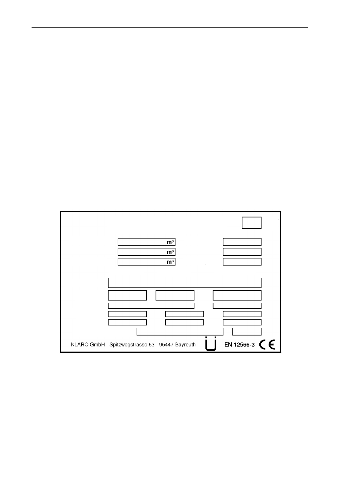
Plant Specifications
For any questions in the course of the operation of the plant, the specifications of your plant should
be noted as follows. With the help of this information, our staff will be able to help you more quickly
in the event of a malfunction. The specifications can be found on the nameplate, which is located
on the outside of the cabinet door for indoor cabinets, and inside the cabinet for outdoor cabinets.
Small Wastewater Treatment
Plant
KLARO GmbH
Original Operating Manual for KLARO Small Wastewater Treatment Plant V.15.07 3
CONTENTS Page
1. About this Operating Manual 6
1.1. Original Language of Documentation 6
1.2. Completeness 6
1.3. Liability 7
2. Safety 7
2.1. Explanation of Warnings and Prohibitions 7
2.2. Hazard statements 8
2.3. Warnings 9
2.4. Exclusion for Use 10
3. Warranty 10
4. Function of the SBR Plant 10
4.1. Plants for carbon elimination (process classes C) 11
4.2. Systems with Additional Nitrogen Removal (Process Classes N and D) 13
4.3. Systems with Additional Phosphate Elimination (Process Class +P) 13
4.4. Systems with Additional Sanitation (Process Class +S) 13
5. Control of the Small Wastewater Treatment Plant 13
5.1. Connections to the KL-controls (230V option for solenoid valves) 16
5.2. Connections to the KL24 controller(24V option for stepper motor valves) 16
5.3. Operating the Controller 18
5.3.1. Querying Operating Hours 18
5.3.2. Manual Control of the Valves and the Cabinet Fan in "Manual Mode" 19
5.3.3. Setting Date/Time 20
5.3.4. Set Holiday Mode 20
5.3.5. Query Malfunctions -Query Old Malfunctions 21
5.3.6. Display Settings 21
5.3.7. Service Menu and Action Code 21
5.4. Changing the Fuses 22
5.5. Operation of Power Failure Detector 22
6. Additional functions of the Controllers KLplus/ KL24plus and KLbasic/KL24base 23
6.1. Underload detection (KLplus/KL24plus) 23
6.1.1. Mode of Operation 24
6.1.2. Commissioning 24
6.1.3. Switching Off the Level Measurement 25
6.1.4. Safety and Fault Messages25
6.2. Optional Functions 26
6.2.1. Connection of an external alarm device 26
6.2.2. Connection of a contactor for switching the compressor 26
6.2.3. Connection of a UV reactor 26
6.2.4. Phosphate precipitation with metering pump 26
7. Maintenance, Repair and Operation 28
7.1. Sludge Evacuation 28
7.2. Operating Instructions 29
8. Fault Messages and Troubleshooting 31
8.1. Fault Message on the Display 32
8.2. Unusual Water Levels -Troubleshooting 33
KLARO GmbH
2Original Operating Manual for KLARO Small Wastewater Treatment Plant V.15.07
IMPORTANT:
•This Operating Manual contains information about the plant, from installation
to maintenance, and must therefore be read before commissioning of the
plant!
•All safety instructions must be observed!
•The Operating Manual must be kept readily available during the operation of
the plant!
Plant Specifications
For any questions in the course of the operation of the plant, the specifications of your plant should
be noted as follows. With the help of this information, our staff will be able to help you more quickly
in the event of a malfunction. The specifications can be found on the nameplate, which is located
on the outside of the cabinet door for indoor cabinets, and inside the cabinet for outdoor cabinets.
Small Wastewater Treatment
Plant
Original Operating Manual for KLARO Small Wastewater Treatment Plant V.15.07 3
CONTENTS Page
1. About this Operating Manual 6
1.1. Original Language of Documentation 6
1.2. Completeness 6
1.3. Liability 7
2. Safety 7
2.1. Explanation of Warnings and Prohibitions 7
2.2. Hazard statements 8
2.3. Warnings 9
2.4. Exclusion for Use 10
3. Warranty 10
4. Function of the SBR Plant 10
4.1. Plants for carbon elimination (process classes C) 11
4.2. Systems with Additional Nitrogen Removal (Process Classes N and D) 13
4.3. Systems with Additional Phosphate Elimination (Process Class +P) 13
4.4. Systems with Additional Sanitation (Process Class +S) 13
5. Control of the Small Wastewater Treatment Plant 13
5.1. Connections to the KL-controls (230V option for solenoid valves) 16
5.2. Connections to the KL24 controller(24V option for stepper motor valves) 16
5.3. Operating the Controller 18
5.3.1. Querying Operating Hours 18
5.3.2. Manual Control of the Valves and the Cabinet Fan in "Manual Mode" 19
5.3.3. Setting Date/Time 20
5.3.4. Set Holiday Mode 20
5.3.5. Query Malfunctions -Query Old Malfunctions 21
5.3.6. Display Settings 21
5.3.7. Service Menu and Action Code 21
5.4. Changing the Fuses 22
5.5. Operation of Power Failure Detector 22
6. Additional functions of the Controllers KLplus/ KL24plus and KLbasic/KL24base 23
6.1. Underload detection (KLplus/KL24plus) 23
6.1.1. Mode of Operation 24
6.1.2. Commissioning 24
6.1.3. Switching Off the Level Measurement 25
6.1.4. Safety and Fault Messages25
6.2. Optional Functions 26
6.2.1. Connection of an external alarm device 26
6.2.2. Connection of a contactor for switching the compressor 26
6.2.3. Connection of a UV reactor 26
6.2.4. Phosphate precipitation with metering pump 26
7. Maintenance, Repair and Operation 28
7.1. Sludge Evacuation 28
7.2. Operating Instructions 29
8. Fault Messages and Troubleshooting 31
8.1. Fault Message on the Display 32
8.2. Unusual Water Levels -Troubleshooting 33
3