Klaus Krick Modelltechnik roMarin ro1100 Instruction Manual

Congratula
t
of special f
u
A
t least 3 t
o
be availabl
e
General inf
o
The fire-fig
h
Co, Mainz-
M
that has ca
u
The exting
u
metres hig
h
The two 12
-
Technical d
Length app
r
Width appr
o
Draught ap
p
Displacem
e
Drive
t
ions on pur
c
u
nctions, req
o
4 ship mod
e
.
o
rmation ab
o
h
ting boat "
D
M
ombach, f
o
u
ght fire, oil
l
u
ishing moni
t
h
.
-
cylinder V-
e
ata
r
ox.
o
x.
p
rox.
e
nt approx.
© Kla
u
Buildin
g
c
hasing this
h
uires experi
e
els should a
o
ut the roma
D
üsseldorf" c
o
o
r use in the
l
eaks or a p
o
t
ors throw w
a
e
ngines of a
b
u
s Krick Mod
g
Instru
c
O
rd
h
igh-quality
m
e
nce in mod
e
lready have
rin fireboat "
o
mes from
a
Ruhr area.
T
o
rt facility at
r
a
ter or extin
g
b
out 930 kW
original
29.3 m
6.3 m
1.3 m
75.6 t
2x12-cyli
n
930 kW (
1
elltechnik, K
c
tion Fir
e
rd
er no. ro1
1
m
odel kit. Pl
e
e
l ship cons
t
been built a
n
Düsseldorf"
a
series of th
r
T
he boats ar
e
r
isk of explo
s
g
uishing foa
m
(1260 hp) t
o
n
der V-engi
n
1
260 HP)
Instruc
t
nittlingen, G
e
e
boa
t
Dü
s
1
00
e
ase note th
t
ruction. Thi
s
n
d also exp
e
r
ee identical
e
equipped
f
s
ion.
m
at 10.5 ba
o
gether give
2
7
9
n
es
2
t
ion Düsseldor
f
e
rmany
s
seldorf
at this kit, e
s
s
model is n
o
e
rience with
s
boats built
b
f
or disaster
s
r up to 95 m
e
the boat a s
p
model
1160 mm
2
50 mm
7
5 mm
9
kg
2
x Max Gea
f
Item-No. ro11
0
s
pecially the
o
t suitable fo
r
s
pecial funct
b
y Rheinwer
f
s
ituations; b
e
e
tres wide a
n
p
eed of abo
u
r electric mo
0
0 Rev. 1 St
a
installation
r
beginners.
ions should
f
t GmbH &
e
it a ship
n
d 45
u
t 37 km/h.
tors
a
tus 18.07.201
8
8

2 © Klaus Krick Modelltechnik, Knittlingen, Germany
Suitable remote control systems:
All remote control systems from two channels in the 2.4 GHz or 40 MHz band. Please contact your
dealer or www.krick-modell.de for the current offer.
For the expansion of the model with special functions we recommend the robbe Multi-Switch system in
conjunction with 8-channel systems of the Futaba F-14 system.
Accessories not included but required for driving operation to build the model:
piece. Description Part No. Order No.
2 Geared motor Max Gear 2.5:1 18f 42275
2 Interference suppression filter 21 42128
2 Shaft coupling 18e rb106-65
1 Steering servo 26 79059
2 drive battery, 6 V / 7Ah or 12 Ah 282 667255 or 667256
1 speed controller, from 30 A 283 67052
1 Receiver 284
1 Silicone cable 2-pole 1.5 mm² 163 67537
1 Motor connection Plug+socket round --- 67521
1 plug/socket Faston 6.3 mm insulated --- ro4039
1 Tam. Plug connection socket/plug --- 67513
Fitting set (BS), order no. ro1101
Contains all necessary small parts to decorate the model; e.g. fans, stairs, towing gear, life rings, lamps,
metal anchors, railing supports, signal horn.
Special function set (SFS), order no. ro1103
This set contains all the parts needed to install the special functions shown in the construction plans. For
example, the following functions are possible with these parts. Proportional horizontal and vertical pivoting of
the monitors. Connecting a fire pump, moving the boat crane, light bulbs to illuminate all lamps on board, etc.
Further accessories required for expanding the special functions can be found in
the information sheet included in the kit:
Please follow the instructions of the individual devices carefully!

© Krick Modelltechnik, Knittlingen, Germany 3
The size and equipment of the romarin fire-fighting boat "Düsseldorf" mounting box is ideally suited for
realising the many possible uses of the original also in the model. The fire monitors, crane, anchor windlass,
radar, headlight, blue light, horn and siren can be designed and installed in a functional way.
The thick-walled ABS fuselage is spacious enough to accommodate large drive batteries, powerful motors
and numerous units for special functions.
The two proven MAX Gear geared motors give the model good speed true to the original. Of course,
brushless direct drives can also be used. Four large rudders guarantee extreme manoeuvrability in forward
and reverse.
The three extinguishing monitors, which are assembled from prefabricated parts, can be swivelled
horizontally and vertically via the remote control. With the recommended electric gear pump you can spray
over a distance of approx. 6 metres.
With the finished sprayed boat crane, the deep-drawn rowing boat can be lifted from the afterdeck, swivelled
outboard and lowered into the water.
In addition to these main functions, it is also possible to carry out numerous other functional parts:
Radar, turn or swivel headlamps, blue light, switch position lamps on and off.
The parts contained in the set of fittings decorate the model perfectly. The special function set contains all
parts required for the special functions shown in the plan, with the exception of the specially offered items,
such as motors, batteries, etc.
Suitable and required tools:
Fretsaw with medium fine and fine blades, fretsaw table, glass paper of various grain sizes, wet sandpaper
fine, sandpaper file, balsa knife, order no. 416002 or 416005, holding clamps, screw clamps, pins, flat nose
pliers, screwdriver, drill, set of drills 1-10mm, set of paint brushes, small hammer, soldering iron with
accessories, side cutter, angle or triangle, one pack of strong rubber rings, approx. 120 x 10 x 1 mm.
Glues:
In the building instructions recommended:
UHU Acrylit or DELUXE Fusion Acrylit or Stabilit Express for wood, ABS, metal
UHU - Hart or Deluxe RC Modeller Power Adhesive for Wood - ABS
DELUXE Roket Rapid - Superglue for ABS - moulded parts.
Similar adhesives can also be used. The processing instructions of the individual adhesive manufacturers
must be observed. The instructions indicate where the individual adhesives are to be used. Allow adhesives
to cure well before starting the next work step.
General information on painting:
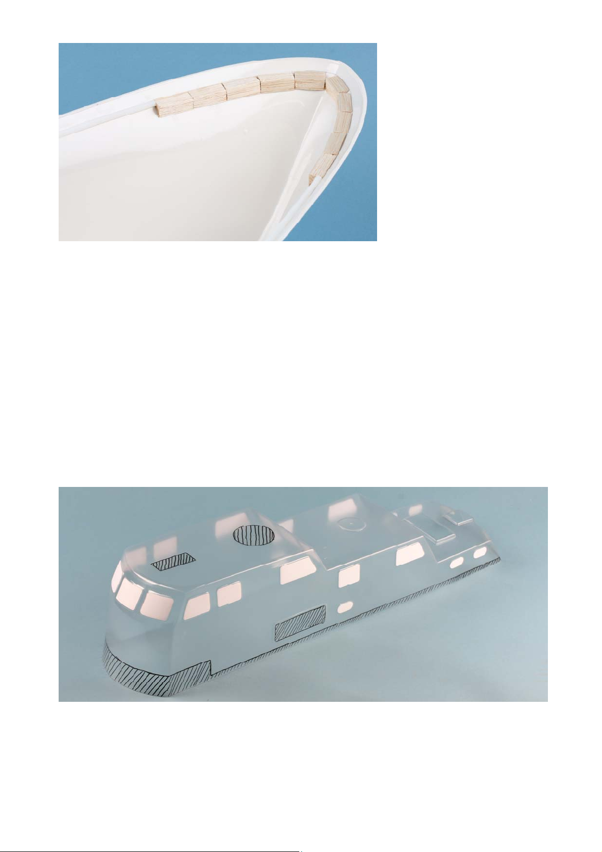
We generally recommend the exclusive use of synthetic resin varnish! All ABS parts must be washed with
synthetic resin thinner before painting and then touched as little as possible. All wooden parts, especially
parts that are no longer accessible after assembly, should be thoroughly brushed with pore filler 2-3 times
beforehand. Then slightly sand the adhesive surfaces again.
If you want a perfect and cleanly limited paint finish, you must always paint in sections, i.e. each individual
part that is to have a different colour shade is neatly matched to the model, then painted and then glued to
the model. However, if a part is painted in several colours, the demarcations must be made with special
masking tape, not crepe tape. The tape must be removed when the paint has dried. Do not allow to dry out. If
a lifelike coating is desired, you should use the image of the cardboard for the colouring.
Notes on the building plan and building instructions:
The small letters printed in bold next to the building plan texts are references which refer only to foreign-
language building instructions. Direction indications in the building instructions, e.g. on the right, can be seen
in the direction of travel. In the text, the BOM numbers of the part to be used are enclosed in parentheses.
The abbreviation BS shown in the parts list stands for fitting set, SFS for special function set.
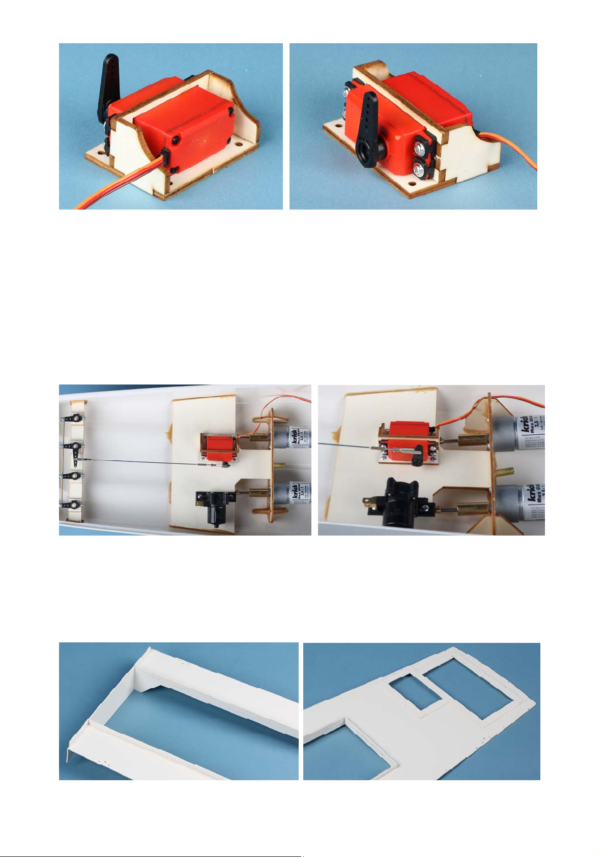
RC system
It is important to find out about the installation options of the planned RC system before construction begins.
If a remote control system other than the one suggested by us is installed, you can follow the installation
scheme. However, small differences in dimensions must be compensated for by yourself.
Make sure that the RC parts such as receivers, servos and speed controllers do not come into contact with
water. It is therefore advisable to arrange these parts high enough in the fuselage. This also applies to the
parts of the special functions.
General information for the construction process:
The numbering of the individual components essentially corresponds to the assembly described in the
instructions. Before starting construction, please read the entire construction manual in conjunction with the

4 © Klaus Krick Modelltechnik, Knittlingen, Germany
construction plans with the utmost care.
Use the parts list and the plans to get an exact overview of the various components and the construction
process. With the photos inserted in the text we give you information about the current state of assembly.
Parts or assemblies are partly unpainted for a better overview.
The installation of the respective special function is described at the corresponding point. However, this can
also be retrofitted.
Preliminary work:
Before starting work, check together with the BOM the completeness of the individual parts that are indicated
as belonging to the assembly in the BOM.
Carefully cut laser parts out of the laser plates with a sharp knife, deburr and re-drill holes if necessary. All
wooden parts must be sanded, especially at the edges, and primed two to three times with a pore filler
before installation or attachment.
Grinding work on ABS parts or on cut edges of glued together ABS parts must be carried out with fine wet
paper. All areas on ABS parts where bonding is carried out must be roughened up beforehand with coarse
abrasive paper.
Boat stand:
The first step is to manufacture the boat stand so that your model boat has a secure hold on the worktable.
First release the side parts (A) and support plates at the front (B) and rear (C) from the laser plate.
The boat stand can now be assembled and the support can be covered with felt or foam to protect the hull
surface.
The fuselage assembly
Hull:
The hull (1) made of ABS is roughly worked out with a knife or a fine jigsaw towards the contours visible on
the inside. Then use a file, planer or balsa knife and sandpaper to finish the contour of the fuselage exactly
to the mark so that no more bulges remain on the outside. (Section B-B, View Y).
A
A
B
C
1

© Krick Modelltechnik, Knittlingen, Germany 5
Then holes of initially Ø 3 mm are drilled in the markings for the anchor tubes at the bow, for the stern tubes
in the corrugated trousers, for the 4 rudders and only if an extinguishing pump is provided for the suction
tube at the keel outlet. Before the corresponding parts are installed, they are then drilled out to fit.
Now make the markings for the deck support strips (2) for the main deck. With the help of the device shown
in the picture, the dimension 7.5 mm is set (e.g. 3x3 mm strip between pencil and wide strip and hold
together with adhesive tape) and applied from the upper edge of the fuselage inside all around.
In the area of the transition between the main deck and the foredeck, the marking must be continued
according to the plan with the aid of a ruler. The deck support strips are glued in later.
Rudder:
Drill the 4 holes for the rudder to Ø 4 mm at the stern. Remove the support blocks (4) and glue them to the
fuselage 35 mm below the upper edge of the fuselage (acrylite) after roughening the bonding area.
1

6 © Klaus Krick Modelltechnik, Knittlingen, Germany
The rudder support board (5) is placed on the blocks, roughly aligned over the holes and muffled with
acrylite. The rudder guide tubes (7) (tubular rivet) are inserted into the retaining plates (6) up to the collar.
Now insert the tubes through the support plate (5) into the Ø 4 mm holes in the fuselage as shown in the
photo. The outer guide tubes should protrude about 3 mm from the bottom of the ship. First precisely align
one of the outer tubes in both directions (use the rudder). Secure the holding plates with a clip and glue the
tubes (7) and plates (5) firmly with acrylite. Proceed in the same way with the second, outer rudder guide
tube (View Y).
Then place the ruler under the fuselage on the outer guide tubes. Push the inner tubes through to the ruler.
Slide all oars in as help and align and glue the tubes as shown in the photo.
Next, shorten the Ø 3 mm brass shank of the rudder (8) to a length of 50 - 52 mm (deburr the interface).
Place the lower washers (9) on the rudder stocks and insert the rudders into the tubes (7). Now slide on the
sealing rings (10) from above and fit the upper washers (9). The rudder levers (11) are prepared according to
plan and photo 3. The unnecessary arms of the rudder levers are shortened or sawn off. The fourth hole is
drilled out to 3 mm. Then insert the adjusting rings (12) (7/3mm) and the hexagon socket head screws (13)
(M3x10) and place the rudder levers on the rudder stocks according to plan. Slightly tighten the screws by
hand. Align the rudders (8) and the rudder levers (11) exactly straight. Slightly press and tighten the levers
on the sealing rings. Pay attention to ease of movement. It must not be possible to move the oars up and
down in the pipe!
The crossbar 14 made of Ø 2 x 140 mm brass-wire is provided with 4 setting rings 15 (7/2) and screwed
under the rudder levers with screws 16 (M3 x 6) according to photo 3 and plan.
Then place the 4 rudder levers aligned with the rudders exactly parallel and tighten them with the screws 16
on the crossbar. The rudders must now all move easily to the right and left in parallel.
The steering linkage will be made later.
Drive installation:

© Krick Modelltechnik, Knittlingen, Germany 7
The motor bulkhead 17a with its longitudinal columns 17b is cut out of the laser plate. The motors are bolted
to the bulkhead and fitted with the coupling without the fixing foot on their end faces. For the suction pipe (if a
pump is mounted) a Ø 6 mm bore must be provided and widened to 7 mm. Fit the suction tube together with
the stern tubes.
Enlarge the holes in the fuselage shaft trousers to Ø 6 mm and insert the stern tubes into the fuselage. Align
so that the stern tubes protrude 85 mm from the corrugated trousers (see plan). Insert the ship's shafts and
tighten the couplings. Then glue the tubes and the motor bulkhead well with acrylite in the ground fuselage.
Fill the stern tubes with shaft grease GLS (or a few drops of thick oil) and insert the ship's shafts. Fit
propellers (20) Ø 40, 3-blade right and left (40 R and 40 L) with M4 brass lock nuts and check the shafts for
smooth running. Prior to installation, the motors must be fitted with filters (21) and connection cables (22)
about 150 mm long. Close the intake pipe watertight as a precaution.
Now staple the 4x4 mm deck support strips (2) with clips into the fuselage so that they are below the drawn
mark, i.e. 7.5 mm below the upper edge of the fuselage. Glue the strips into the fuselage with instant glue.
By swivelling the fuselage, the drops of adhesive run cleanly along the edge.
Then cut the short strip on the transom to length and glue it in place.
The slats on the foreship will be fitted later.
Mark the position of the auxiliary rubbing strakes (3) with a modified device 12 mm from the top edge of the
deck. Glue the 2 x 2 mm ABS profiles cut to length according to the plan as described. Glue the transverse
strip 3 to the rear as well. The skirting boards themselves are fitted after the fuselage has been painted.
Pump plate:
If you want to use the fire pump later, the suction pipe (23) must be installed now at the latest, since the
gluing points are later covered, i.e. subsequent installation is no longer possible.
The fitted and primed pump plate (25) is equipped with the steering servo (26) and the bracket (27)
according to the plan. For this purpose, the servo mount consisting of the parts (27a to 27c) is first mounted,
painted and the servo screwed in.

8 © Klaus Krick Modelltechnik, Knittlingen, Germany
The bracket is to be mounted with the Ø 2.9 x 6.5 mm self-tapping screws (28). The gear pump serves as an
extinguishing pump (29) and is fastened according to plan with the self-tapping screws (30) (Ø 2.9 x 9.5
mm). The pump must be equipped with a suppression set (31) and appropriate connection cables (22) in
accordance with the enclosed instructions. For special requirements it is also possible to install a second and
third pump.
The now completed pump plate must now be inserted according to the plan and photo and glued with
acrylite.
The next step is to make the steering linkage. The Ø 1.5 mm steel wire (32) is tinned cleanly at both ends.
Solder a clevis (33) at one end. Hook the linkage into the angle rudder lever 11.
The second clevis (33) with lock nut (34) and threaded bushing (35) is hooked into the servo-rod lever cut
according to plan. Determine the length of the boom (32). Cut the wire to length and solder in the threaded
bushing.
Main deck:
The edges of the main deck (36) are sanded all around, the glue edges are roughened. Proceed in the same
way with the long coaming parts (37) and the transverse edge (38). The hatch (39) and the boat hatch (40)
are carefully removed and also sanded and fitted.
Insert the coaming parts (37 and 38) into the deck and glue them together with cyano.
45
36
37 44a
44b
44c
44e
44f

© Krick Modelltechnik, Knittlingen, Germany 9
The deck is turned on its back (the hatch is then on the right in the direction of travel), the deck joists and the
cross beam are fitted and primed.
The hatch supports (44 a - e) for crane and boat hatches are manufactured from the 10 mm wide lasered
ABS strips. They are to be cut to length according to the plan and glued in place with superglue.
First lay the cross member (41) flush against the rear edge of the deck cutout and dimension the length so
that part (41) on the right and left is about 6 - 8 mm shorter than the deck width.
Glue with acrylite. Position the deck joists (42) flush with the cross member (41), saw in at a depth of about 3
mm at the "K" mark on the bend in the deck cut-out, carefully adjust the strip to the bend in the deck cut-out
and adjust the length. Now glue the deck joists cleanly with acrylite. When gluing, ensure that the deck rests
flat to prevent warpage.
Proceed as described with the hatch support (43). Here, too, the edge distance 6 - 8 mm must be
maintained. Select the position according to the plan so that the width of the rail reaches half into the escape
hatch and half into the boat hatch. Glue with acrylite.
Release and glue the top bulkhead (45). Glue the support (46) for the main deck in the left and right corners.
The front deck support (47) is adapted and glued according to the drawing. Prime the wooden parts well.
Make sure the seat is at a right angle. The completed main deck is now ready for installation in the hull.
Fit the deck exactly into the hull and on the support strips (2) and insert. Tighten the hull with rubber rings so
that it fits the deck without gaps. The bulkhead (45) must adapt precisely to the curvature of the side wall.
Place a drop of superglue in the joint between the hull and deck, starting on one side. By swivelling the entire
hull accordingly, allow the glue to run all around the joint between hull and deck. After one hour, repeat the
procedure again so that the joint is securely sealed and glued.
Foredeck:
As described for the strips (2), the 4 x 4 x 300 mm long ABS strips are also cut, adapted and glued here as
deck support strips (48). The markings for this have already been marked.
The balsa triangular strip (49) is used as deck support in the bow area. Depending on the radius of
curvature, this should be cut into pieces of approx. 10 - 30 mm in length. Glue the pieces in individually and
sand the deck surface carefully flat and horizontally.
The auxiliary rubbing strake (50) 2 x 2 mm is glued on the outside after marking, as described for parts 3.
Proceed particularly precisely in order to achieve perfect all-round bonding.
Prepare the foredeck (51). The part is carefully removed from the laser cut, as is the circular lid (52). Sand all
edges. In the bow area, a bevel must be ground so that the deck lies in the hull later without gaps. The Ø 8
mm holes for the anchor tubes are already drilled. Later they are then bevelled through the side of the ship to
their final size.
Align the bearing ring (53) on the underside of the deck and glue it with cyano. Primer and glue on tailored
deck joists (54).
The finished foredeck is fitted in like the main deck, held down with rubber rings and blocks and carefully
glued in with superglue.
Now the anchor tubes (55) can be installed. Use a Ø 4 mm drill to find the direction between the hole on the
front deck and in the side wall and then drill carefully in steps Ø 5 - 6 - 7 mm.
46
42
47
41
51
52
53
54
54

10 © Klaus Krick Modelltechnik, Knittlingen, Germany
Then insert the pipes (55) and mark the slopes. Remove the pipes and bevel the ends according to the
markings. Align the re-inserted pipes exactly and glue them well from the inside with acrylite. Finally, file the
transitions between the pipe and hull or deck cleanly and smooth them so that the pipes do not protrude and
the anchor chains do not get caught later.
The scuppers of the main deck are now being worked out.
With Ø 2.5 mm, drill several holes side by side and then file clean. The fuselage is finished and can be
painted according to the cardboard box. Please observe the painting instructions. If you want to recreate the
ribbed deck, get some fine tulle and cut it out according to the decks. The hatches (39) and (40) as well as
the lid (52) are covered with tulle. With the first coat of paint the tulle is glued to the deck parts. After the
second coat of paint, the ribbed deck structure is ready.
Cabin construction:
In the transparent cabin (56), all window sections are carefully covered with masking film to prevent
scratches. Furthermore, it makes sense to additionally cover the outside area with foil and adhesive tape to
protect it from further scratches or adhesive residues. This is not shown in the following pictures for better
illustration. The areas hatched in the photo must be roughly cut out. Cut the cut-outs for the slider housings
clearly within the marking.
Now the round and square cut-outs on the cabin ceiling as well as the lower contour must be sanded cleanly.
At the same time, the lower edge of the cabin is taken care of on the decks so that no gap is visible between
deck and cabin. If the cabin fits the decks exactly, the frame parts 58 are cut from 8 x 5 mm plywood strips,
primed and inserted according to the photo. Here, too, the bend "K" must be observed, as with the deck
girders (42). The slats must be sawed in accordingly. Glue the frame arch (59) into the arched front part of
the cabin. Finally, adjust the short frame pieces (58) and glue them in place.
49
48
1
56

© Krick Modelltechnik, Knittlingen, Germany 11
Then cut out the valve housings (57) according to the marking and cleanly grind the cut edges.
Place the enclosures in the cabin according to plan, cut AA, detail X and glue together. Grind the recesses in
the cabin flush with the inner surfaces of the valve housings.
If everything is well finished, the cabin can be pushed over the coaming with slight pressure. If necessary,
minor reworking should be carried out now.
If the cabin is seated correctly, mark the position of the frame arch (59) on the inside of the front deck by
transferring the inner contour of the frame to the front deck through the cabin ceiling.
Glue the holding block (60) to this mark according to the plan. This means that the cabin can no longer be
moved backwards. Cut the 8 x 5 mm support strips (61) to length according to the plan, prime and glue them
in place with acrylite according to the sectional drawing. Accordingly, the cross supports (62) must be cut
from 5 x 8 plywood strips, fitted free of tension and glued in place, unless special functional installation is
provided.
The ABS laser parts of the doors (63), (64) and (67) as well as the hatches (65) and (66) are machined and
adapted to the intended positions. We recommend that all doors are not glued on until the body and the
doors themselves have been individually painted.
At the end of this step, glue on the panels (68). The cabin roof (69) is cut out, neatly aligned and glued with
acrylite at the edges of the cabin ceiling. Now the shell of the model is finished and.
It is recommended to make the other assemblies and
the small parts of the boat, to adapt them to the body or
hull and to drill the corresponding holes. However, do
not install these parts firmly yet - this only happens after
painting. In this way you save yourself the tedious task
of masking before painting. Before painting, make sure
that the masking films of the windows are pressed well
on their edges again so that no paint can creep under
them.
56
58
58
59
61
62
57
69

12
Anchor wi
n
The 3 winc
h
If necessar
y
Cleanly sa
n
Now bend t
them into t
h
to the axle
(
chain whee
rotate easil
y
knob (81).
Drill Ø 3 m
m
stoppers (8
3
the crank.
F
Glue under
positioning
capstan he
a
If the windl
a
In the other
and glue th
e
Working
In order to
a
only one a
n
n
dlass:
h
housing p
a
y
, re-drill the
n
d and prim
e
he 3 cranks
h
e axles (71)
(
78) and fit
a
l with axle,
p
y
inside the
h
m
for the ch
a
3
). First drill
F
it the crank
s
the 4 x 4 m
m
are adjuste
d
a
d through t
h
a
ss is to be
d
case now p
e
m in the ch
a
anchor w
a
void entan
g
n
chor functio
n
91
92
95
a
89
88
© Kl
a
a
rts (70) are
d
Ø 2 mm hol
e
the part. Af
t
(74) accordi
and (76). S
o
a
washer (79
)
p
ush on the
s
h
ousing. Th
e
a
in links (82)
the holes in
s
(84) with 2
m
ABS unde
d
so that the
a
h
e chain sto
p
d
ismantled, t
rovide the t
w
a
in pins 82 (
indlass f
o
g
ling of both
a
n
al.
96
a
90
a
us Krick M
o
d
etached fr
o
e for the cra
t
er the base
ng to the dr
a
o
lder the se
c
)
. Insert the
s
s
econd was
h
e
n fit the pre
-
according t
o
the longitud
i
sleeves (75
)
rlay (85) ac
c
a
nchor chai
n
p
pers to the
he following
w
o anchors (
8
UHU hart).
o
r one an
c
a
nchor chai
n
o
delltechnik,
o
m the laser
nk shaft (71
)
plate (73) h
a
a
wing, solde
r
c
ond sleeve
(
s
leeve (72) i
h
er (79) and
g
-
assembled
c
o
the plan an
i
nal directio
n
)
each and s
c
ording to th
e
n
s can be g
u
anchor tube
s
section mu
s
8
6) with 100
c
hor
n
s in later fu
n
T
h
th
i
G
l
fr
a
th
e
b
e
bl
o
s
h
st
a
88
98
99
97
1
Knittlingen,
G
plate and gl
u
)
and the Ø
2
a
s been glu
e
r
or glue the
m
(
72) to the a
x
n
to the winc
h
g
lue on the
c
c
rank axles
(
d glue on th
e
n
Ø 3 mm, th
e
l
ide them int
o
e
detailed dr
a
u
ided in a str
a
s
(55).
s
t be followe
d
mm chain (
8
n
ctional ope
r
h
e right anc
h
i
s case, the
l
l
ue the laser
e
a
me (89) an
d
e
plan. Finis
e
easily inse
r
o
cks (92) wi
t
h
orter slots o
a
nd (94) wit
h
9
103
1
17
G
ermany
u
ed together
2
.5 mm hole
e
d on, paint t
h
m
to the han
x
le (76). Glu
h
housing (7
c
apstan hea
d
(
71) and (76
)
e
rivet. Now
e
n drill the
Ø
o
the right a
n
a
wing. The
s
a
ight line fro
d
.
8
7) each, pu
r
ation, it is r
e
h
or is shown
l
eft anchor
m
e
d base pla
t
d
the upper f
h the base
p
r
ted into the
f
t
h reinforce
m
f the base p
l
h
reinforcem
e
89
6
102
(UHU hart).
for the one
s
h
e finished
h
dles (75) an
d
e the chain
w
0), push thr
o
d
(80). The
u
)
and insert
t
remove the
Ø
2 mm cros
s
n
d left chain
s
lope to the
d
m the sproc
k
ll them in as
e
commende
d
functional in
m
ust be shut
t
e (88) to the
rame (90) a
c
p
late (91) so
t
f
rame. Glue
m
ent strips (
9
l
ate. Glue th
e
e
nt strip (93
)
92
s
leeve 72.
h
ousing.
d
insert
w
heel (77)
o
ugh the
u
nit must
t
he gear
chain
s
hole for
stoppers.
d
eck and th
e
k
et and
planned
d
to make
the plan. In
down.
lower
c
cording to
t
hat it can
the bearing
9
3) into the
e
motor
)
into the
90
94
9
5
e
5

© Krick Modelltechnik, Knittlingen, Germany 13
larger slot.
Suppress the gear motor (95) (reduction 400:1) and solder about 300 mm of cable.
Then screw the motor (95) to the motor stand using M 1.6 screws.
Ream the washers (96) and (97) with Ø 3 mm. Place one large and one small disc each on the Ø 3 mm axle
(102) and glue them together to form stepped discs. Glue the driver plate (98) twice to one disc on the small
disc (97). Drill 3 mm Ø into the plastic tube (99) for the threaded pin of the adjusting ring (101) and 1.5 mm Ø
for the split pin (100), insert the split pin (100), shortened to about 10 mm, bend it apart inside and glue it
together.
Now glue the step pulleys with inserted adjusting
ring (103) and the tube at right angles to the drum.
Then mount the unit with the Ø 3 mm brass axis
(102) between the base plates (92). Cleanly align
the winch unit, check that it runs smoothly and
connect the motor support to the geared motor (95)
and coupling hose (95a).
(Disassembly: Loosen the adjusting ring, pull out the
shaft (102) and remove it from the motor).
The sash fastener (104) with the Ø 2.2 x 6.5 mm,
self-tapping screw (105) is fitted in the reinforcement
strip (93) for securing. A corresponding slot is
provided in the base plate (88). The winch is now
complete and can be installed in the fuselage. It is
recommended that the base plate with the frame is
glued in on its own (acrylite) and the winch is
inserted later. Separate 10 cm from the chain for the
fixed anchor side. Thread the long chain piece on
the functional side according to the plan and fasten
it to the anchor and winch.
The electrical connection to the RC system is made
later.
Notes on fire-fighting monitors.
Assembling the monitors is not particularly difficult, but since they cannot be retrofitted for special functions, it
should be determined beforehand which of the possible functions are to be carried out.
It is shown and described:
Function 1: Proportionally controlled, horizontal pivoting with the aid of a normal servo
(pivoting range of the monitors: 270°)
Function 2: Proportionally controlled lifting and lowering of the extinguishing pipes with another, normal
servo.
Function 3: Connecting an extinguishing water pump.
It is recommended to paint the handwheels and straightening levers before assembling. The instructions and
the plan explain the fully equipped monitors.
Monitor A
At the beginning the grating for all three monitors are built and painted together. Remove the grating frames
(106) for monitor "A", (107) for monitor "B" and (108) for monitor "C" from the laser parts and grind them
cleanly. Paint the part (106) red, the parts (107) and (108) beige. The frames contain markings for the
position of the innermost strips.
The 1.5 x 5 mm linden strips (109) are first primed twice.

14
Then cut th
e
an even di
s
Cut and gri
n
The gangw
a
In the case
shown in th
Rotate the l
Now align t
h
For secure
f
self-tappin
g
the cover
w
been remo
v
foot on the
c
and photo).
Then mark
(Mo2) is no
w
to remain ri
g
the foot).
Now solder
protrudes a
1 mm tube
s
tube, which
Now place
t
mm hole of
The pipe h
o
the extingui
(Mo9) mad
e
in the rotar
y
A
djust the
p
together wi
t
(Mo12) into
glue on the
Insert the s
p
for monitor
slipping wit
h
A
piece of
w
hook into t
h
fits easily i
n
Cut off the
e
The spring
i
107
e
strips roug
s
tance betw
e
n
d the strip
e
a
y is made f
r
of grating "
A
e plan.
asered lid (
5
h
e grating "
A
f
astening of
g
screws (11
0
w
ith Ø 2.5 m
m
v
ed from the
c
over and al
the 3 holes
o
w
screwed t
o
g
id, then dril
the guide tu
bout 5 mm f
r
s
o that the fi
should not
r
t
he rotary h
e
the rotary h
e
o
lders (Mo7)
shing water
e
of aluminiu
y
head and i
n
p
arts so that
t
h a small dr
o
the slots of
varnished s
t
p
iral spring (
"A", and pla
c
h
a drop of s
w
ire that is b
e
h
e end of the
n
to the Ø 7
m
e
nd of the h
o
i
n the hose
p
© Kl
a
hly to lengt
h
e
en the strip
s
e
nds on the
o
r
om the sa
m
A
" (106), rec
e
5
2) on the fo
r
A
" according
the cover a
n
0
). For this
p
m
. Insert the
deck from b
ign it so tha
t
o
f the foot o
n
o
the cover
w
l out the be
a
be (Mo5) o
n
r
om the sha
f
ne hole at t
h
r
ub through!
e
ad (Mo6) o
n
e
ad. Glue s
h
are to be gl
u
pressure is
a
m pipe, the
s
n
the pipe h
o
they can be
o
p of super
g
the rotary h
e
t
raightening
Mo14) (Ø 3.
2
c
e the hose
o
uperglue an
d
e
nt into a s
m
hose and p
u
m
m tube.
o
se so that t
h
p
revents it fr
o
Rest 1 m
a
us Krick M
o
h
according t
o
s
, hold a 1 m
o
uter contou
m
e slats (109
)
e
sses must
b
r
ebody so th
to the plan
s
n
d the later
m
p
urpose, the
bearing bus
h
elow as cen
t
t
the housin
g
n
the cover
a
w
ith M 2 x 1
0
a
ring bushin
g
n
top into the
f
t. Cut off th
e
h
e edge is ni
c
n
the shaft (
M
h
aft and hea
d
u
ed cleanly
a
a
pplied to th
e
s
pray nozzl
e
o
lder so that
easily move
g
lue. Check
a
e
ad, align th
e
lever (Mo13
)
2
x 60 mm)
i
o
n the conn
e
d
then pull it
m
all hook at t
u
ll in the ho
s
h
e hole in th
e
o
m buckling
.
1
m
o
delltechnik,
o
the photo
a
m thick ABS
r and the in
n
)
according t
b
e provided
f
at the deck
s
s
traight and i
m
ounted mo
n
lid and deck
h
ing (Mo1) i
n
t
ring. Glue t
h
g
(Mo3) poin
t
a
nd drill Ø 2
m
0
brass scre
w
g
(Mo1) (A 2
monitor sh
a
e
bottom Mo
5
c
ely smooth
.
M
o4) so that
t
d
together w
i
a
nd precisel
y
e
m later. In
s
e
(Mo10) an
d
the thin tub
e
d up and do
w
a
gain for ea
s
e
m at an an
g
)
.
i
nto the silic
o
e
ction nipple
into the mo
n
he end is re
c
s
e. By slightl
y
e
front of th
e
.
Check eas
y
1
09
Knittlingen,
G
a
nd glue the
m
waste piec
e
n
er, round o
p
o the plan.
f
or the faste
n
s
tructure (tul
n the middl
e
n
itor, the ent
i
are drilled t
o
n
to the Ø 15
h
e housing (
M
t
s exactly in
t
m
m. If the m
w
s (111) an
d
mm) under
t
a
ft (Mo4) (for
5
flush, but
d
.
(Later, a n
y
t
he thin tub
e
i
th superglu
e
y
with super
g
s
ert the foam
d
glue (supe
r
e
(Mo5) is on
w
n, and the
n
s
e of movem
e
g
le to the re
a
o
ne hose (M
o
of the pipe
h
n
itor shaft.
c
ommended
y
stretching
t
e
hose does
n
y
movement
G
ermany
m
to the gra
t
e
in between
p
ening.
n
ing screws
(
le) matches
e
. Glue the li
d
i
re assembl
y
o
gether with
mm openin
g
M
o3) to the
b
t
he direction
onitor "A" is
d
M2 nuts (1
1
t
he ceiling!
a
monitor "A"
d
o not solder
y
lon thread i
s
e
(Mo5) lies l
a
e
.
g
lue. The se
a
pipe (Mo8),
r
glue). Place
the left in t
h
n
glue the pi
p
e
nt. Now in
s
a
r and glue t
h
o
15), which
i
h
older. Secu
as an aid fo
t
he hose dia
m
n
ot leak.
of the entire
t
ing frames.
.
(
110) at the
p
the structur
e
d
and gratin
g
y
is fastened
Ø 1.5 mm.
T
g
in the cove
b
ase (Mo2).
of the grati
n
to be pivote
d
1
2). (If the m
a
nd screw it
t
120 mm lon
g
it. Cleanly
d
s
passed thr
o
a
terally left i
n
a
ms must b
e
the extingui
the pipe be
n
h
e direction
o
p
e holder an
s
ert the two
o
h
em togethe
r
i
s about 300
re the hose
r pulling in.
H
m
eter decre
a
extinguishi
n
T
o achieve
p
oints
e
on the lid.
g
together.
with the 3
T
hen drill ou
t
r which has
Place the
n
g. (see ma
p
d
, the base
onitor "A" is
t
ogether wit
h
g
) so that it
d
eburr the Ø
o
ugh this
n
the Ø 7
e
sealed, as
shing pipe
n
ds (Mo11)
o
f injection.
d pipe bend
o
utriggers
r
. Finally,
mm long
against
H
ang the
a
ses and
n
g head, as
t
p
h

© Krick Modelltechnik, Knittlingen, Germany 15
well as the tightness of the water-carrying parts. Screw the M 2 x 4 screws Mo16 into the outriggers.
The transverse bearing (Mo17) from the Ø 2.5 x 8 mm brass sleeve is drilled through Ø 1.5 mm transversely.
Now cut the setting lever (Mo18) from Ø1 mm brass wire to 90 mm and form the hook according to plan.
Hook the setting lever onto the knee of the pipe support (Mo7) and fit the cross bearing and pipe rivet
(Mo19). Then hang the cross bearings between the outriggers.
Bend the rear eye of the tension spring (Mo20) so that it can be pushed over the setting lever (Mo18) as
shown in the drawing, hang the front eye in the hook of (Mo18).
When in perfect working order, the quenching head always lifts to the position of the highest pipe elevation.
Drill the Ø 7 mm handwheel (Mo21) in the middle Ø 1 mm and slide it onto the end of the setting lever. If the
height adjustment is to work, the Ø 0.25 mm Perlon thread (Mo22) (500 mm long) is clamped with the small
handwheel and threaded through the thin brass tube (Mo5). Now swivel the erase head to the lowest
position and advance the handwheel (Mo21) to the rivet (Mo19).
Shorten the protruding setting lever. The erase head "A" can now be checked manually for all movement
functions.
The handwheel (Mo23) as well as the valve lever (Mo24) will be used later.
Make sure that everything can be moved easily.
The extinguish heads for the monitors "B" and "C" are assembled in the same way. Only the lengths of the
following parts must be observed:
Monitor shaft B (Mo4) = 175 mm long Guide tube B (Mo5) = 180 mm long
Monitor shaft C (Mo4) = 125 mm long Guide tube C (Mo5) = 130 mm long
Function upgrade for monitor A
Detach and assemble the two servo mounts (113) for
the swivel servo and (114) for the lift servo and the
spacer plates (115). According to plan, glue parts 113-
115 on a flat surface to a right-angled frame (UHU hard).
Glue the servo frames 120 and 125 together from their
respective parts a, b and c according to the illustration
and glue them flush with the upper edge to the plates
(113) and (114).
Insert the erasing head "A" into the foot Mo2 on the cover
52 and align the primed frame with bearing bush Mo1
according to the monitor shaft Mo4.
125 115
116
Mo4
Mo15
Mo22
118
119
127

16 © Klaus Krick Modelltechnik, Knittlingen, Germany
Glue the bearing bushes and frame (superglue) so that the extinguishing head "A" can be turned easily.
Make sure that the frame is about 10 mm from the front and rear edges of the cover (52) (drawing). Sand the
bearing bush laterally flush with the servo plates (113) and (114).
Now fix the Ø 28 mm belt pulley (116) with the M 3 x 6 grub screw (117) on the pipe (Mo4). Fit the tubular
rivet (118) and secure with a drop of "UHU hard". The purpose of the tubular rivet is to protect the nylon cord
at the deflection from chafing.
The control disc (servo disc) supplied with the servos is now screwed twice to the large Ø 68 mm belt pulley
(119) (M 2 x 6 screw (213) and M 2 nut (112)).
Mount the swivel servo (121) in the holder (120) according to the plan and photos and fit the disc (119).
The unit should be positioned (plan + photos) so that the pulleys are at one height and at least 5mm apart.
Now loop the belt pulleys with the cord (123) once or twice according to the extra illustration and knot the
tension spring (124) between them with little tension. Set the servo and erase head to neutral and push the
spring to the position indicated on the plan. The monitor A is now ready for horizontal swivelling.
Mount the lift servo (126) in the holder (125). Fasten the perforated, one-sided lifting lever made of ABS
(127) to the servo disc with a screw (128). The lever (127) is set later. The unit according to the plan and
photos should be aligned so that the lever is at the same height as the edge of the tubular rivet (118). Fix the
holder and fasten it with self-tapping screws (122). Move the lift servo with the RC system to the position in
which the highest pipe elevation of the monitor "A" is to be achieved. Insert the Perlon thread Mo22 into the
inner hole Ø 1 mm (small stroke) of the lifting lever and fix it with the clamping screw (129) with U-disc (130).
Now move the servo in the opposite direction to the stop and check whether the erase head has reached the
lowest point.
Insert the complete monitor "A" assembly in the boat, screw on the cover and check its function with
transmitter and receiver. The final connection is made later, as is the connection to the pump.
Monitors B and C:
After the monitor "A" is ready for use, the two monitors "B" and "C" are now mounted on the cabin 56, which
is ready for use. They are removed again later, before painting the cabin. The ABS disc (131) (Ø 48 mm) is
cut out. Under the prefabricated grating "B" (107) the red lacquered disc is aligned and glued. Center the foot
(Mo2) with the aid of the bearing bush (Mo1), align it as shown on the grating and drill Ø 2 mm through the
washer (131). Align the grating "B" on the roof of the cabin exactly, drill the Ø 2 mm holes. In the middle of
the Ø 15 mm hole (part 131) drill through the roof step by step to Ø 8 - 10 mm. Screw on foot and grating
"B". (screws (111) and nuts (112))) Drill into the centre of the platform for monitor "C" Ø 8 - 10 mm in steps.
The foot "C" is aligned in its position and bolted as for "B".
Then remove the servo plate (132). The recesses for the servos may need to be widened so that the
intended steering gear with the output is at the marked point on the plate. (The distances between the
moving parts and the sides of the cab must be sufficiently large).
Double up the plywood spacer blocks (133) 5x8 mm to obtain a height of 10 mm. Glue these for the lift servo
(134) and prime the whole plate (132). Insert the plate into the cabin, push it backwards and align it with the
monitor shafts "B" and "C" (Mo4) so that they are approximately in the middle of the corresponding recess.
Fix the plate with acrylite. Then place the bearing flanges Mo1 (Ø 2.5 mm boring) on the pipes Mo4 and align
them so that the extinguishing heads "B" and "C" are very easy to turn. Fix with superglue and fasten the
flanges with the screws (135).
To prevent the monitors from moving upwards, they are secured with the 15/7 adjusting ring (136) and the M
3 x 6 grub screw (117). Now the lift servo (134) and the swivel servo (137) can be inserted and screwed in.
(8 pcs. Ø 2.9 x 6.5 self-tapping screws (122)). Mount the pulley Ø 68 mm (119) as for monitor "A" and place
it on the swivel servo. Align the Ø 28 mm belt pulleys and screw them together. (grub screw 117) . Finally,
attach the scale cord with spring (124) according to the construction plan. (See figure on plan 2: One or two
full surrounds on all discs!

© Krick Modelltechnik, Knittlingen, Germany 17
Set the extinguishing heads "B" and "C" so that the servo swivels them evenly and together to the left and
right.
Place the lift lever (138) on the servo disk of the lift servo (134) and screw in the clamping screws Ø 2.2 x 6.5
mm (129) with washers (130). Attach the tube rivets Ø 8 x 8 (118) to the monitor shafts (Mo4) so that the
nylon thread (Mo22) does not rub against the tubes. Then thread the yarn from both monitors according to
the drawing in the lever, the extinguishing heads are in the highest position and move the servo to the
corresponding position. Carefully clamp the nylon threads and move the servo to the "low" position,
observing the erasing heads. When correctly arranged, the pipes swivel together from the highest to the
lowest position. If everything works, the lifting lever and servo disk are glued and secured with the fourth
screw (129). The monitors "B" and "C" can also be moved.
The connection to the pump is made later.
Now completely disassemble the monitors "B" and "C" so that they are not damaged during further
assembly. The grating "B" is screwed back onto the cabin to prepare the circular handrail.
Handrails and cabin rails
If necessary, the retaining straps on the grating "B" are drilled out to Ø 2 mm.
Now drill carefully, exactly vertically, into the cabin roof. The supports (139) are first sawn off from Ø 2 mm
brass-tube with overlength. Then insert the supports into the grating and roof.
To make the grating even, it is aligned as shown in the photo, using a ruler. Now adjust all supports to a
height of 33 mm (height corresponds to the inserted railing support). Do not stick supports together.
Cut the 2 handrails (140) to 350 mm length and then bend them in one plane according to the photo (I.).
65 mm 50 mm
Mo1
132
133
119
134
116
137

18 © Klaus Krick Modelltechnik, Knittlingen, Germany
Wire bent around a core with Ø 65 mm (e.g. spray can), gives the desired Ø 125 mm. Thread the 5 pins
(141) onto each handrail and insert them into the supports 139.
The handrail is carefully aligned and everything is soldered (II.)
Only then bend the two 50 mm (to the front) and 65 mm (to the rear) long ends into the final shape. (III.)
Carefully remove the handrails and grating "B" and reassemble and glue them only after painting.
The rear handrail (142) on the monitor "C" is manufactured as described. (plan and photo 20).
The assembly of the side railing at monitor "C" can be seen from the plan and the following view photos. Drill
out the 8 rail supports (143) in the upper ball Ø 1.6 mm.
Drill the Ø 1.2 mm holes in the cabin and insert the railing supports. Cut the lower rail draw 144 from Ø 0.7
mm brass wire, insert it into the supports and insert it into a corresponding hole in the front of the
superstructure. Carefully solder the tension and supports or glue them together with superglue. The upper
rail tension (145) is bent from Ø 1.5 mm brass wire according to plan, inserted into the supports and into the
superstructure and soldered to the supports. Remove railing parts for painting.
The handrails running around the cabin are manufactured as follows: The handrail (146) is bent from Ø 1.5
mm brass wire. 5 Slide on pins (141) and attach spacer sleeves 147 (Ø 2 x 3). Angle and solder splints
according to plan, mark and drill Ø 1 mm holes in the cabin. Check the exact fit of the handrail.
Align the handrails (148) left and right in height according to the connection of the front part (146) and fit
them together as described above. One sleeve (147) each serves as connecting part between the handrails
(146) and (148).
(plan and photo). The other handrails (149) (left and right) and (150) are manufactured as described.
Remove all handrails for painting. Bend the door handles (151), the step bars (152), the handles (153) and
the handle bars (154) from Ø 1 mm brass wire, drill holes in the cabin and put them on a piece of balsa wood
for painting.
Some of these wire parts are only needed later.

© Krick Modelltechnik, Knittlingen, Germany 19
Mast:
The two halves of the mast (155) are glued together and sanded down according to plan. A fine groove can
be worked into the back, in which the cables for the lamps are later laid. Prime the wooden pole. Cut out the
base frame (156), the small lamp shelf (157) and the large lamp shelf (158), as well as the antenna holder
(159).
Bend the antenna wire (160) from Ø 1.5 mm brass wire. Place the parts (158), (159) and (160) on a plastic
foil and glue according to plan (superglue). Adjust and glue the base frame and the lamp shelves to the
mast. Drill the Ø 3.5 mm hole for the blue light base (161) at the top of the mast and insert the base.
The complete mast is now aligned on the cabin roof and installed with 2 screws Ø 2.2 x 6.5 mm (110)
according to the plan. Prepare bulb (162). If necessary, extend the connecting wires in the visible area with
appropriately cut twin wires (163) (cross-section 2 x 0.07 mm²). Insulate the bare wires and solder joints with
paint or heat-shrink tubing. Insert the bulbs (162) for blue light (164) and position lamps (165) on the mast
and secure with UHU hard adhesive. The blue light is later connected to the turn signal or speed camera
electronic module (166) in the cabin. Here it is recommended to solder a BEC socket with cable to the wires
Ø 0.07 mm², which can then be plugged directly into the module (166).
Only the lamps that are to light together should switch in parallel and later wire them in the cabin with the
other lamps.
If the cables are neatly laid and glued to the rear edge of the mast, the light bulbs are covered with adhesive
tape; the mast is painted. Solder the FM antenna made of brass wire Ø 1 x 50 mm and the tubular rivet (167)
together. Stick the lamps and the VHF antenna to the completed mast.
Typhone, headlight, loudspeaker
For the typhon (168), the base (169) is formed from a plywood block so that the bell stands horizontally. Glue
the pedestal to the cabin roof, glue on the typhon later
Headlights and loudspeakers are mounted in one unit and can be swivelled horizontally. Insert a 6 V
precision lamp (162) into the headlamp. The loudspeaker holder (171) is drilled through Ø 2.5 mm, the
headlight housing Ø 1.8 mm. The parts are screwed together with the sheet-metal screw (172) (Ø 2.2 x 6.5
mm).
Insert the speaker (173) into the eyelet of the holder and glue it together. Insert into the headlight holder
(174) swivel axis (175) and glue together. Guide the lamp connection downwards through the axle. At the
appropriate point, drill through the cabin roof and ceiling vertically Ø 3 mm and insert the unit with spacer
(82). The loudspeaker/headlight unit is pivoted using an eccentric. Fit the eccentric lever (176) with 7/3
adjusting ring (177) and grub screw (M 3 x 6) (117). Cut the lever according to plan and fasten an M 2 x 10
bearing screw (128) with nut (112) in the central bore. Place the lever on the swivel axis and tighten slightly.
The 1000:1 crimped, interference suppressed micro geared motor (178) with approx. 300 mm cable is
screwed onto the ABS motor plate (179) with M 1.6 screws. Screw the plate onto the 5 x 15 x 20 mm bearing

20 © Klaus Krick Modelltechnik, Knittlingen, Germany
blocks (180) using two Ø 2.2 x 6.5 mm self-tapping screws (129). Glue the whole unit under the cabin ceiling
according to the plan. Now measure the distance between swivel axis and motor shaft. The eccentric rod
(181) made of brass tube and 2 eye bolts (182) must be adjusted to this length and soldered. Drill the eye
bolts (182) to Ø 2 mm and flatten the thickening. The actuator lever is soldered together from a 7/3 adjusting
ring (183) with M 3 x 3 grub screw (101), an eye bolt (102) and an M 2 x 10 screw (128) according to
drawing. It is recommended to file a small groove into the adjusting ring, then the eye bolt can be soldered
better. The screw head must also be soldered. Now place the drive lever on the motor in such a way that the
grub screw engages in the flattening of the motor shaft. Hook the eccentric rod (181) onto the drive lever and
eccentric lever and lock with 2 nuts (112) each so that everything moves easily. Remove the
loudspeaker/headlamp unit until after painting has been completed.
Radar
For the device shaft (184) made of Ø 8 mm brass pipe, drill a corresponding hole vertically through the cabin
roof and ceiling and insert the shaft. Then screw the 6 V micro geared motor (185) (400:1) onto the motor
plate (186) as already described. Glue two 8 x 5 x 35 plywood blocks (187) on top of each other, screw to
part (186). Glue the interference suppressed and cabled complete unit to the ceiling exactly in the middle
under the device shaft. As coupling (188), between motor and radar shaft (189) (Ø 2 mm brass-wire) serves
a piece of rubber hose. Cut the shaft to excess length, slide on the hose and place it on the motor shaft.
Mark the shaft about 5 mm above the upper edge of the finished tool shank, remove and saw off. The radar
head from the pipe section (190) and the laser parts (190a + 190b + 190c + 190b). If necessary, drill out the
radar head a little so that the 2 mm shaft can rotate freely.
The radar reflector 191 is filed, ground and painted according to plan and provided with a bore for the shaft.
Then stick to the shaft. After painting the cabin, place the entire radar unit on the motor shaft and it is ready
for operation.
Lamps
Assemble the left and right lamp board from the laser parts (192a + 192b + 192c) in mirror image (one right
and one left) and stick it onto the shaped platforms of the roof. Solder the tail light (193) to the curved and Ø
2.5 mm drilled holder (194) and fix it to the cabin after painting with a Ø 2.2 x 6.5 tapping screw (110).
Also fit the bow light (195) with holder (194) and prepare it for later gluing to the flag pole holder (221). The
last lighting unit to be fitted is the anchor light (196) with a light bulb (162) and attached to the Ø 4 mm lamp
holder (197). Drill the corresponding Ø 4 mm hole in the roof and cabin ceiling.
Ventilators
In the next section, the ventilators are prepared and assembled. They are also painted separately and later
glued to the cabin. For the air scoops (198), drill the Ø 8 mm holes in the side lights. The hats are later put
through the roof so that they stand on the ceiling of the cabin. Glue the shaft (200) (round wood) into each
disk ventilator (199). Drill into the cabin of the Ø 12 mm hole step by step. The ball ventilator (201) is glued to
the Ø 8 x 85 mm fan tube (202). It is recommended to glue a small plywood board under the cabin ceiling as
reinforcement.
The mushroom ventilator 203 is composed of the discs and rings (203a + 203b + 203c + 203c+ 203c) and
sanded clean on the outside. Glue to a piece of round wood Ø 8 mm.
The Ø 7 x Ø 5 x 45 mm plastic pipes 205 are attached to the suction fans 204, glued and ground. Here, too,
a reinforcement board is recommended.
Towing gear
The towing gear is assembled according to the extra drawing. The steel wire (206) is to be bent like a "V".
Hook the longer leg of the spring into the bolt (207). Insert the unit into the swivel arm (208) using the M 2 x 6
screw. Sand the hook (209) laterally so narrow that it does not get caught on the spring. Fix the hook easily
with the 2nd screw. Insert the towing gear with bearing pin (210) and washer (211) (Ø 6.3 x Ø 2.6 mm) into
the corresponding bearing ring on the cab and tighten with nut (212) (M 2.5). Test full mobility. The towing
hook is triggered by the lifting servo of the monitors B and C. When the two monitors are in the highest
position, the tow hook opens when the trim is switched on at the transmitter.
The nylon cord (238) is guided to the lifting lever by the latch (207) of the towing gear. Set the cord length so
that the release functions as described above.
Finishing work on the cabin.
Solder the whip antenna (214) made of Ø 0.8 mm steel wire with 5 brass sleeves (75) (Ø 2 x 8 mm) and
insert another sleeve Ø 2 x 3 mm (147). As base (215) the Ø 2 x 12 mm tubular rivet is soldered with 2 split
Table of contents