CANX3-KIT
Installation and Operation Manual
Go to Table of Contents PG 5/44 REV: A (9/4/2020)
1. LIST OF FIGURES
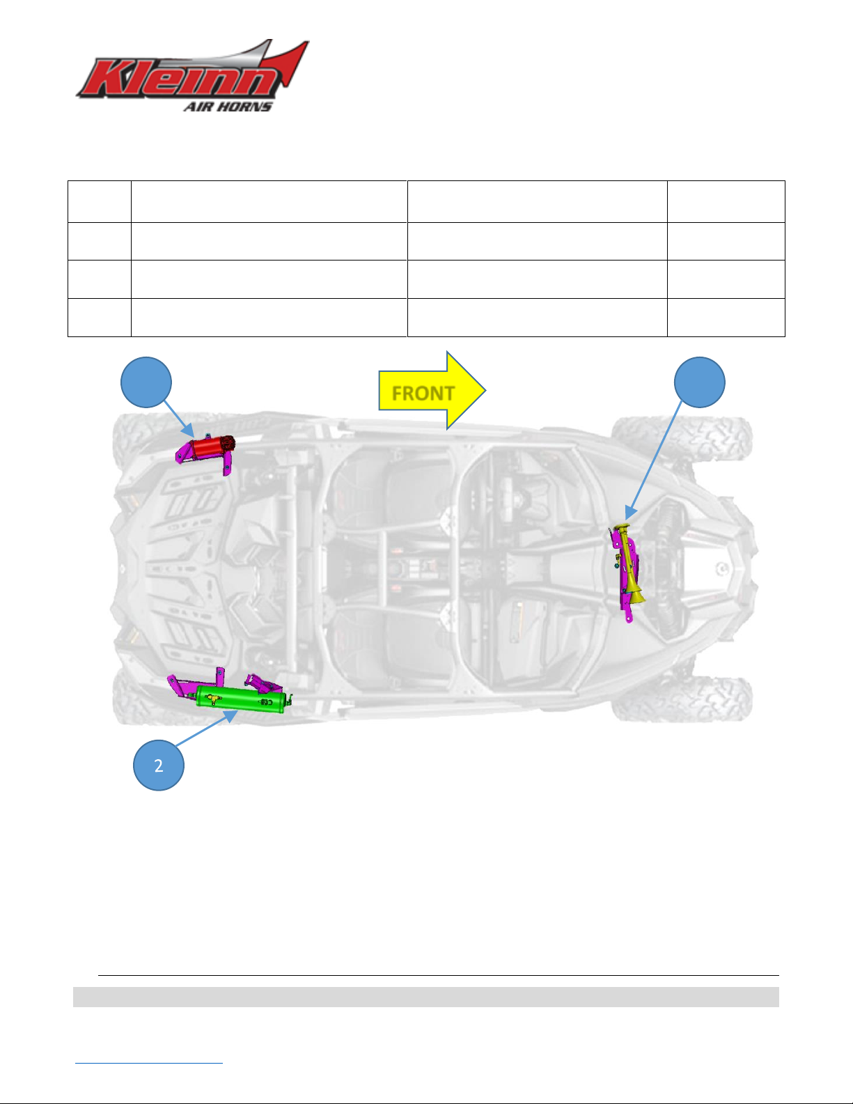
Figure 1 –Top View Showing Kit Layout (2018 X3 2 Door Shown) ......................................................................... 10
Figure 2 –Passenger Rear Fender Removal (fasteners on top of fender) .............................................................. 19
Figure 3 –Passenger Rear Fender Removal (fasteners behind door and fender) .................................................. 19
Figure 4 –Passenger Rear Fender Removal (below tail light)................................................................................. 20
Figure 5 –Passenger Rear Fender Removal (fender resting on tire); Air Tank shown installed............................. 20
Figure 6 –Air Tank Bracket Mounting Locations (side view) .................................................................................. 21
Figure 7 –Air Tank Bracket Mounting Locations (top view) ................................................................................... 21
Figure 8 –Front Air Tank Bracket stops at corner Gusset (Shown with Air Tank) .................................................. 22
Figure 9 –Installing Front Air Tank Brackets, Exploded View ................................................................................. 22
Figure 10 –Installing Rear Air Tank Bracket, Exploded View.................................................................................. 23
Figure 11 –Installing Rear Air Tank Bracket, Proper Bolt Orientation (partial bracket shown) ............................. 23
Figure 12 –Air Tank Fittings installed on Air Tank, Exploded View ........................................................................ 24
Figure 13 –Air Tank Fittings Orientation (from above vehicle) .............................................................................. 24
Figure 14 –Installing Air Tank onto Brackets, Exploded View ................................................................................ 25
Figure 15 –Air Compressor Leader Hose Support Bracket installed (example zip tie routing shown) .................. 26
Figure 16 - Air Compressor with Bolts and X3-102 (Shown with Air Filter and no Leader Hose) ........................... 27
Figure 17 - Air Compressor Bracket with Rubber Grommets Installed................................................................... 28
Figure 18 –Air Compressor Bracket Mounting Locations (side view w/o fender –CARB Version shown)............ 29
Figure 19 –Air Compressor Bracket Mounting Locations (top view)...................................................................... 29
Figure 20 –Installing Air Compressor Bracket, Exploded View............................................................................... 30
Figure 21 –Air Compressor positioned temporarily in place (Shown installed on CARB Vehicle) ......................... 30
Figure 22 –Air Compressor Clearance Adjustment (Shown installed on CARB Vehicle)........................................ 31
Figure 23 –Air Compressor Bracket final installed (Shown installed on CARB Vehicle)......................................... 31
Figure 24 –Air Tubing Route from Air Compressor to Air Tank.............................................................................. 32
Figure 25 –Installing Air Compressor onto Bracket; Exploded View (shown without Leader Hose) ..................... 33
Figure 26 –Air Compressor Filter Remote Tubing shown attached (example vehicle).......................................... 33
Figure 27 –Disassembly of Air Horn by Separating Trumpets................................................................................ 34
Figure 28 –Carriage Bolts temporarily taped in place on Horn Bracket................................................................. 34
Figure 29 –X3-302 with Rubber U-Trim installed, exploded view.......................................................................... 34
Figure 30 –Sway Bar Bolts to remove and Brake Line Bolt (looking from above).................................................. 35
Figure 31 –Air Horn Bracket Installed below Brake Lines....................................................................................... 35
Figure 32 –Installing Trumpet Support Clamp and Trumpets, Exploded View ...................................................... 36
Figure 33 –Installing Air Horn Driver with Tubing attached, Exploded View ......................................................... 37
Figure 34 –Final tightening of Air Horn Brackets and Air Horn .............................................................................. 37
Figure 35 –Final installation of 102 Air Horn (X3 Turbo R shown) ......................................................................... 38
Figure 36 –Example of Air Coupler Mounted to Bumper....................................................................................... 38
Figure 37 –Suggested Ignition Relay Diagram for Air Horn System ....................................................................... 39
Figure 38 –Suggested Wire Routing for Horn, Air Compressor, and Pressure Switch ........................................... 40
Figure 39 –Relay and Fuse location example behind Passenger seat (2019 X3 Turbo RC Shown) ........................ 40
Figure 40 –Recommended install location for Air Horn Button............................................................................. 41