KNOVA KN GEN-30 User manual

KN GEN-30 (3,000 W)
KN GEN-65 (6,500 W)
KN GEN-80 (8,000 W)
Portable generators
Generadores portátiles
We invite you to read
the user manual before
operating your equipment.
Lo invitamos a leer el manual
del usuario antes de operar
su equipo.

Index .................................................................................. 1
Foreward ........................................................................... 1
Safety precautions ............................................................ 1
Safety regulations.............................................................. 1
Glossaries .......................................................................... 3
Parameters ........................................................................ 4
Description of spare parts ................................................. 4
Operation method ............................................................. 6
Transporting ....................................................................... 8
Accessories installation ..................................................... 8
Powers of common appliances ......................................... 9
Maintenance ...................................................................... 10
Electrical schematic diagram ............................................. 13
FOREWARD
INDEX
SAFETY PRECAUTIONS
Thank you for purchasing a generator. This air cooling device, powered by gasoline engine, is a household generator of
compact structure and high performance. lt is applicable to the situation of no electricity supply or sudden electricity cut.
We recommend that the operator read this manual carefully before use this generator, and fully comprehend all requirements
and operating procedure concerning the generator. In case of any questions about this manual, contact the recent authorized
dealer for startup, operation, maintenance program and so on. The technician will teach you how to use the generator in a
correct and safe manner. We also recommend that the operator consult startup and operating procedure of this generator
when buying it.
This generator will work in a safe, effective and reliable way only when it is kept, operated and maintained properly.
Before operation or maintenance of the generator, the operator should:
lt is impossible for manufacturers to predict all hazardous circumstances that may occur, for this reason, warnings in this
manual and caution signs on the generator set may not cover all hazardous circumstances. lf we do not give extra cautions for
operating procedures, methods or techniques, operate the generator in such ways that helps guarantee personal safety, make
sure no damage to generator set arises there from.
To make sure safe operation,Please read carefully three vital safety warnings in this manual and on the generator, preceded
by a safety alert symbol & including:
• Know well and strictly observe local laws and regulations.
• Read and observe all safety warnings in this manual and on the device.
• Let your family get familiar with all safety warnings in this manual.
1
DANGER You WILL be KILLED or SERIOUSLY
HURT if you don’t follow instructions.
WARNING You WILL be KILLED or SERIOUSLY
HURT if you don’t follow instructions.
CAUTION You CAN be HURT if you don’t follow
instructions.
Your generator or other property could be
damaged if you don’t follow instructions.
NOTICE
SAFETY REGULATIONS
DANGER
Do not use it indoors.
DANGER
Keep the machine clean
and avoid spilt combustibles
including gasoline on it.
Do not use it
in a wet conditio
WARNING
Do not connect to
a home power system.
WARNING

2
SAFETY REGULATIONS
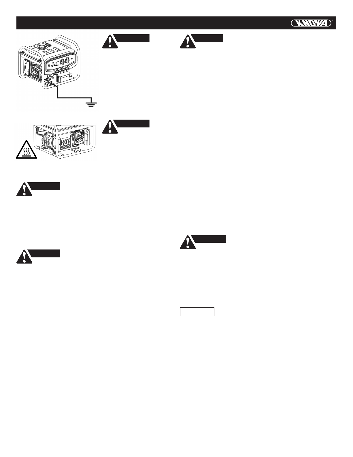
lt must realize safe
grounding.
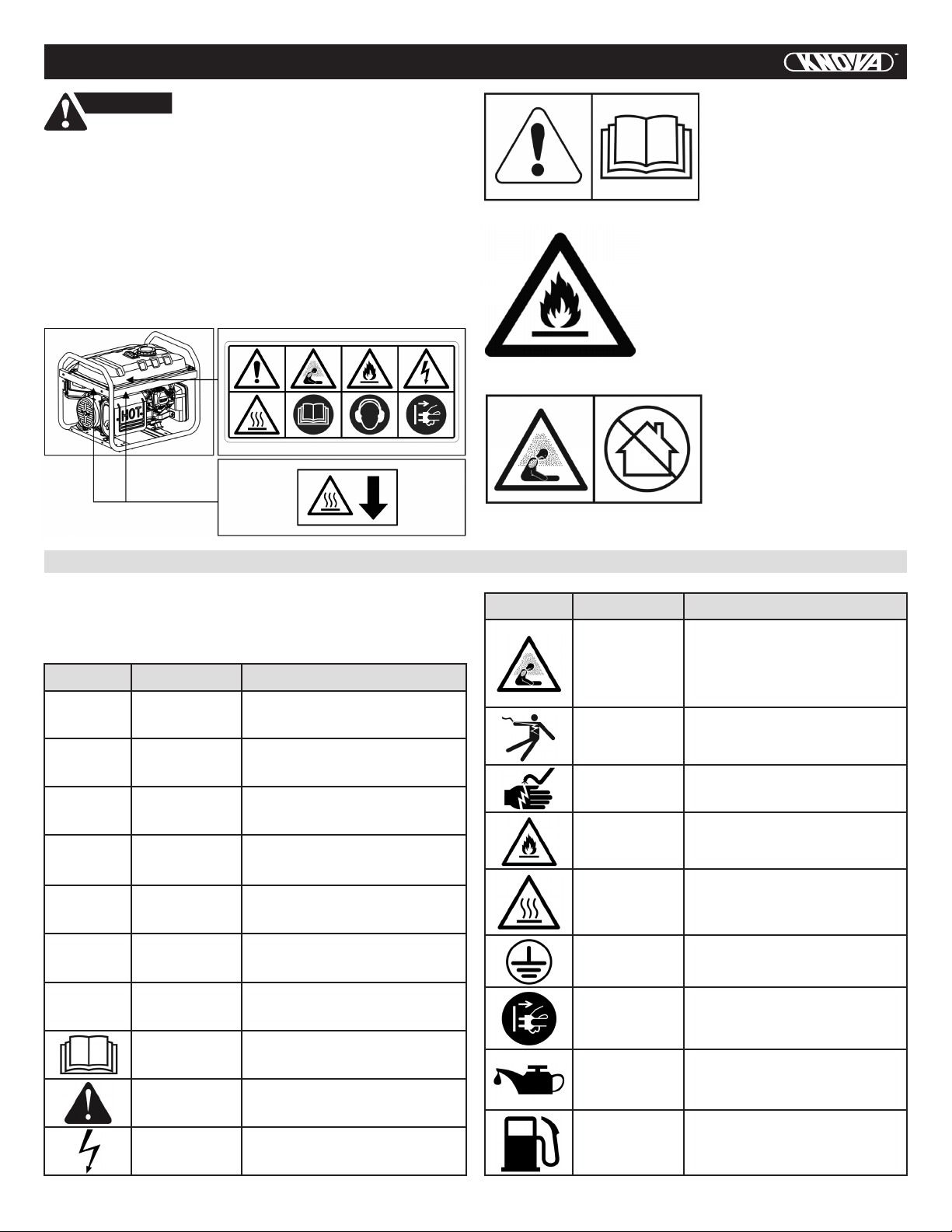
The generator surface has
high temperature, avoid
scalding. Pay attention
to the warnings on
the generating set.
WARNING
WARNING
DANGER
DANGER
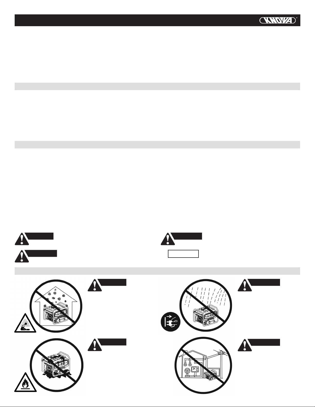
General safety information
The generator produces enough electric power to
cause a serious shock or electrocution if misused.
• Operator should put on personal protective
equipment during operation and maintenance.
• The installation and major repair work shall be carried
out only by specically trained personnel.
• Do not use the generator underground.
• Do not use the generator under an explosive condition.
• lt is prohibited to use bare wire to connect power supply
to the electric equipment directly, use the plug that ts
local regulations.
• In equipment operation, do not touch wire or live parts
of the equipment. Never touch the machine with wet
hands or electrical shock will occur.
• In equipment operation, keep children certain safe
distance from the generator.
• In equipment operation, strictly prohibit assembling
and disassembling any parts.
• lt is suggested to realize tandem connection of a ground
fault circuit interrupter (GFCI) when the power supply is
out to guarantee safety.
• Externa! electric accessory (including cable and plug
interconnecting piece) shall have no fault. Electric shock
defend depends on the breaker, especially the matching
between breaker and generator. During replacement of
the breaker, only that with the same rating and
performance features can be adopted. Contact local
dealers or the after-sales service center for support.
• In case of using lengthening wire or mobile power
distribution cabinet, overall length of the wire with cross
section of 1.5mm2shall be no longer than 60 m, and that
of 2.5mm2shall be no longer than 100 m.
• Avoid connecting the generator in parallel with any
other generator.
DANGER
Fuel of the machine is ammable, which will
generate high temperature and easily cause re
during operation.
• lt is strictly prohibited to add fuel during equipment
operation.
• In case of adding fuel, keep far away from tire brand,
no smoking.
• In case of adding fuel, do not spill fuel on the equipment.
• As to accidental spilling, use cotton cloth to clean it. Start
the equipment after spilt fuel evaporates completely.
• In operation, make sure that there is no ammable
substance within 2 meter range, and no ammable
substance will approach the equipment. Avoid placing any
ammable materials near the exhaust outlet during
operation.
• In case of long-term nonuse, take out the fuel from fuel
tank and store it safely.
• lf you swallow any fuel, inhale fuel vapor, or allow any to
get in your eyes, see your doctor immediately. lf any fuel
spills on your skin or clothing, immediately wash with
soap and water and change your clothes.
• When operating or transporting the machine, be sure it
is kept upright. lf it tilts, fuel may leak from the
carburetor or fuel tank.
• Do not throw the residue fuel and used motor oil into the
trash or pour it onto the ground. We suggest you take
used oil in a sealed container to your local recycling
center or service station for reclamation.
This equipment contains high speed revolving parts,
which will harm human body.
CAUTION
• In equipment operation, do not approach it and strictly
prohibit touching revolving parts.
• In equipment operation, do not lift or move it. Move it
only after equipment completely stopped.
• In equipment operation, observe surroundings. Make
sure no articles are involved into the equipment.
• Do not place heavy weight on the equipment.
• The wheel is for easy moving of the equipment. Do not
use it for long distance moving, otherwise it will be
damaged.
• Do not exceed rated power of the equipment in
operation; otherwise, its service life will be shortened.
Power of common household appliances is shown on
Page 9, 10 in details.
• Please maintain the equipment according to the
requirements so as to prolong its service life. Refer to
Page 10 for details.
• Prevent duct from entering into the equipment during
operation or storage.
NOTICE Operating requirements

3
SAFETY REGULATIONS
WARNING
• A warning reminding the user that he shall conform to
regulations of electrical safety applicable to the place
where the generating sets are used.
• A warning on the requirements and the precautions to be
respected by the user in the case of re-supply by
generating sets of an installation, depending on existing
protective measures in this installation and applicable
regulations.
There is the warning label on the machine to remind you
of the safety regulations.
Read the safety instructions
before using the generator.
Gases such as carbon
monoxide (colorless and
odorless gas) are
produced during operation
which may lead to
suffocation. Only use the
generator in well-ventilated
areas.
Only ll the generator in well-ventilated a reas
and keep it away from open ames, sparks
and cigarettes. Spilled fuel should be
soaked up immediately.
Switch off the engine and let it cool
down before lling the generator. Fuel
is easily ammable and may even
explode under certain circumstances.
GLOSSARIES
Following symbols are quoted on the machine or in this
manual. Please understand their meaning, which will make
your operation easier and safer.
Glossaries
Symbol Name Meaning
V
A
Hz
W
RPM
PF
G1
Volt
Ampere
Hertz
Watt
Power factor
Electric risk
Revolutions
per minutes
Performance
rate
Read
instructions
Safety
warning
Voltage
Current
Frequency (1Hz=60 r/min)
Power
Engine speed
Load transfer efciency
Generator output power
performance rate meat
ISO8528G1
Please read instructions
carefully before use
Can be hurt if not
follow instructions
Indication of electried body.
Pay attention to safety
Symbol Name Meaning
Exhaust from the equipment
contains CO, which is invisible
and in odorous. Excessive
suction of CO may make human
lose consciousness and lead to
death in serious situation.
Toxic gas
Electric shock
Fire
Scalding
No raning
Engine oil
Fuel
This is electric device. You may
suffer electric shock if you
don’t follow the instructions.
The device is electriferous.
No touching during operation.
Fuel and high temperature
generated during operation may
cause re. Operate it cautiously.
Do not use the plug or
electric device in the rain
or make them get wet.
Symbol of adding the engine
oil and the specication is
specied on Page 6.
Symbol of adding the fuel,
which must be gasoline.
Make the machine realize
safe grounding before use
Some parts of equipment will
generate high
temperature during operation,
which will scald skin.
Electriferous,
no touching
Grounding
symbol

(15)
(16)
(17)
(18)
(19)
(21)
(20)
(1)
(2)
(3)
(4)
(5) (6)
(7)
(14)
(13)
(12)
(11)
(10)
(9)
(8)
4
PARAMETERS
Parameters
Model
Frequency
Voltage
Rated power (kW) u
Max. power (kW) l
KN GEN-30 KN GEN-65 KN GEN-80
AC output
Engine
50 /60Hz (subject to the parameter label on the equipment)
Single cylinder, forced air cooling, 4 strokes
Gasoline
F7TC / F7RTC ( N9YC / RN9YC )
0.7 mm
0.10 / 0.15 mm
0.10/ 0.15 mm
T.C.I.
Recoil start / Electric start
2.3 / 2.5 ª
2.5 / 2.8 ª
5.0
5.5
6.0 / 6.5 ª
6.5 / 7.0 ª
110/115V /120/220V /230V/240V
(subject to the parameter label on the equipment)
3,000(50Hz) / 3,600(60Hz)
(subject to the parameter label on the equipment)
Specication
Rpm
Fuel
Engine oil capacity
Spark plug type
Spark plug clearance
Igniting mode
Starting mode
Displacement
Net weight
Uncertainty
L x W x H (mm)
Capacity of fuel tank
Valve clearance (inlet/outlet)
0.6 L
196 cc 389 cc 420 cc
1.1 L 1.1 L
Weight (only for reference)
Overall dimensions (excluding packing box)
46 / 48 kg ¬
15 L 25 L 25 L
590 x 475 x 462 681 x 546 x 550 681 x 546 x 550
79 / 81 kg ¬83 / 85 kg ¬
Noise (according to European Directive 2000/14/EC with amendment 2005/88/EC)
Measured sound pressure level
Measured sound power level
Guaranteed sound power level
74 dB (A) 75 dB (A) 75 dB (A)
94 dB (A) 95 dB (A) 95 dB (A)
2 dB (A) 2 dB (A) 2 dB (A)
96 dB (A) 97 dB (A) 97 dB (A)
DESCRIPTION OF SPARE PARTS
u For continuous
operation,do not exceed
the rated power.
l Limit operation
requiring maximum
power to 30 minutes.
ª 2.8/3.0 means: 2.8kW
with 50Hz, 3.0kW with
60Hz.
¬ 37/39kg means: The net
weight is 37Kg
for recoil start.
The net weight is 39Kg
for electric start.

5
DESCRIPTION OF SPARE PARTS
Fuel tank
Fuel tank cap
AC circuit
breaker
Fuel gauge
AC output
It is used to hold fuel, gasoline is allowed
only.
Screw the fuel injection port in use and do
not open it in equipment operation.
It will break to protect the electric device
when current is too heavy.
It is to indicate fuel level in the fuel tank.
AC output socket provides the power
supply.,Please refer to model’s parameter
table for its rated power. load of each
socket cannot exceed its rated current,
and total power of electric device cannot
surpass rated power of the generator Do
not start up several electric devices
simultaneously, but switch on another
one after stable operation of one electric
device.
(1) Fuel gauge
(2) Chock valve
(3) Fuel valve lever
(4) Starter Grip
(9) Oil drain bolt
(10) Oil lter cap
(11) Battery (optional)
(12) AC output
(13) Output indicator
(14) Panel seat
(15) Fuel tank cap
(16) Fuel tank
(17) Cover, generator end
(18) Mufer
(19) Cylinder head
(20) Carburetor
(21) Spark plug
(5) Air cleaner
(6) Engine switch
(7) DC output
(8) Ground terminal
Output
indicator
DC output
Engine switch
It is to indicate power supply status.
The indicate will brighten up when
the equipment operation.
The output DC is 12V with maximum of
8.3A. It is only used for automotive battery
charging with rated 12V. Pay attention to
connecting the positive and negative
electrode correctly.
It is to start up (applicable to electrical
starting only) and switch off engine.
Turn to the off state in nonuse.
Wheel
(optional)
It is for moving the generator in a short
time.
Battery
(optional)
It is for starting up the generator. In case
of nonuse for three months, charge it.
Oil ller cap
Oil drain bolt
Foot
It is for measurement of engine’s oil level.
Make sure engine’s oil level is between
MIN and MAX in the dipstick of oil ller
cap before use. Oil can be added after
removing the oil ller cap.
Unscrew this bolt when replacing the
engine oil. Drain out the old engine oil and
dispose of it properly according to local
laws, avoiding damage to the environment.
It is to support the generator.
Air cleaner
Fuel switch
Choke valve
Mufer
It is to lter air and remove impurities
in the air entering cylinder. As to the
maintenance method, refer to page 10.
It is to control fuel’s entering into the
engine via fuel tank During nonuse of
generator, leave the switch off.
It is to control air ow into the cylinder
when starting up the engine. As to the
operating method, refer to the page 7.
It is to eliminate noise during equipment
operation, and discharge high temperature
exhaust of engine’s combustion. Do not
touch it to avoid scalding.
Sockets can be following patterns according to relevant
regulations in various areas:
When the rated current from one socket output more
than the socket‘s nominal rated current, you should
to use simultaneously two or more sockets for power
output.
WARNING
Grounding
terminal
It is to make the generator realize safe
grounding. As to the grounding method,
refer to the page 6. Make sure
unobstructed grounding before use.
Handrail pipe After lifted up, the pipe, with self-locking
structure, can be used to move
the generator.
Starter grip It is to start up the engine.
For the method, refer to the page 7.

6
OPERATION METHOD
READ MANUAL
BEFORE
OPERATING
GENERATOR!
START
START
ON
WAIT
5 SEC.
SHUT DOWN
OFF
WAIT
30 SEC.
OFF
Shift the machina outdoors, use wire of no less than 2.5 mm2
to make the machina and grounding terminal connected to
the ground. One end of the wire is pressed below the
buttery nut of the unit, screwed up tightly, and the other
end is connected with the metal rod shape article (such as
the iron nail and the opener), and inserted into soil.
• Unit grounding
• Starting the generator set
Filling oil
START
Upper level
Remove the oil ller cap, ll oil of proper model. As to
dosage, refer to Page 4. Use the funnel far lling, in case of
careless spilling, clean the ground to avoid slipping.
Oil specication table
SAE
TEMP
AMBIENT TEMPERATURE
Filling fuel
No exceeding
this level
Open the fuel tank cap and ll gasoline, the fuel leveler’s
position will display gasoline mass in the fuel tank and take
care the maximum fuel position shall not exceed the inner
strainer of the tank when lling.
Keep away from the re source and heat
source when lling; do not ll gasoline when be operating.
WARNING
Connect electric battery (electric start only)
Connect the storage battery wire
to the storage battery, red for
positive electrode and green for the
negative electrode, and make sure
screwing the nut tightly. Not contact
between positive electrode to nega-
tive electrode to avoid short circuit.
After connection, metal parts of
two pieces of wire shall keep at
least 15 mm safety distance, and be
protected by rubber cover.
Turn on the fuel valve lever
Turn the fuel valve lever to ON
and let the fuel ow into the
carburetor.
ON

OPERATION METHOD
7
Close the choke valve
When the unit is in cold state,
move the choke valve to the full
closed position, and half closed
position in thermal state. If the
generator unit is not started for
two times in succession, move
the choke valve to the open
position and then to operate
the switch or hand-pull starter.
Start the generator
Turn the engine switch on the
control panel to ON. Or press it
to START if it’s electrical start
state, then generator unit can
be started. In order to extend
the service life of the storage
battery, do not press on the
switch for more than 3 seconds
and the interval between two
pressing should be longer than
10 seconds.
START
Start the generator recoil start
Start via the pull wire: Pull the
wire gently to connect the disc
to the starting bowl inside the
unit. Pull the wire out in an
instant action and the generator
unit will be started after doing
this twice. If it is not started,
please conduct the above
operation with the choke valve.
It may be causing the dangers of injury
by the sudden change of rotation direction of the
engine during operating the recoil starter.
WARNING
Open the choke valve
After starting, let the unit run
without load for 5 seconds and
then turn on the choke valve
switch.
WAIT
5 sec
Connect to load
Access electric equipment and
turn the circuit breaker to ON.
Please note that when several
loads are used at the same time,
do not access the next one uniess
the former one is running normally.
The total power of the loads
should not exceed the rated
power of the unit.
Connect to load
Disconnect the electric
equipment from the control
panel of the generator.
• Shut down the engine
SHUT DOWN
Turn off the engine switch
After 30 seconds of no-load
running, turn off the engine
switch and the generator unit
will be shut down immediately.
OFF
WAIT
30 sec
Close the fuel valve lever
Turn off fuel valve lever after
the shutdown of the unit.
OFF
The surface
temperature of the
generator unit is still high after
shutdown, and it can not be
moved or operated before cooling
down in order to avoid scalding
.
WARNING
Drain the fuel
Protective treatment
Remove the oil draining bolt
of the carburetor and drain
the fuel from the fuel tank and
carburetor. Then tighten the
oil draining bolt again (if the
fuel is not drained, the fuel will
evaporate and ow into the air,
and the residues may block the
carburetor).
The unit should be stored in
a clean and dry place and
should be protected from rain
and high temperature. Shield
the unit with paper box or
plastic bag to prevent dust
from entering the unit.
• Storage

TRANSPORTING
8
• Transporting
To prevent fuel spillage when transporting or during temporary
storage, the generator should be secured upright in its
normal operating position, with the engine switch OFF
The fuel valve lever should be turned OFF.
When transporting the generator:
WARNING
• Do not overll the tank
• Do not operate the generator while it is on a vehicle.
Take the generator off the vehicle and use it in a well
ventilated place.
• Avoid a place exposed to direct sunlight when putting
the generator on a vehicle. If the generator is left in an
enclosed vehicle for many hours, high temperature inside
the vehicle could cause fuel to vaporize resulting in
a possible explosion.
• Do not drive on a rough road for an extended period with
the generator on board. If you must transport the
generator on a rough road, drain the fuel from the
generator beforehand.
NOTE: To transport the generator, hold the holding part
(shaded areas in the gure 1).
Take care not to drop or strike the generator when
transporting.
Do not place heavy objects on the generator.
When transporting the generator by loading it on to a
vehicle, secure to the generator frame as shown
(see gure 2).
Holding part
gure 1
gure 2
ACCESSORIES INSTALLATION
• Accessories installation • Two-wheel short axie (applicable to generator units
of KN GEN-30, KN GEN-65, KN GEN-80)
You can install the wheel assemblies for the convenience of
moving the unit.
You may need to prepare the following equipment before the
installation.
According to the different model congurations, there are
several kinds of wheels. Please install the handrail, vibration
reduction bracket and wheel on the base plate and tighten
the bolt as shown in the following picture.
Axle
Wheel
Handrail
Vibration reduction
bracket
Vibration reduction rubber pad
Cotter
pin
Washer

9
ACCESSORIES INSTALLATION
• Two-wheel long axie (applicable to generator units
of KN GEN-30)
Axle
Wheel
Handrail
Vibration
reduction
bracket
Vibration reduction
rubber pad
Cotter
pin
Washer
Axle clamp
• Four-wheel long axie (applicable to generator units
of KN GEN-65, KN GEN-80)
Long axle
Brake
dise
Short axle
Axle clamp
Wheel
Washer
Cotter
pin
Some of the units, which are of the electrical starting type,
need to be equipped with external storage battery bracket.
Please conduct the installation according to the following
drawing.
Storage
battery Storage
battery
clamp Storage
battery
shield
Storage
battery
shield
Storage
battery
bracket
Bracket
connection tube
Negative
terminal
Positive
terminal
Starte cable
(positive)
Starte
solenoid
Operating steps and installation instructions:
1 Install the positive terminal and negative terminal onto
the generation unit as specied in the drawing.
2 Install the storage battery bracket onto the bracket
connection tube.
3 Install the storage battery shield onto the bracket
connection tube.
4 Install the assembled bracket onto the unit.
5 Put the storage battery into the bracket.
6 Hook the hook bolt to the hole of the bracket,
and install it onto the storage battery clamp.
7 Tighten the bolt and install the storage battery
onto the bracket.
8 Connect the storage battery wires and connect
the negative one rst. The connected terminals may
be different as the models of the storage batteries
are different. Take material object as.
9 Some storage batteries need to be lled with electrolyte
before installation. Please read the specication of
the storage battery carefully.
POWERS OF COMMON APPLIANCES
Electric equipment Rated
power (W)
Starting
power (W)
Flat panel
television
27”
120
1000
1000
5 ~ 50
5 ~ 50
120
Household appliances
Energy
saving
lamp
Electric
cooker
Electric equipment Rated
power (W)
Starting
power (W)
Computer
400
50
300
100
100
400
Household appliances
DVD
Refrigerator

POWERS OF COMMON APPLIANCES
10
Electric equipment Rated
power (W)
Starting
power (W)
Washing
machine
250
1600
3200
50
100
500
Household appliances
Electric
fan
Air
condition
2HP
Electric equipment Rated
power (W)
Starting
power (W)
Electric
welder
2500
800
1200
1000
1500
5000
Tools
Electric
hammer
Water
pump
The starting powers of the appliances are far more higher than the operation powers. Please read the labels of the electric
equipment for reference. The total power of the loads should not exceed the rated power of the generator.
Maintenance
Good maintenance is the best guarantee of safe, economical
and fault-free operation. And it also contributes
to environmental protection.
Maintenance schedule is as follows:
MAINTENANCE
Engine
oil
Inspect
the oil level
Schedule for
regular
maintenance
Per use
Every 20 hours
or in the first
month of initial
use (3)
Every 50 hours
or every 3
months (3)
Every 100
hours or every
6 months (3)
Every 300
hours or every
year (3)
Replace
Inspect
Clean
Clean
Replace
Clean
Wash
Wash
Replace
Readjust
Spark
plug
Valve
clearance
Cylinder
head
Fuel tank
and
strainer
Air
cleaner
Fuel
switch
sediment
cup
Fuel tube
(1)
(2)
Every 300 hours (2)
Every 2 years (2)
Every 2 years (2)
(1) Maintenance should be conducted frequently if the unit is
used in dusty places.
(2) Maintenance should be conducted by the franchised
dealer.
(3) When the unit is used frequently, please conduct the
maintenance according to the above mentioned intervals
so as to ensure the long-term usage of the generator.
• Replace the engine oil
Oil lter
cap Oil drain
bolt
Upper
level
Remove the oil draining bolt and drain the long time stored
oil. Tighten the oil draining bolt and twist off the oil dipstick.
Fill in appropriate amount of oil via the oil dipstick and keep
the oil lever between MIN and Max.
• Clean the air cleaner
Clip
Air cleaner
cover
Air cleaner
element Element
1 Remove the clip of the air cleaner cover and open it.
2 Inspect the cleaner element and ensure that it is sound
and clean.
3 If the foam cleaner element is dirty, spray some household
cleaning agent onto the cleaner element. Scrub it for
several minutes and rinse it with warm water. If the
cleaner element is damaged, please replace a new one.

11
MAINTENANCE
• Clean the fuel valve lever sediment cup
Fuel valve
Sediment
cup
Fuel
lter
O-ring
Sediment
cup
1. Close the fuel valve and remove the sediment bowl.
Take out the O-type seal ring and strainer.
2. Clean the sediment bowl, O-type seal ring and strainer
with incombustible or high-ash solvent.
3. Reinstall the O-type seal ring and strainer, and tighten
the sediment bowl.
4. Open the fuel valve and inspect for leakage.
• Valve clearance
(should be conducted by a professional person)
Feeler
gauge
Remove the cylinder head cover and measure the valve
clearance with the feeler gauge. The clearances are 0.1 mm
for the inlet valve and 0.15 mm for the outlet valve.
10,000-DC, 10,000D-DC: The clearances are 0.07 mm for
the inlet valve and 0.10 mm for the outlet valve.
• Clean the spark plug
Recommended spark plug models F7RTC and F7TC
Spark plug
wrench
Spark plug
cap
0.70-0.80 mm
1. Remove the spark plug cap.
2. Clean the spark plug base.
3. Remove the spark plug with the spark plug socket spanner.
4. Open Inspect the spark plug insulator visually for
damage. If it is damaged, replace a new one.
5. Measure the spark plug gap with a fap gauge.
Twist the side electrode to adjust the gap.
The gap should be kept between 0.70 and 0.80 mm.
6. Inspect if the washer of the spark plug
is in good condition.
7. Reinstall the spark plug and tighten it with the spark plug
socket spanner. Press down the washer of the spark plug
and place the spark plug cap.

Fault phenomenon Fault cause Operation method
No fuel Fill the oil tank with gasoline
The oil switch is not turned on Turn the oil switch to ON
Clean the oil cup (refer to page 11)The oil switch is blocked
No engine oil or the engine oil level is low
Clean or replace the spark plug
(refer to page 11)
Move the choke to the “on”
position during operation
Let the engine run at empty
load for more than 10 min.
Turn the circuit breaker
to the “on” position
The shutdown switch is turned off
The circuit breaker is not connected
The plug is poorly contacted
The choke position is incorrect
Clean the lter element to the air lter
Choose appropriate engine oil type
(refer to page 6)
Clear or replace the spark plug
(refer to page 11)
Adjust the valve clearance
(refer to page 11)
The fuel oil is contaminated
Reduce load to the rated limit
The air lter is dirty
The load is too high
The engine oil is too much
The engine oil type is incorrect
The valve clearance is out of limits
The spark plug fails
The temperature of
the engine is too low
Turn the switch to the “on” position
The spark plug fails
Replace clean oil
Drain some oil
Replace a socket
Add oil
The generator
can not start
No power
output
Vibration while
operation
The generator emits black smoke
The generator emits blue smoke
The power
decreases
Vibration while
operation
Common fault analysis
• The environmental requirements of the generator:
• Suitable temperature: -15º C -40º C.
• Suitable humidity: lower than 95%
• Suitable altitude: under 1,000 meters (it should be used with lower power in districts higher than 1,000 meters).
• The generator set can only be loaded to the rated power under the specied environment conditions. If the environment
conditions are inconsistent with the above standards, or if the cooling conditions of the engine and generator set are
defective; for example, when running in limited areas, it is necessary to reduce the power. It is also necessary to reduce
the power when the temperature, altitude and relative humidity exceed the standards.
• If there is no problem with the conditions above, please turn to the nearby dealer or after-sales service center
for consultants.
MAINTENANCE
12

ELECTRICAL SCHEMATIC DIAGRAM
13
• Electrical schematic diagram 1
110V/220V, 115V/230V, 120V/240V (applicable to KN GEN-30)
Control panel block
AC output
230V 16A
AC output
115V 16A
Voltage
selector
V-lamp
Circuit
brecker 10A
Ground
terminal
Engine S.W.
DC
terminal
DC 12V
DC protector
10A
Main
winding
DC diode
DC
winding
Exciter
winding
Field
winding
Generator block
White
Green
Red
Blue Black
Yellow
Grey
Brown
Colour comb Combination
switch
Oil level
switch Oil
alert
Spark
plug Ignition
coil
Engine block

14
ELECTRICAL SCHEMATIC DIAGRAM
• Electrical schematic diagram 2
110V/220V, 115V/230V, 120V/240V (applicable to KN GEN-65)
Control panel block
Ground
terminal
AC output
220V 32A
AC output
110V 32A
AC output
110V 32A
Circuit
brecker 22A
V-lamp
Main
winding
DC
winding
DC
protector
10A
DC diode
DC
terminal
DC 12V Engine S.W.
Engine block
Engine block
Oil level
switch
Oil
alert
Spark
plug
Ignition
coil
Fuel cut
solenoid
Engine S.W.
Colour comb
White
Grey
Red
Blue
Orange
Yellow / Green
Brown
Grey
Black
Yellow
Exciter
winding
Field
winding
Generator block

ELECTRICAL SCHEMATIC DIAGRAM
• Electrical schematic diagram 3
110V/220V, 115V/230V, 120V/240V (applicable to KN GEN-80)
AC output
220V 32A
AC output
110V 32A
AC output
110V 32A
Control panel block
Ground
terminal
Engine S.W.
V-lamp
DC protector 10A
DC diode
DC
terminal
DC 12V
Circuit
brecker 22A
Fuse 5A
Main
winding
DC
winding
Exciter
winding
Field
winding
Generator block
Fuel cut
winding
Fuse 5A
A V R
Engine block
Oil level
switch
Charge
coli
Fuel cut
solenoid Oil
alart Spark
plug Ignition
coil
Starter
Battery
Combination swich
Colour comb
White
Grey
Red
Blue
Orange
Brown
Grey
Black
Yellow
Yellow / Green
15

INDICE
16
Indice ................................................................................. 16
Introducción ....................................................................... 16
Precauciones de seguridad ................................................ 16
Regulaciones de seguridad ................................................ 16
Glosario ............................................................................. 18
Parámetros ........................................................................ 19
Descripción de repuestos .................................................. 19
Método de operación ......................................................... 21
Transportando ................................................................... 23
Instalación de accesorios .................................................. 23
Potencias de aparatos comunes ........................................ 24
Mantenimiento ................................................................... 25
Diagrama esquemático eléctrico ....................................... 28
INTRODUCCIÓN
PRECAUCIONES DE SEGURIDAD
Gracias por comprar un generador. Este dispositivo de refrigeración por aire, accionado por motor de gasolina, es un
generador doméstico de estructura compacta y alto rendimiento. Es aplicable a la situación de falta de suministro eléctrico
o corte repentino del suministro eléctrico.
Recomendamos que el operador lea detenidamente este manual antes de usar este generador y que comprenda
completamente todos los requisitos y procedimientos operativos relacionados con el generador. Si tiene alguna pregunta
sobre este manual, comuníquese con el distribuidor autorizado más reciente para el programa de puesta en marcha, operación,
mantenimiento, etc. El técnico le enseñará a utilizar el generador de forma correcta y segura. También recomendamos que
el operador consulte el procedimiento de puesta en marcha y funcionamiento de este generador al comprarlo.
Este generador funcionará de manera segura, efectiva y conable solo cuando se, opere y mantenga adecuadamente.
Antes de la operación o mantenimiento del generador, el operador debe:
Es imposible para los fabricantes predecir todas las circunstancias peligrosas que pueden ocurrir, por esta razón, las
advertencias en este manual y las señales de precaución en el grupo electrógeno pueden no cubrir todas las circunstancias
peligrosas. Si no brindamos precauciones adicionales para los procedimientos, métodos o técnicas de operación, opere el
generador de tal manera que ayude a garantizar la seguridad personal, asegúrese de que no se produzcan daños al grupo
electrógeno.
Para garantizar un funcionamiento seguro, lea atentamente tres advertencias de seguridad vitales en este manual
y en el generador, precedidas por un símbolo de alerta de seguridad e incluyendo: :
• Conozca bien y observe estrictamente las leyes y reglamentos locales.
• Lea y observe todas las advertencias de seguridad en este manual y en el dispositivo.
• Deje que su familia se familiarice con todas las advertencias de seguridad de este manual.
PELIGRO SERÁ MUERTO o GRAVEMENTE
HERIDO si no sigue las instrucciones.
ADVERTENCIA SERÁS MUERTO o GRAVEMENTE
DAÑO si no sigue las instrucciones.
PRECAUCIÓN PUEDE SER HERIDO si no
sigue las instrucciones.
Su generador u otra propiedad podría
dañarse si no sigue las instrucciones.
NOTICIA
REGULACIONES DE SEGURIDAD
No lo use en interiores.
Mantenga la máquina limpia
y evite derramar
combustibles, incluida
la gasolina, sobre ella.
No lo use en condiciones
húmedas.
No lo conecte a un sistema
de energía doméstico.
PELIGRO
PELIGRO
ADVERTENCIA
ADVERTENCIA

REGULACIONES DE SEGURIDAD
17
Debe realizar
una puesta a tierra segura.
La supercie del
generador tiene alta
temperatura, evite
quemaduras. Preste
atención a las advertencias
en el grupo electrógeno.
Información general de seguridad
El generador produce suciente energía eléctrica
para causar una descarga grave o electrocución si se usa
incorrectamente.
• El operador debe ponerse el equipo de protección
personal durante la operación y el mantenimiento.
• Los trabajos de instalación y reparación mayor deben
ser realizados únicamente por personal especícamente
capacitado.
• No utilice el generador bajo tierra.
• No utilice el generador en condiciones explosivas.
• Está prohibido usar cable pelado para conectar la fuente
de alimentación al equipo eléctrico directamente, use
el enchufe que cumpla con las normas locales.
• Durante el funcionamiento del equipo, no toque los
cables ni las partes vivas del equipo. Nunca toque
la máquina con las manos mojadas o se producirá
una descarga eléctrica.
• Durante la operación del equipo, mantenga a los niños
a cierta distancia segura del generador.
• En la operación del equipo, prohíba estrictamente
el montaje y desmontaje de cualquier pieza.
• Se sugiere realizar la conexión en tándem de un
interruptor de circuito de falla a tierra (GFCI) cuando
la fuente de alimentación está cortada para garantizar
la seguridad.
• Externa! accesorio eléctrico (incluido el cable y la pieza
de interconexión del enchufe) no debe tener fallas. La
protección contra descargas eléctricas depende del
disyuntor, especialmente de la coincidencia entre el
disyuntor y el generador. Durante el reemplazo del
interruptor, solo se puede adoptar uno con las mismas
características nominales y de rendimiento. Póngase en
contacto con los distribuidores locales o el centro de
servicio postventa para obtener asistencia.
• En caso de usar un cable de extensión o un gabinete de
distribución de energía móvil, la longitud total del cable
con una sección transversal de 1.5 mm2no debe ser
mayor a 60 m, y la de 2.5 mm2no debe ser mayor a 100 m.
• Evite conectar el generador en paralelo con cualquier
otro generador.
El combustible de la máquina es inamable, lo que
generará altas temperaturas y provocará incendios
fácilmente durante el funcionamiento.
• Está terminantemente prohibido agregar combustible
durante la operación del equipo.
• En caso de agregar combustible, manténgase alejado de
la marca de neumáticos, no fume.
• En caso de agregar combustible, no derrame
combustible sobre el equipo.
• En caso de derrame accidental, use un paño de algodón
para limpiarlo. Arranque el equipo después de que
el combustible derramado se evapore por completo.
• En funcionamiento, asegúrese de que no haya ninguna
sustancia inamable dentro de un rango de 2 metros y
que ninguna sustancia inamable se acerque al equipo.
Evite colocar cualquier material inamable cerca de
la salida de escape durante el funcionamiento.
• En caso de no uso a largo plazo, saque el combustible del
tanque de combustible y guárdelo de manera segura.
• Si traga combustible, inhala vapor de combustible o le
entra en los ojos, consulte a su médico de inmediato.
Si se derrama combustible sobre la piel o la ropa, lávese
inmediatamente con agua y jabón y cámbiese de ropa.
• Cuando opere o transporte la máquina, asegúrese de
que se mantenga en posición vertical. Si se inclina, es
posible que se escape combustible del carburador o del
tanque de combustible.
• No arroje los residuos de combustible y aceite de motor
usado a la basura ni los vierta en el suelo. Le sugerimos
que lleve el aceite usado en un recipiente sellado a su
centro de reciclaje o estación de servicio local para su
recuperación.
Este equipo contiene piezas giratorias de alta
velocidad que dañarán el cuerpo humano.
• En funcionamiento del equipo, no se acerque y prohíba
estrictamente tocar las piezas giratorias.
• En funcionamiento del equipo, no lo levante ni lo mueva.
Muévalo solo después de que el equipo se haya detenido
por completo.
• Durante la operación del equipo, observe el entorno.
Asegúrese de que no haya artículos involucrados
en el equipo.
• No coloque peso pesado sobre el equipo.
• La rueda es para facilitar el movimiento del equipo.
No lo use para mudanzas de larga distancia,
de lo contrario se dañará.
• No exceder la potencia nominal del equipo en
funcionamiento; de lo contrario, su vida útil se acortará.
La potencia de los electrodomésticos comunes se
muestra en las páginas 24 y 25 en detalle.
• Mantenga el equipo de acuerdo con los requisitos para
prolongar su vida útil. Consulte la página 25 para
obtener más detalles.
• Evite que el conducto entre en el equipo durante
la operación o el almacenamiento.
NOTICIA Requisitos operativos
ADVERTENCIA
ADVERTENCIA
PELIGRO
PELIGRO
PELIGRO
PRECAUCIÓN

REGULACIONES DE SEGURIDAD
18
• Una advertencia recordando al usuario que debe cumplir
con las normas de seguridad eléctrica aplicables al lugar
donde se utilizan los grupos electrógenos.
• Una advertencia sobre los requisitos y las precauciones
que debe respetar el usuario en caso de realimentación
mediante grupos electrógenos de una instalación, en
función de las medidas de protección existentes en dicha
instalación y la normativa aplicable.
Hay una etiqueta de advertencia en la máquina para
recordarle las normas de seguridad.
Lea las instrucciones de
seguridad antes de utilizar
el generador.
Durante el funcionamiento
se producen gases como el
monóxido de carbono (gas
incoloro e inodoro) que
pueden provocar asxia.
Solo use el generador en
áreas bien ventiladas.
Solo llene el generador en áreas bien ventiladas
y manténgalo alejado de llamas abiertas,
chispas y cigarrillos. El combustible
derramado debe limpiarse inmediatamente.
Apague el motor y deje que se enfríe antes
de llenar el generador. El combustible
es fácilmente inamable e incluso
puede explotar en determinadas
circunstancias.
GLOSARIOS
Los siguientes símbolos se citan en la máquina o en este
manual. Por favor, comprenda su signicado, lo que hará
que su operación sea más fácil y segura.
Glosarios
Símbolo Nombre Signicado
V
A
Hz
W
RPM
PF
G1
Voltio
Amperio
Hercios
Vatio
Factor
de potencia
Riesgo
eléctrico
Revoluciones
por minuto
Tasa de
rendimiento
Leer
instrucciones
Advertencia
de seguridad
Voltaje.
Corriente.
Frecuencia (1Hz=60 r/min).
Energía.
Velocidad del motor.
Eciencia de
transferencia de carga.
Tasa de rendimiento de
potencia de salida del generador
ISO8528G1.
Por favor, lea las instrucciones
cuidadosamente antes de usar.
Puede lastimarse
si no sigue las instrucciones.
Indicación de
cuerpo electricado.
Preste atención a la seguridad.
Símbolo Nombre Signicado
Los gases de escape del equipo contienen
CO, que es invisible e inodoro. La
inhalación excesiva de CO puede hacer
que el ser humano pierda el conocimiento y
provocar la muerte en situaciones graves.
Gas
toxico
Descarga
eléctrica
Fuego
Escaldada
Sin lluvia
Aceite
de motor
Gasolina
Este es un dispositivo eléctrico.
Puede sufrir una descarga eléctrica
si no sigue las instrucciones.
El dispositivo es electrífero.
Sin tocar durante el funcionamiento.
El combustible y la alta temperatura
generada durante el funcionamiento pueden
provocar un incendio. Opérelo con cautela.
No utilice el enchufe o el aparato
eléctrico bajo la lluvia ni los moje.
El símbolo de agregar
el aceite de motor se
especican en la página 21.
Símbolo de añadir el combustible,
que debe ser gasolina.
Haga que la máquina realice
una conexión a tierra
segura antes de su uso.
Algunas partes del equipo
generarán altas temperaturas
durante el funcionamiento,
lo que escaldará la piel.
Energizado,
no tocar
Puesta
a tierra
ADVERTENCIA

PARÁMETROS
19
(15)
(16)
(17)
(18)
(19)
(21)
(20)
(1)
(2)
(3)
(4)
(5) (6)
(7)
(14)
(13)
(12)
(11)
(10)
(9)
(8)
Parámetros
Modelo
Frecuencia
Voltaje
Potencia nominal (kW) u
Máxima potencia (kW) l
KN GEN-30 (3,000 W) KN GEN-65 (6,500 W) KN GEN-80 (8,000 W)
Salida de CA
Motor
50 / 60 Hz (sujeto a la etiqueta del parámetro en el equipo)
Monocilíndrico, refrigeración por aire forzado, 4 tiempos
Gasolina
F7TC / F7RTC ( N9YC / RN9YC )
0.7 mm
0.10 / 0.15 mm
0.10/ 0.15 mm
T.C.I.
Comienzo de retroceso / Arranque eléctrico
2.3 / 2.5 ª
2.5 / 2.8 ª
5.0
5.5
6.0 / 6.5 ª
6.5 / 7.0 ª
110/115V / 120/220V / 230V/240V
(sujeto a la etiqueta del parámetro en el equipo)
3,000(50 Hz) / 3,600(60 Hz)
(sujeto a la etiqueta del parámetro en el equipo)
Especicación
RPM
Combustible
Capacidad de aceite del motor
Tipo de bujía
Juego de bujías
Modo de encendido
Modo de inicio
Desplazamiento
Peso neto
Incertidumbre
largo x alto x fondo (mm)
Capacidad del tanque de combustible
Juego de válvulas (entrada/salida)
0.6 L
196 cc 389 cc 420 cc
1.1 L 1.1 L
Peso (solo como referencia)
Dimensiones totales (excluyendo la caja de embalaje)
46 / 48 kg ¬
15 L 25 L 25 L
590 x 475 x 462 681 x 546 x 550 681 x 546 x 550
79 / 81 kg ¬83 / 85 kg ¬
Ruido (según Directiva Europea 2000/14/EC con enmienda 2005/88/EC)
Nivel de presión sonora medido
Nivel de potencia de sonido medido
Nivel de potencia de sonido garantizado
74 dB (A) 75 dB (A) 75 dB (A)
94 dB (A) 95 dB (A) 95 dB (A)
2 dB (A) 2 dB (A) 2 dB (A)
96 dB (A) 97 dB (A) 97 dB (A)
DESCRIPCIÓN DE REPUESTOS
u Para un funcionamiento
continuo, no exceda
la potencia nominal.
l Limite la operación que
requiere potencia máxima
a 30 minutos.
ª 2,8/3,0 signica:
2,8 kW con 50 Hz,
3,0 kW con 60 Hz.
¬ 37/39 kg signica:
El peso neto es de 37 kg
para arranque manual.
El peso neto es de 39 kg
para arranque eléctrico.
This manual suits for next models
2
Table of contents
Languages:
Other KNOVA Portable Generator manuals
Popular Portable Generator manuals by other brands

Cross Tools
Cross Tools TRAVELBOX 500+ Operating instruction

Lincoln Electric
Lincoln Electric SPEEDTEC 400SP Operator's manual

Thunder Scientific
Thunder Scientific 2900 quick start guide

Champion Power Equipment
Champion Power Equipment 41351 Owner's Manual and Operating Instructions

VICI DBS
VICI DBS GT ULTRA ZERO AIR GENERATOR user manual

Briggs & Stratton
Briggs & Stratton 1933 Illustrated parts list