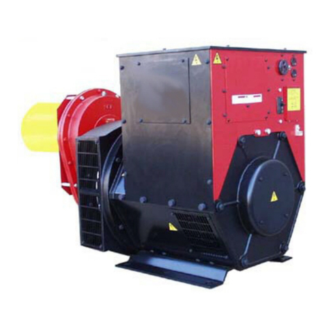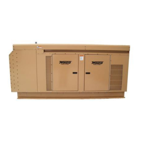
5REV B 60706-199
WARNING: PERSONAL INJURY & EQUIPMENT DAMAGE
Trailer may tip over and cause injuries if wheels are not spaced far
enough apart.
THREE-POINT HITCH KIT
Optional 3-Point Hitch Part Number TPH241
WARNING: PERSONAL INJURY & EQUIPMENT DAMAGE
When using the 3-point hitch assembly all three points must be
attached to the tractor. Failure to do so will cause the generator to tip
when lifting it damaging both the t-bar and the generator.
A. The three point hitch must be attached to the tractor at all times
during operation.
B. When operating the generator the three point hitch and generator
mustbesittingonatlevelground.Allfourdeckpadsmustbein
constant contact with the ground at all times. This will reduce the
vibration in both the generator and the tumbling bar.
C. For safety the generator must be bolted to the three point hitch deck
using all four mounting bolts.
Page 3 60706-180
0310-00
B. The foundation must be solid enough to absorb generator
starting and reflected load torque during operation.
C. The foundation surface should be flat.
D. Space is required around the generator for mounting
switching devices, making connections, and for servicing.
E. The generator mounting bracket must rest evenly and
firmly on the foundation. Install shims if necessary to even
out the foundation under the mounting pads then bolt the
generator firmly in place.
TRAILER MOUNTING
Mount the generator on a trailer if you plan to use it as a
portable power source. When selecting or building a trailer to
mount the generator, consider the following points:
A. The trailer construction must be strong enough to support
the generator.
B. The design of the trailer must enable the trailer to remain
stable during operation, and to resist tipping caused by
generator starting and reflected load torque.
WARNING: Personal Injury & Equipment Damage
TRAILER MAY TIP OVER AND CAUSE INJURIES IF
WHEELS ARE NOT SPACED FAR ENOUGH APART.
Optional Trailer Part Number TDM75
C. The trailer height and mounting position of the generator on
the trailer should enable aligning the drive shaft (tumbling bar)
in a straight or nearly straight line between the power take-off
and generator input shafts. Misalignment must be less than 10
degrees during generator operation, even though the mechani-
cal design of the tumbling bar would allow greater misalign-
ment.
D. The generator mounting area of the trailer bed should be
flat.
All four generator mounting pads must rest firmly on the trailer
bed. Install shims if necessary to even out the bed under the
mounting pads, then bolt the generator firmly in place.
WINCO THREE POINT HITCH
Optional 3-Point Hitch Part Number TPH240
WARNING: Personal Injury & Equipment Damage
WHEN USING THE 3-POINT HITCH ASSEMBLY ALL THREE
POINTS MUST BE ATTACHED TO THE TRACTOR. FAIL-
URE TO DO SO WILL CAUSE THE GENERATOR TO TIP
WHEN LIFTING IT DAMAGING BOTH THE T-BAR AND THE
GENERATOR.
A. The three point hitch must be attached to the tractor at all
times during operation.
B. When operating the generator the three point hitch and
generator must be sitting on flat level ground. All four deck
pads must be in constant contact with the ground at all
times. This will reduce the vibration in both the generator
and the tumbling bar.
C. For safety the generator must be bolted to the three point
hitch deck using all four mounting bolts
ELECTRICAL CONNECTIONS
CAUTION:
Only qualied electricians should install electrical wiring. Wiring must
conform to all applicable national, state, and local codes. (Reference:
National Fire Protection Association Manual No. 70, National Electrical
Code.)
DANGER: PERSONAL INJURY:
If the generator is to be used as a standby power source,, a manual
transfer switch must be installed to separate the generator and the
commercial power lines. The switch must isolate the generator from the
commercial power lines and the load when the generator is on standby,
and must isolate the commercial power lines from the load and the
generator when the generator is supplying power. See the following
diagrams.
A properly rated and installed double throw manual power isolation
transfer switch must be used with a standby generator. The transfer
switch isolates the load from the power line and allows you to safely
operate your loads without endangering the power line repair crew. See
previous diagrams
The load, connected to the normal terminals of the transfer switch, is
energized by the normal power line when the switch is in the normal
position. The generator, connected to the emergency terminals of the
switch, furnishes power when the switch is in the emergency mode
position.
Therearetwowaystoinstallamanualtransferswitch.Therstshown
on the left side of page 6 is to install the switch between the watt-hour
meter and the normal distribution panel. As with any system you must
install an entrance rated breaker before the manual transfer switch. The
manual transfer switch must in all cases be equal to or greater than the
rating of the entrance rated breaker.
The second way to install the system is to purchase and install an
emergency distribution panel and move the circuits you wish to back
up to the new distribution panel. In this case the manual transfer switch
only has to be sized to the amperage of the circuit breaker in the main
distribution panel that is feeding it. See the right hand drawing of the
previous diagrams
Beforedecidingwhichsystemtoinstall,rstdeterminewhichloadsyou
can safely run on your PTO generator and the cost of buying a large
manual transfer switch versus the cost of a smaller switch and the
additional distribution panel.
The only assembly work required after unpacking the generator is to
assemble the load disconnect plug, which is contained in a bag in the
subpack carton packed in the generator crate.
The bag contains an instruction sheet, 2 plug bodies, four contacts,
two handle and the hardware to assembly the disconnect plug. You will
needtopurchasetheappropriatelengthofnestrandedcopperwire
for your application in order to complete the assembly of the disconnect
plug. DO NOT USE SO CABLE - USE SINGLE LEAD WELDING
CABLE
A #4 Neoprene/THHN wire size is recommended.
If you require different inserts or contacts for local code,
WINCO has a variety of different inserts and contacts available.
Contact the factory at 507-357-6831 for pricing.
Page 2 60706-199
1005-00
Description
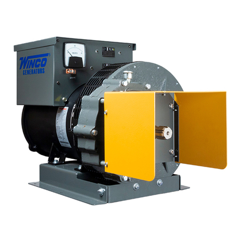
The WINCO rotating armature power take-off generators are
designed primarily for farm use as a standby electrical power
supply, utilizing the power take-off of a tractor or truck as the
prime mover. This PTO drive generator will provide, 120/240V
single phase, 60Hz electrical service when properly driven.
NOTE: The prime mover which drives the generator must be
capable of delivering approximately 2 HP per 1000 watts
output from the generator. Observe input RPM specifications.
The generator may be foundation mounted for use as standby
power source, or trailer mounted, and used as portable
electrical power sources for areas where commercial power
is not readily available, such as out buildings.
This generator includes a color coded voltmeter to warn
against high or low voltage, three output power receptacles,
an overload protection circuit, and an electronic excitation
circuit. To reduce maintenance problems, the coupling
between the generator input shaft and rotor consists of
precision helical gearing rather than a chain link drive. The
input shaft is a 1 1/8 in. diameter smooth shaft with a keyway
and center drilled for a roll pin. Both must be used at all
times.
The factory thoroughly tests each generator before shipment.
All are continuous duty rated.
IMPORTANT: THE MANUFACTURER STRONGLY RECOM-
MENDS RUNNING THE GENERATOR UNDER LOAD AT
LEAST ONCE A MONTH IN ORDER TO EVAPORATE ANY
ACCUMULATED MOISTURE CONDENSATION.
UNPACKING
CAUTION: Equipment Damage
DO NOT invert generator during unpacking. The Gearcase
contains oil which will leak out if inverted during unpacking.
Unpack the generator as follows:
1. Remove the carton.
2. Examine the unit for damage.
3. Find the small subpack carton packed in the large carton.
Be careful not to throw away the subpack carton with the
large carton.
4. Open the subpack carton and make sure it contains:
a. Generator instruction manual
b. Load disconnect plug (disassembled, in bag)
5. Remove the four bolts which hold down the generator feet
to the pallet.
6. Lift the generator from the pallet by means of the lifting eye
on the top of the generator.
7. Inspect the generator carefully for freight loss or damage.
If loss or damage is noted at time of delivery, require that
the person making the delivery make note of the loss or
damage on the freight bill, or sign the consigner’s memo
of the loss or damage. Contact the carrier for claim
procedures.
When loss or damage is noted after delivery, segregate the
damaged material, and contact the carrier for claim proce-
dures.
“Concealed damage” means damage to the contents of a
package which is not evident when the package is delivered
by the carrier, but which is discovered later. The carrier or
carriers are responsible for merchandise lost or damaged in
transit. The title to the goods rests with the consignee when
the goods are shipped FOB factory, and only the consignee
can legally file claims. Two years are allowed in which to file
suit after a claim is disallowed in writing by the carrier.
Assembly
The only assembly work required after unpacking the genera-
tor is to assemble the load disconnect plug, which is con-
tained in a bag in the subpack carton packed in the generator
crate.
The bag contains an instruction sheet, 2 plug bodies, four
contacts, two handle and the hardware to assembly the
disconnect plug. You will need to purchase the appropriate
length of fine stranded copper wire for your application in order
to complete the assembly of the disconnect plug. DO NOT
USE SO CABLE - USE SINGLE LEAD WELDING CABLE
The following wire sizes are recommended for each unit.
Generator Size
Model AWG Insulation
25PTOC #4 Neoprene/THHN
If you require different inserts or contacts for local code,
WINCO has a variety of different inserts and contacts avail-
able. Contact the factory at 507-357-6831 for pricing.
Figure 1
SINGLE PHASE
4 WIRE CONNECTION
CONTACTS
All 4 contacts
must be used.
