Knowles KAS-33100-0004 MUSKIE User manual

USERS GUIDE
KAS-33100-0004 “MUSKIE” MICROPHONE
EVALUATION KIT
knowles.com | KAS-33100-0004 Muskie Microphone Evaluation Kit
©2019, Knowles Electronics, LLC, Itasca, IL, USA, All Rights Reserved.
SiSonic, Knowles and the logo are trademarks of Knowles Electronics, LLC.
Figure 1: KC10143 Muskie Assembly
KIT DESCRIPTION
The KAS-33100-0004 Muskie microphone evaluation kit allows for
simple and easy evaluation of Knowles SiSonic™ MEMS microphones.
•Evaluate two input channels of audio from multiple MEMS
microphone types.
•Microphone types include single and differential Analog
MEMS microphones, Digital PDM MEMS microphones, and
Digital I2S MEMS microphones.
•Wide dynamic range (varies with microphone types and
audio path).
•Selectable Clock Frequencies, Voltages, and Gains.
•Multiple Audio Outputs – XLR, 3.5mm Headset Jack, USB
Audio.
SIMPLE QUICK START
1. Place suitable microphone assembly correctly into socket.
2. Select audio path and audio signal level.
3. Select Mic voltage and digital clock (if applicable).
4. Connect desired output (XLR, Headset, or USB).
5. Connect USB Cable and turn Power On.
KIT CONTENTS
•
KC10143-xxx Muskie Evaluation Board (Note: xxx denotes
assembly revision number)
•
USB A to USB Micro cable power cable
•
KCA2733 Flex Adapter Assembly (3 Total)
Note: The evaluation kit requires assembled MEMS
microphones. Usable assemblies include microphones
mounted to “flex” circuit cards or coupon boards. The kit
does NOT include assembled Knowles MEMS microphones.
Microphone assemblies are available separately from a
Knowles distributer.
Figure 2: Mic on Flex Assembly Example
For additional Muskie evaluation kit information, electrical
documentation, or flex circuit assembly information visit the Knowles
website. https://www.knowles.com/subdepartment/evaluation-kits/dpt-
microphones/subdpt-sisonic-surface-mount-mems.
The Muskie evaluation kit is for the evaluation of the Knowles
Electronics’ line of MEMS microphones. In some instances the eval kit
may limit overall microphone performance.
THE KITS’ INTENDED USE IS TO SUPPORT R&D
ACTIVITIES, AND IS NOT INTENDED FOR QUALIFICATION
OR PRODUCTION TEST USE.

KNOWLES – KAS-33100-0004 “MUSKIE” MICROPHONE EVALUATION KIT USERS GUIDE
knowles.com | KNOWLES – KAS-33100-0004 “MUSKIE” MICROPHONE EVALUATION KIT USERS GUIDE
©2019, Knowles Electronics, LLC, Itasca, IL, USA, All Rights Reserved.
2SiSonic, Knowles and the logo are trademarks of Knowles Electronics, LLC.
2
BLOCK DIAGRAM
MicVDD
MicVDD
MicVDD
ANA
Mic1
ANA
Mic2
Dig
Mic1
Dig
Mic2
I2S
Mic1
I2S
Mic2
Single/Diff
Selector
Single/Diff
Selector
PDM -> I2S
Converter
AU7002
Voltage Level
shifter
PDM Data
Mic Clk
I2S Data
I2S Data
WS
WS
LSCLK
LSCLK
74AVC6T622
Digital Data
Selector
74LVC157
SData
BCLK
LRCLK
SDIN
Select PDM
Select I2S
PCM17 4
192 Hz
24bit D/A
LRCLK
BCLK
SCLK
OPA1632
Ana/Dig
Selector
Ana/Dig
Selector
ROUT-
LOUT+
LOUT-
Max
BW=37.5KHz
@4.8MHz
I2S Data
Mic Clk
PDM Data
+19db
LT6232
27MHz
XTAL
MCL
M 2705
AUDIO CL
SOURCE
FREQ SELECT
JUMPER
CL DIVIDER
CIRCUITS
SCL
RST
LRCL
BCL
CLOCK
GENERATOR
Base Clock
Freq Sel
74LVC157
19.2MHz
XTAL
3.3V
2.75V
1.8V
MicVDD
USB
Micro B
VBUS
TPS65133
RT6150
3.3v
800mA
FILTVBUS 3D3 -5VA
+5VA
LDK220
Source
Current
ADJ VDD
SELECTABLE
VDD
CURRENT
SENSE
POWER SUPPLIES
0.0
Selectable Attenuation
0dB, -4dB, -15dB, -19dB
OPA1632
OPA1632
LT6232
+0db
Left Diff
Audio
Right Diff
Audio
1
2
3
1
2
3
Headset
Jack
MAX9722A
USB
Audio
USB CODEC
PCM2900CDB
BW = 48 Hz
Selectable Attenuation
0dB, -4dB, -15dB, -19dB
LOUT+
LOUT-
USB Micro B
Connector
Figure 3: KC10143 Muskie Board Block Diagram

KNOWLES – KAS-33100-0004 “MUSKIE” MICROPHONE EVALUATION KIT USERS GUIDE
knowles.com | KNOWLES – KAS-33100-0004 “MUSKIE” MICROPHONE EVALUATION KIT USERS GUIDE
©2019, Knowles Electronics, LLC, Itasca, IL, USA, All Rights Reserved.
3SiSonic, Knowles and the logo are trademarks of Knowles Electronics, LLC.
3
4Adjustab e
VDD
5
MIC
Current
5
6
Digita
MIC
Se ector
77
88
Ana og
Mic1
Ana og
Mic1
Digita
Mic1
Digita
Mic2 I2S Mic2I2S Mic1
10
18 18
10
11
Dua Mic
Test
Jumpers
Ana og Mic
Type
Se ectors
Ana og/Digita
Mic Type
Se ectors
Right Channe
Audio Output 12
1
2
Power
Switch
USB Micro B
Power
Connector
3
VDD
Se ector
17
16
Left Channe
Audio Output
Headset Jack
Audio Output
15
13
14
USB Micro B
Audio
Connector
Digita Mics
C ock Frequency
Se ector
Audio Gain
Se ectors
Figure 4: KC10143 Muskie Functional Description
FUNCTIONAL DESCRIPTION
1. Main Power Switch
Slide switch. When placed in the ON position will enable the
internal voltage regulators and support circuitry. If all internal
supplies power up correctly the POWER GOOD LED will
turn on.
2. USB connector for main power.
USB Micro B connector. Source power for Muskie board.
Knowles recommends using a USB based battery similar to
Insignia model # MB5202B for supplying clean power to kit.
3. Microphone VDD Selector
Slide switch allows microphone voltage selection. Supports
common microphone voltages, +3.3V, +2.75V, and +1.8V.
The ADJ selection generates unique VDD voltages.
4. Adjustable VDD
Setting the VDD SELECTOR to ADJ enables the VDD-ADJ
potentiometer to generate a custom VDD voltage. The
adjustable voltage range is from ~+1.6V to ~+3.65V.
Refer to microphone specifications for acceptable input
voltages.
5. MIC Current Jacks
Banana jack compatible, for measuring current using an
external current meter. Note: remove jumper labeled
BYPASS to enable.
6. Digital MIC Selector
Sets signal path for digital microphones. Select between
PDM digital and I2S digital.

KNOWLES – KAS-33100-0004 “MUSKIE” MICROPHONE EVALUATION KIT USERS GUIDE
knowles.com | KNOWLES – KAS-33100-0004 “MUSKIE” MICROPHONE EVALUATION KIT USERS GUIDE
©2019, Knowles Electronics, LLC, Itasca, IL, USA, All Rights Reserved.
4SiSonic, Knowles and the logo are trademarks of Knowles Electronics, LLC.
4
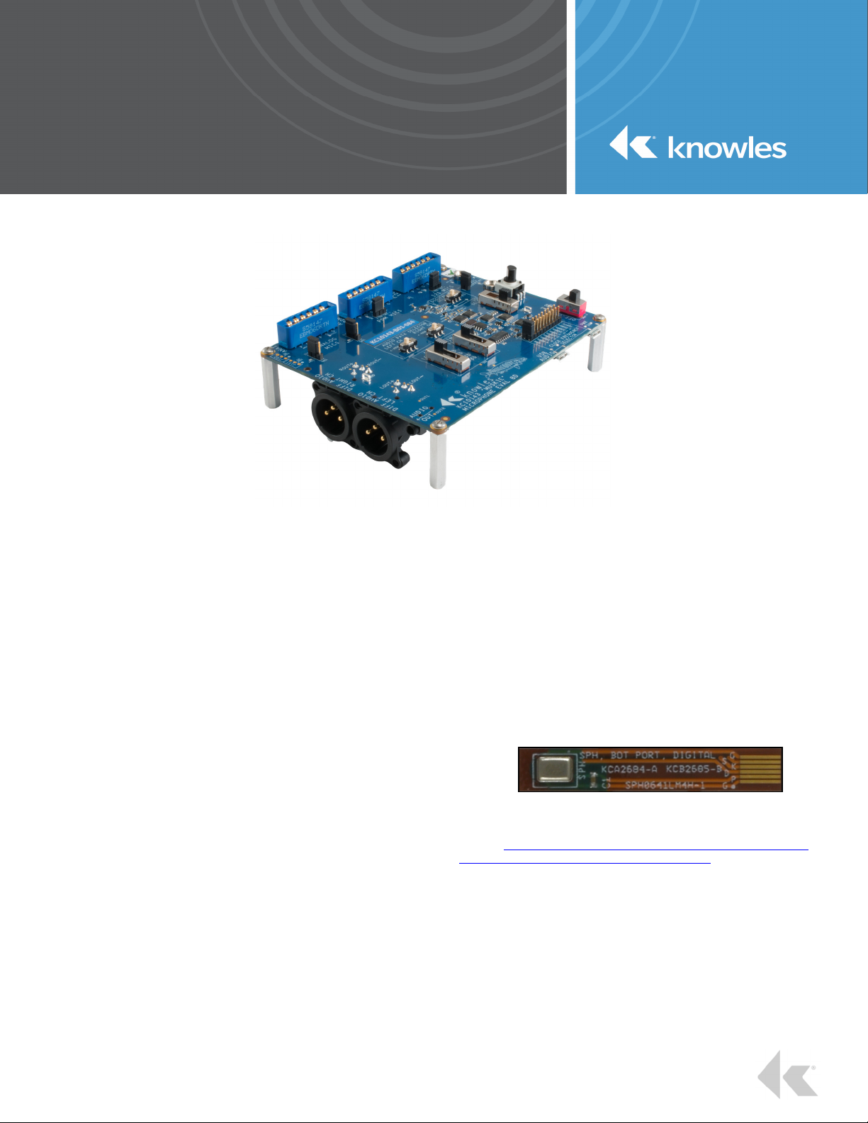
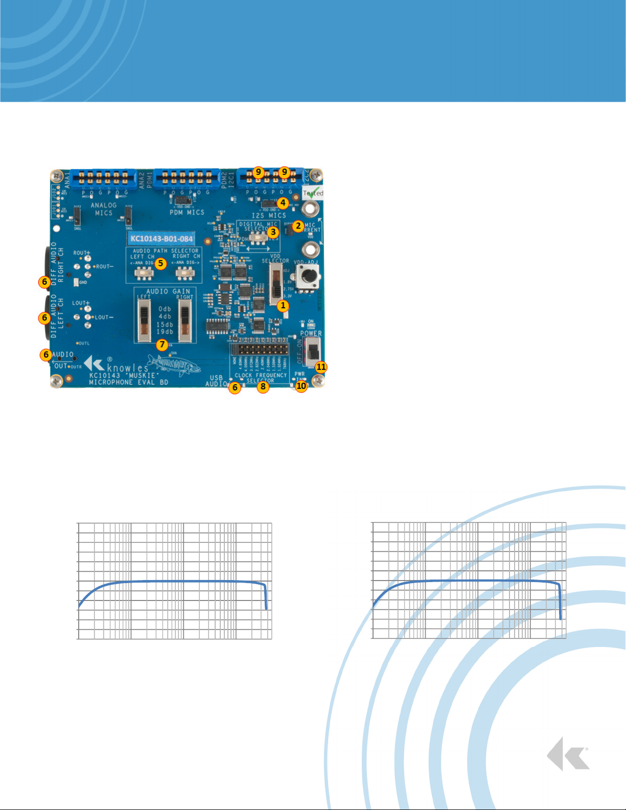
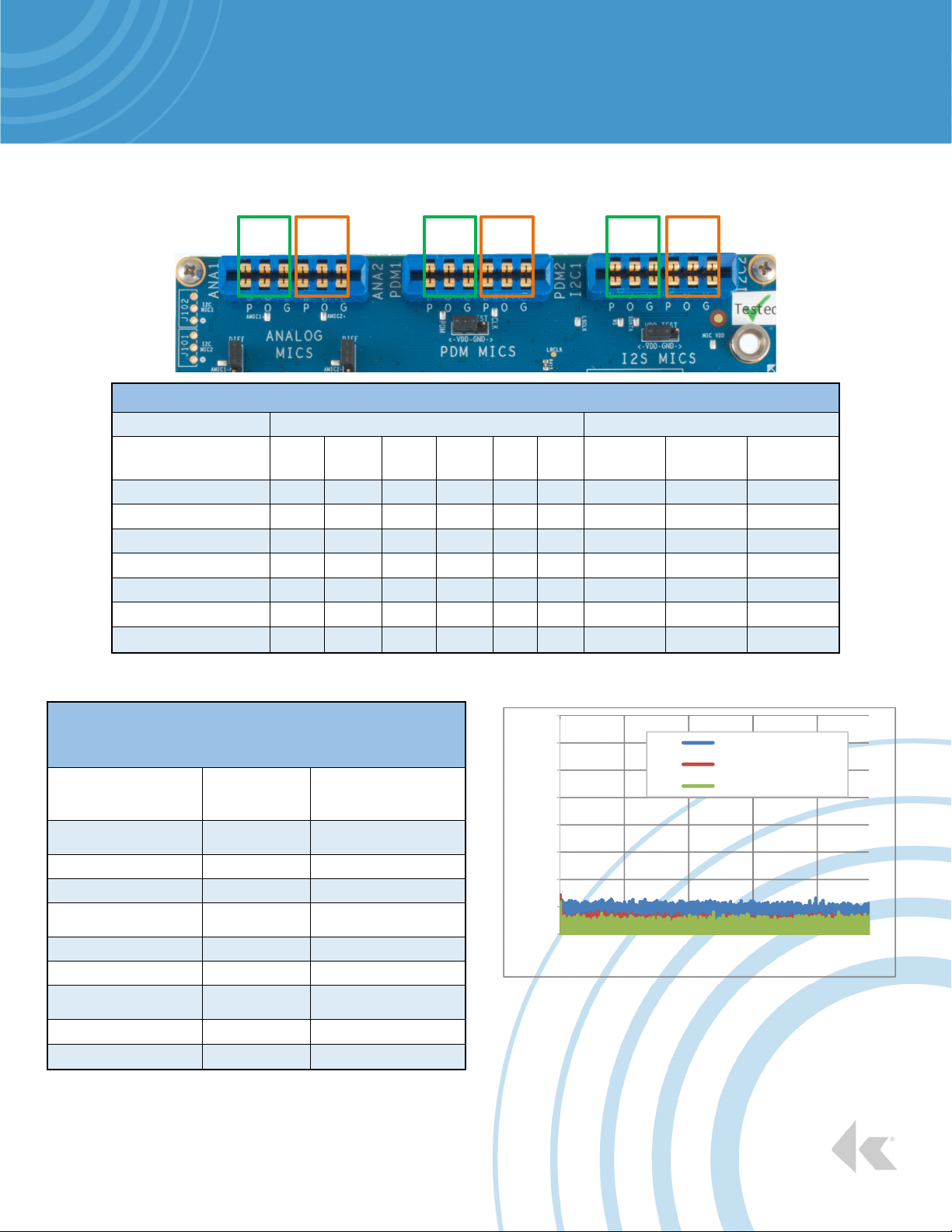
7. I2S Digital Mic Connector
The socket connector can accommodate a maximum of two
coupons. Orient the flex adapter board (KCA2733) to align
the “P O G” markings with the “P O G” markings on the
Muskie board.
8. PDM Digital Mic Connector
The socket connector can accommodate a maximum of two
coupons. Orient the flex adapter board (KCA2733) to align
the “P O G” markings with the “P O G” markings on the
Muskie board.
9. Analog Mic Connector
The socket connector can accommodate a maximum of two
coupons. Orient the flex adapter board (KCA2733) to align
the “P O G” markings with the “P O G” markings on the
Muskie board.
10. Analog Mic Type Selection Jumper
Select between Analog Differential Mic and Analog Single
ended Mic. Left jumper is selector for ANA1 connector
socket. Right jumper is selector for ANA2 connector socket.
11. Analog/Digital Mic Type Selector
Select independently left and right channels between analog
or digital microphone paths.
12. Right Channel Audio Output
Right channel differential analog audio output. Audio is
output thru a male XLR connector with the following pinouts.
Pin 1 – GND
Pin 2 – Right channel positive audio signal
Pin 3 – Right channel negative audio signal
13. Left Channel Audio Output
Left channel differential analog audio output. Audio is output
thru a male XLR connector with the following pinouts.
Pin 1 – GND
Pin 2 – Left channel positive audio signal
Pin 3 – Left channel negative audio signal
14. Headset Audio Output Jack
3.5mm standard analog headset jack passing stereo audio.
15. Audio Level Selectors
Independent left and right channel gain/attenuation settings.
16. Digital Mics Clock Frequency Selector
PDM/I2S system clock generator. Select between nine
useable digital microphone frequencies.
768KHz
1.024MHz
1.536MHz
2.048MHz
2.4MHz
2.822MHz
3.072MHz
4.096MHz
4.8MHz
NONE – Disables the clock generator circuit.
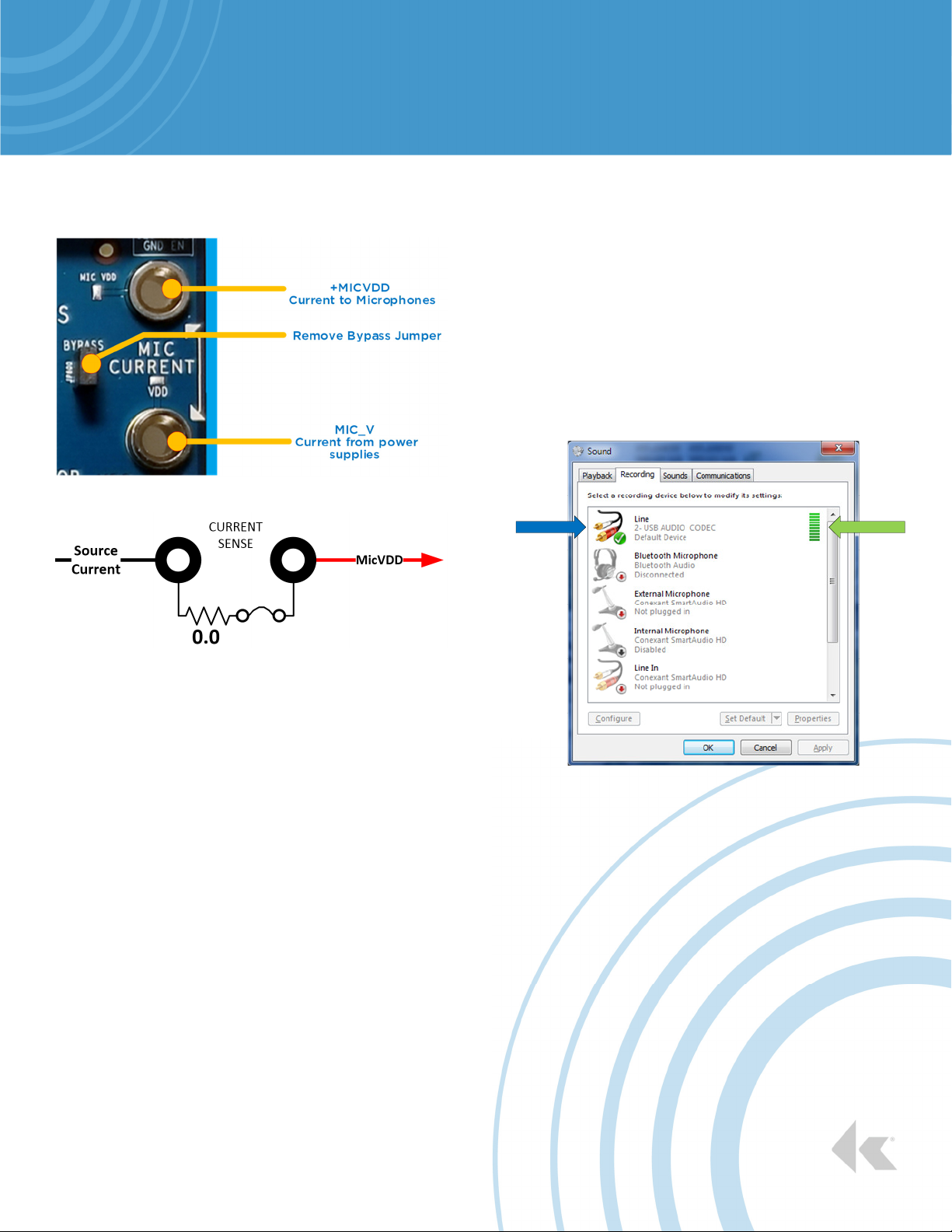
17. USB Audio Connector
USB Micro B connector for steaming USB audio to a PC.
The Muskie board uses a generic Windows 7 USB audio
driver. No external software driver installation nessessary.
When connected and powered the device will appear as an
USB Audio Codec under the Recording tab of the Sound
window.
Figure 5: PC Sound Window
18. Dual Mic Test Jumpers
PDM2 and I2S2 sockets VDD pin can be set to VDD or
GND, independent of PDM1 or I2S1 sockets. Used for
stereo Mic VDD testing.

KNOWLES – KAS-33100-0004 “MUSKIE” MICROPHONE EVALUATION KIT USERS GUIDE
knowles.com | KNOWLES – KAS-33100-0004 “MUSKIE” MICROPHONE EVALUATION KIT USERS GUIDE
©2019, Knowles Electronics, LLC, Itasca, IL, USA, All Rights Reserved.
5SiSonic, Knowles and the logo are trademarks of Knowles Electronics, LLC.
5
FLEX ADAPTER (KCA2733)
The KCA2733 flex adapter assembly is comprised of
•One KCB2734 printed circuit board.
•One 0.1μF 10% bypass capacitor.
•One AVX Corp 8 position connector
Part# 046288008000846+.
Insert the flex microphone into the KCA2733 flex adapter. Flex board is
inserted with copper contacts face down. Lock the flex into the adapter
by closing the connector.
Figure 6: Flex adapter - correct installation of bottom port mic
Note: Flex adapter board’s correct insertion orientation.
Figure 7: Flex adapter - incorrect installation of bottom port mic
Note: Incorrect flex insertion. The flex PCB traces should NOT be
visible.
KCA2733
Figure 8: Correct Flex Adapter Insertion into Muskie board
Note: P O G text on flex adapter aligns with P O G text on Muskie
board.
Figure 9: Flex adapter schematic
Refer to Knowles application note AN18 for additional flex/coupon
information. AN18 is available at the Knowles website.
https://www.knowles.com/subdepartment/evaluation-kits/dpt-
microphones/subdpt-sisonic-surface-mount-mems.
KCA2733 Flex Adapter

KNOWLES – KAS-33100-0004 “MUSKIE” MICROPHONE EVALUATION KIT USERS GUIDE
knowles.com | KNOWLES – KAS-33100-0004 “MUSKIE” MICROPHONE EVALUATION KIT USERS GUIDE
©2019, Knowles Electronics, LLC, Itasca, IL, USA, All Rights Reserved.
6SiSonic, Knowles and the logo are trademarks of Knowles Electronics, LLC.
6
TAKING CURRENT
MEASUREMENTS
Figure 10: MIC Current Setup
Figure 11: Current sense electrical circuit
•Attach current measuring equipment across
the Mic Current terminals.
The terminal located closest to the top of the board is
+MICVDD. The other terminal is the power supply
source current.
Remove the BYPASS jumper to enable.
Note: The +MICVDD signal is bussed across all
Muskie board microphone connectors. The current
measured will be a total of all microphones
connected.
USB AUDIO PATH SETUP
The Muskie board uses a Stereo Audio Codec with USB
Interface. The USB controller uses standard Windows/Mac
USB audio drivers.
Windows - To verify the USB audio path is functioning connect
USB cable from Muskie board USB Audio connector to PC.
Slide Muskie board power switch to ON. From the PC, open
Control Panel –› Hardware and Sound –› Sound.
Click on the Recording tab and verify the USB AUDIO CODEC
appears.
The bar graph on the right will indicate audio detection when a
suitable microphone is plugged in and configured correctly.
Figure 12: PC Sound Panel
Audio DetectionMuskie Board

KNOWLES – KAS-33100-0004 “MUSKIE” MICROPHONE EVALUATION KIT USERS GUIDE
knowles.com | KNOWLES – KAS-33100-0004 “MUSKIE” MICROPHONE EVALUATION KIT USERS GUIDE
©2019, Knowles Electronics, LLC, Itasca, IL, USA, All Rights Reserved.
7SiSonic, Knowles and the logo are trademarks of Knowles Electronics, LLC.
7
QUICK START SETTINGS FOR ANALOG MICROPHONES
Figure 13: Analog Microphone Setup
The KC10143 Muskie board supports both single
ended and differential microphones. Microphone
types may be mixed.
1. Set VDD voltage level.
2. Verify Microphone Current Bypass jumper
installed. Alternatively see section on Taking
Current Measurements.
3. Set analog microphone type. The left jumper
posts set microphone type for ANA1 socket. The
right jumper posts set microphone type for ANA2
socket. Mixing microphone types is allowed (i.e.
1- Diff Mic, 1-Single ended Mic).
4. Set Audio Path selector to ANA for the
corresponding socket.
5. Set signal gain.
6. Make connection to desired audio output. All
audio output paths (XLR, Headset, USB) pass
audio simultaneously.
7. Insert a suitable 5V power source into USB
Power In connector.
8. Insert microphones into socket using the correct
orientation. (Align P O G markings)
9. Set power switch to ON.
Magnitude Response Analog Input - XLR Output
Figure 14: Analog Input – XLR Output
Magnitude Response Analog Input-Headset Output
Figure 15: Analog Input – Headset Jack Output
-18
-15
-12
-9
-6
-3
0
3
6
9
12
15
18
10 100 1000 10000
Sensitivity Relative to 1kHz (dB)
Frequency (Hz)
-18
-15
-12
-9
-6
-3
0
3
6
9
12
15
18
10 100 1000 10000
Sensitivity Relative to 1kHz (dB)
Frequency (Hz)

KNOWLES – KAS-33100-0004 “MUSKIE” MICROPHONE EVALUATION KIT USERS GUIDE
knowles.com | KNOWLES – KAS-33100-0004 “MUSKIE” MICROPHONE EVALUATION KIT USERS GUIDE
©2019, Knowles Electronics, LLC, Itasca, IL, USA, All Rights Reserved.
8SiSonic, Knowles and the logo are trademarks of Knowles Electronics, LLC.
8
QUICK START SETTINGS FOR PDM DIGITAL MICROPHONES
Figure 16: PDM Microphone Setup
The KC10143 Muskie board supports both mono and
stereo digital microphone configurations.
Microphone types may be mixed.
1. Set VDD voltage level.
2. Verify Microphone Current Bypass jumper
installed. Alternatively see section on Taking
Current Measurements.
3. Set Digital Mic Selector switch to PDM.
4. Install Mic2 VDD Test Jumper to VDD
(default setting).
5. Set Audio Path selector to DIG for the
corresponding socket.
6. Make connection to desired audio output. All
audio output paths (XLR, Headset, USB)
pass audio simultaneously.
7. Set signal gain.
8. Install jumper for desired PDM clock
frequency.
9. Insert microphones into socket using the
correct orientation.
10. Insert a suitable 5V power source into USB
Power In connector.
11. Set power switch to ON
Magnitude Response PDM Input - XLR Output
Figure 17: PDM Input – XLR Output
Magnitude Response PDM Input-Headset Output
Figure 18: PDM Input – Headset Jack Output
-18
-15
-12
-9
-6
-3
0
3
6
9
12
15
18
10 100 1000 10000
Sensitivity Relative to 1kHz (dB)
Frequency (Hz)
PDM CLK @4.8MHz
PDM CLK @3.072MHz
PDM CLK @1.532MHz
PDM CLK @768KHz
-18
-15
-12
-9
-6
-3
0
3
6
9
12
15
18
10 100 1000 10000
Sensitivity Relative to 1kHz (dB)
Frequency (Hz)
PDM CLK @4.8MHz
PDM CLK @3.072MHz
PDM CLK @1.532MHz
PDM CLK @768KHz

KNOWLES – KAS-33100-0004 “MUSKIE” MICROPHONE EVALUATION KIT USERS GUIDE
knowles.com | KNOWLES – KAS-33100-0004 “MUSKIE” MICROPHONE EVALUATION KIT USERS GUIDE
©2019, Knowles Electronics, LLC, Itasca, IL, USA, All Rights Reserved.
9SiSonic, Knowles and the logo are trademarks of Knowles Electronics, LLC.
9
QUICK START SETTINGS FOR I2S MICROPHONES
Figure 19: I2S Microphone Setup
The KC10143 Muskie board supports both mono and
stereo digital microphone configurations.
Microphone types may be mixed.
1. Set VDD voltage level.
2. Verify Microphone Current Bypass jumper
installed. Alternatively see section on Taking
Current Measurements.
3. Set Digital Mic Selector switch to I2S.
4. Install VDD Test Jumper to VDD (default
setting).
5. Set Audio Path selector to DIG for the
corresponding socket.
6. Make connection to desired audio output. All
audio output paths (XLR, Headset, USB)
pass audio simultaneously.
7. Set signal gain.
8. Install jumper for desired I2S clock
frequency.
9. Insert microphones into socket using the
correct orientation.
10. Insert a suitable 5V power source into USB
Power In connector.
11. Set power switch to ON.
Magnitude Response I2S Input – XLR Output
Figure 20: I2S Input – XLR Output
Magnitude Response I2S Input-Headset Output
Figure 21: I2S Input – Headset Jack Output
-18
-15
-12
-9
-6
-3
0
3
6
9
12
15
18
10 100 1000 10000
Sensitivity Relative to 1kHz (dB)
Frequency (Hz)
-18
-15
-12
-9
-6
-3
0
3
6
9
12
15
18
10 100 1000 10000
Sensitivity Relative to 1kHz (dB)
Frequency (Hz)

KNOWLES – KAS-33100-004 “MUSKIE” MICROPHONE EVALUATION KIT USERS GUIDE
knowles.com | KNOWLES – KAS-33100-0004 “MUSKIE” MICROPHONE EVALUATION KIT USERS GUIDE
©2019, Knowles Electronics, LLC, Itasca, IL, USA, All Rights Reserved.
10 SiSonic, Knowles and the logo are trademarks of Knowles Electronics, LLC.
10
TYPICAL CHARACTERISTICS – OPERATING PERAMETERS
ANA1 ANA2 PDM1 PDM2 I2S1 I2S2
Microphone
Microphone Microphone
Microphone Compatibility
CompatibilityCompatibility
Compatibility
Mapping
MappingMapping
Mapping
Mic Types
Mic TypesMic Types
Mic Types
Sullins Connector Socket
Path switch settings
Path switch settingsPath switch settings
Path switch settings
ANA
ANAANA
ANA
1
11
1
ANA
ANAANA
ANA
2
22
2
PDM
PDMPDM
PDM
1
11
1
PDM
PDMPDM
PDM
2
22
2
I2S
I2SI2S
I2S1
11
1
I2S
I2SI2S
I2S2
22
2
Left
Left Left
Left
Channel
ChannelChannel
Channel
ight
ight ight
ight
Channel
ChannelChannel
Channel
Digital Mic
Digital Mic Digital Mic
Digital Mic
Selector
SelectorSelector
Selector
Ana og -Ana og
ANA ANA N/A
Ana og-PDM
ANA DIG PDM
Ana og-I2S
ANA DIG I2C
Ana og-PDM
DIG ANA PDM
Ana og-I2S
DIG ANA I2C
PDM-PDM
DIG DIG PDM
I2S-I2S
DIG DIG I2C
Table 1: Microphone Mapping
Signal Path Throughput
Muskie Audio Signal Path Attenuation
Muskie Audio Signal Path AttenuationMuskie Audio Signal Path Attenuation
Muskie Audio Signal Path Attenuation
(Audio Gain switch set to 0db)
(Audio Gain switch set to 0db)(Audio Gain switch set to 0db)
(Audio Gain switch set to 0db)
Audio Type
Audio TypeAudio Type
Audio Type
Audio
Audio Audio
Audio
Path
PathPath
Path
Approximate
ApproximateApproximate
Approximate
Gain
GainGain
Gain
@ 1KHz
@ 1KHz@ 1KHz
@ 1KHz
Ana og Sing e or
Differentia XLR 0db
PDM XLR -6db(Vrms/FS)
I2S XLR -0db(Vrms/FS)
Ana og Sing e or
Differentia Headset -6db
PDM Headset -12db(Vrms/FS)
I2S Headset -6db(Vrms/FS)
Ana og Sing e or
Differentia USB -34db
PDM USB -40db
I2S USB -34db
Table 2: Muskie Signal Path
Noise Floor (No Signal)
Figure 22: Noise Floor
-160
-140
-120
-100
-80
-60
-40
-20
0
0 10000 20000 30000 40000
Noise Floor Level (db)
Frequency (Hz)
Noise Floor ANA
Noise Floor PDM
Noise Floor I2S

KNOWLES – KAS-33100-004 “MUSKIE” MICROPHONE EVALUATION KIT USERS GUIDE
knowles.com | KNOWLES – KAS-33100-0004 “MUSKIE” MICROPHONE EVALUATION KIT USERS GUIDE
©2019, Knowles Electronics, LLC, Itasca, IL, USA, All Rights Reserved.
11 SiSonic, Knowles and the logo are trademarks of Knowles Electronics, LLC.
11
Muskie Test Conditions:
Analog Microphone (Winfrey) connected and powered.
Digital Microphone (Cameron) connected and powered.
Gain setting = 0db.
MicVDD = 3.3V.
Output path = XLR
External audio source generating 1KHz or 40KHz tones.
Clock (if applicable) = 3.0724MHz
Example: Analog microphone measurement of
ambient (room) noise with 1KHz tone.
Figure 23: Analog Mic at ambient room with 1KHz signal applied
Example: Analog ultrasonic microphone
measurement of ambient (room) noise with 40KHz
tone.
Figure 24: Analog Mic at ambient room with 40KHz signal applied
Example: PDM microphone measurement of
ambient (room), 3.072MHz Clock, and 1KHz tone.
Figure 25: PDM Mic at ambient room with 1KHz signal applied
Note: PDM microphones will have a bandwidth limitation
due to the ADAU7002 PDM to I2S converter IC. This
limitation will vary with clock frequency.
Example: PDM microphone measurement of
ambient (room), 3.072MHz Clock, and 40KHz tone.
Figure 26: PDM Mic at ambient room with 1KHz signal applied
-160
-140
-120
-100
-80
-60
-40
-20
0
10.0 100.0 1000.0 10000.0
Noise Floor Level (db)
Frequency (Hz)
Frequency (Hz)Frequency (Hz)
Frequency (Hz)
Example: Analog Microphone
Example: Analog MicrophoneExample: Analog Microphone
Example: Analog Microphone
-160
-140
-120
-100
-80
-60
-40
-20
0
0 20000 40000 60000 80000
Noise Floor Level (db)
Frequency (Hz)
Example: Analog Ultrasonic Microphone
Example: Analog Ultrasonic MicrophoneExample: Analog Ultrasonic Microphone
Example: Analog Ultrasonic Microphone
-160
-140
-120
-100
-80
-60
-40
-20
0
10 100 1000 10000
Noise Floor Level (db)
Frequency (Hz)
Frequency (Hz)Frequency (Hz)
Frequency (Hz)
Example: PDM Microphone
Example: PDM MicrophoneExample: PDM Microphone
Example: PDM Microphone
-160
-140
-120
-100
-80
-60
-40
-20
0
0 20000 40000 60000 80000
Noise Floor Level (db)
Frequency (Hz)
Frequency (Hz)Frequency (Hz)
Frequency (Hz)
Example: PDM Ultrasonic Microphone
Example: PDM Ultrasonic MicrophoneExample: PDM Ultrasonic Microphone
Example: PDM Ultrasonic Microphone

KNOWLES – KAS-33100-004 “MUSKIE” MICROPHONE EVALUATION KIT USERS GUIDE
12
Knowles Corporation
1151 Maplewood Drive
Itasca, Illinois 60143
Phone: 1 (630) 250-5100
Fax: 1 (630) 250-0575
sales@knowles.com
Model/Reference Number:
KAS-33100-0004 Muskie Users Guide
2019, Knowles
12
INFORMATION
FOR FURTHER INFORMATION ON TECHNOLOGY,
DELIVERY TERMS AND CONDITIONS AND PRICES,
PLEASE CONTACT A KNOWLES REPRESENTATIVE.
© 2019, KNOWLES ELECTRONICS, LLC, ITASCA, IL USA.
ALL RIGHTS RESERVED. KNOWLES AND THE LOGO
ARE TRADEMARKS OF KNOWLES ELECTRONICS, LLC.
.
DISCLAIMER
THE INFORMATION GIVEN IN THIS DOCUMENT SHALL
IN NO EVENT BE REGARDED AS A GUARANTEE OF
CONDITIONS OR CHARACTERISTICS. WITH RESPECT
TO ANY EXAMPLES GIVEN HEREIN, ANY TYPICAL
VALUES STATED HEREIN AND/OR ANY INFORMATION
REGARDING THE APPLICATION OF THE DEVICE,
KNOWLES ELECTRONICS, LLC HEREBY DISCLAIMS
ANY AND ALL WARRANTIES AND LIABILITIES OF ANY
KIND, INCLUDING WITHOUT LIMITATION WARRANTIES
OF NON-INFRINGEMENT OF INTELLECTUAL
PROPERTY RIGHTS OF ANY THIRD PARTY
REVISION HISTORY
Revision
Description Date
1 Initia Re ease 5/23/19
2 B ock diagram update 6/28/19
3
4
5
This manual suits for next models
1
Table of contents
Other Knowles Motherboard manuals