Knox MedVault 2.5 Mini User manual

MedVault®
Retrofit Kit PCBA
Installation Guide
1601 W. Deer Valley Road, Phoenix, AZ 85027
Phone: 800-552-5669 ● Fax: 623-687-2299
www.knoxbox.com
OPE-MVUSER-0473-C
Warning
Treat this manual as a confidential document.
Limit access to authorized personnel.

OPE-MVUSER-0473-C The Knox Company ▪ MedVault®▪ ii
Copyright ®2019 by The Knox Company. All rights reserved.
The Knox Company, the Knox logo and all other Knox Company product or service names are
registered trademarks or trademarks of the Knox Company.
Restricted Rights Legend
U.S. GOVERNMENT RESTRICTED RIGHTS. UNPUBLISHED—RIGHTS RESERVED
UNDER THE COPYRIGHT LAWS OF THE UNITED STATES. Use, duplication, or disclosure is
subject to restrictions set forth in the FAR Section 52.227-14 Alt. III(g)(3), FAR Section 52.227-19, DFARS
252.227-7014(b), or DFARS 227.7202, as amended from time to time.
The Knox Company
1601 W. Deer Valley Road
Phoenix, AZ 85027, USA
(800) 552-5669 General Information
(866) 566-9269 Electronic Support
(623) 687-2290 Fax
Contacting the Knox Company, Limited Warranty and Order Terms
and Conditions
You can access the Knox Company web site at http://knoxbox.com. From this web site, you can obtain general
information about the company, customer support, products and career opportunities. You can also register and log
into the system to obtain software updates and new manuals. Your installation and use of the product is subject in
all respects to Knox’s limited warranties for products and Knox’s Order Terms and Conditions which are also
available at http://knoxbox.com.
Important Information for MedVault WiFi Units
FCC NOTICE
The RF module contained within this device complies with the rules set forth in Part 15 by the Federal
Communications Commission. Operation is subject to the following conditions:
1. This device may not cause harmful interference.
2. This device must accept any interference received, including interference that may cause undesired operation.
3. An approved antenna must be directly coupled to the module's RP-SMA connector.
4. The module must not be modified in any way. Coupling of external circuitry must not bypass the provided
connectors.
5. The antenna used for this transceiver must not be co-located or operated in conjunction with any other antenna or
transmitter.
Any changes or modifications could void the user's authority to operate the equipment.
This Class B digital apparatus complies with Canadian ICES-003.
Cet appareil numérique de la classe B est conforme à la norme NMB-003 du Canada.
This Device Contains: FCC ID: R68MTCHDRCT, IC ID: 3867A-MTCHDRCT or
FCC ID: YOPGS2100MIE, IC ID: 9154A-GS2100MIE. Refer to product label to determine which module is
installed.

OPE-MVUSER-0473-C The Knox Company ▪ MedVault®▪ 1
Contents
MedVault 2.5 Board Installation Instructions......................................................... 3
The Knox MedVault 2.5 circuit board includes the following updates:................. 3
The tools and materials needed for the installation includes the following items:
........................................................................................................................... 3
MedVault Retrofit Kit 91158 and 91160 Include the following:........................... 4
Safety precautions: ............................................................................................. 4
ESD Strap instructions………………………………………………………………………………..4
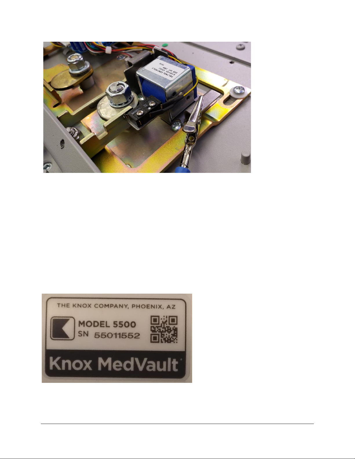
Serialized Labels ……………………………………………………………………………………. 4
Circuit Board Removal ........................................................................................ 6
Step #1 is Opening the MedVault .................................................................... 6
Step #2 Disconnect power and coax connection from back panel.................... 6
Step #3 Remove the tech key cover ................................................................ 6
Step #4 Unlock back cover .............................................................................. 7
Step #5 Remove the back plate ....................................................................... 7
Step #6 Unplug power to board and remove Wi-Fi board ................................ 7
Step # 7 Disconnect Lead wires....................................................................... 8
Step #8 Remove tape from board and unplug connections.............................. 8
Step #9 Remove screws from circuit board ..................................................... 9
Step #10 Unplug wiring on top of board .......................................................... 9
Step #11 Snip the Cable Tie........................................................................... 10
Installing Circuit Board ..................................................................................... 11
Step #12 Connect board ................................................................................ 11
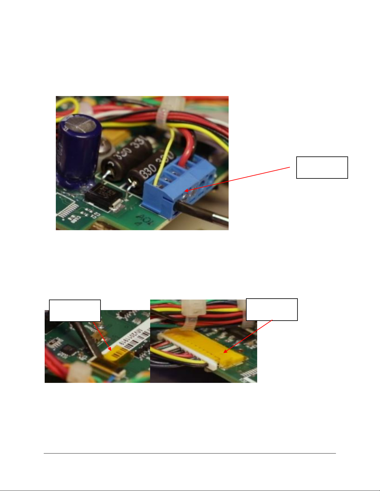
Step #13 Add Kapton tape to Connectors ...................................................... 12
Step #14 Fasten New board .......................................................................... 12
Step #15 Connect Wires to terminal block..................................................... 13
Step #16 Secure Reset Switch wire ............................................................... 13
Step #17 Move Antenna cable fasten back plate.......................................... 14
Step #18 Tech Lock back in ......................................................................... 14
Step #19 Tech Lock cover.............................................................................. 14
Step #20 Reconnect power and fasten back plate ......................................... 14
Step #21 Initial Set Up .................................................................................. 14
Step #22 Attach serial number label …………………………………………………… 15

OPE-MVUSER-0473-C The Knox Company ▪ MedVault®▪ 2
Step #23 Optional Step to Attach antenna to convert Wi-Fi Ready to Wi-Fi
Standard………………………………………………………………………………………………….. 15
Contact Technical Support.................................................................................... 16

OPE-MVUSER-0473-C The Knox Company ▪ MedVault®▪ 3
MedVault 2.5 Board Installation Instructions
The following instructions are for the following kits.
91158
RETROFIT KIT, PCBA, MAIN BOARD, MedVault® 2.5 Large
91160
RETROFIT KIT, PCBA, MAIN BOARD, MedVault® 2.5 Mini
The difference between the two kits is the length of the coax cable on the
circuit board and the serial numbers on the label. Make sure that the retrofit
kit matches the MedVault in which the board will be installed.
The following document shows the steps to remove the MedVault 2.0 board
and replace with the new 2.5 MedVault Board. Removing the MedVault 2.0
board and installing the new Knox MedVault 2.5 circuit board is a simple
process that should take approximately ten minutes to complete. The
MedVault 2.5 Circuit board will be required for using KnoxConnect cloud-
based software.
The Knox MedVault 2.5 circuit board includes the following
updates:
•Automatic PIN updates and audit history upload
•Management and reporting through KnoxConnect cloud-based
software
•Improved reliability
•New circuit board design and resilient firmware
•Optional use of Knox eLock and Knox eKey as an additional access
method or override
The tools and materials needed for the installation
includes the following items:
•#2 Phillips Screwdriver for 10/32 and 6/32 screws
•Flat head 3/32 screwdriver
•Fine point wire cutters
•Knox MedVault Tech key
•Knox MedVault 2.5 Retrofit kit which contains the new circuit board
and all additional materials needed to remove and replace the board.

OPE-MVUSER-0473-C The Knox Company ▪ MedVault®▪ 4
MedVault Retrofit Kit 91158 and 91160 Include the
following:
Quantity
Description
1
Cable Tie
1
PCA Main Board MedVault 2.5, with
battery, coax cable
1
Label, Alum MedVault 2.5 Serialized
2
Kapton Tape 0.25"X1"
1
Screw 6-32 X 0.25"
1
ESD Wrist strap
1
Retrofit MedVault 2.5 PCBA Installation
instructions
Safety precautions:
Always disconnect power to the MedVault when removing and installing
circuit boards. Knox also strongly recommends the installer wear safety
glasses. Always use a grounding strap (included in kit) while installing the
circuit board.
How to use grounding straps
ESD wrist straps is an antistatic device used to safely ground a person
working on sensitive electronic equipment to prevent the build-up of static
electricity on their body, which can result in electrostatic discharge (ESD).
ESD can damage the MedVault 2.5 board and cause the board not to work
properly.
To use the strap properly:
•Attach strap to wrist firmly. Make sure it is in contact with your skin.
•Attach grounding clip to solenoid bracket as shown. Note that the
back cover will need to be removed before clip is attached.

OPE-MVUSER-0473-C The Knox Company ▪ MedVault®▪ 5
Note: Serialized Labels, Do Not Discard
The retrofit kits contain a serialized circuit board with matching
label. Once the new circuit board is installed, the serial number of
the MedVault will change. Remove old label and replace with new
adhesive label which contains the new serial number on the
MedVault.
Important: It is important to track the serial number with the
correct circuit board, as the circuit board has been pre-programmed
to match the unit serial number on the label. Picture of the label is
below.

OPE-MVUSER-0473-C The Knox Company ▪ MedVault®▪ 6
Circuit Board Removal
Step #1 is Opening the MedVault
•The first step is to ensure the MedVault door is open
Step #2 Disconnect power and coax connection from back
panel
•Remove the 2 screws from the service panel
•Disconnect the power first and then coax connection for the antenna
Step #3 Remove the tech key cover
•Remove the 2 screws that secure the tech key cover.
Screw for
tech key
cover
Screw for
back panel
Screw for
tech key
cover

OPE-MVUSER-0473-C The Knox Company ▪ MedVault®▪ 7
Step #4 Unlock back cover
•Use your Knox Tech Key to unlock the back cover.
Step #5 Remove the back plate
•Remove the 9 screws from the back plate by using a #2 screwdriver
Step #6 Unplug power to board and remove Wi-Fi board
•If your MedVault is equipped with Wi-Fi Remove the top Wi-Fi board gently
by rocking back and forth
•MedVault 2.5 board is equipped with a Wi-Fi module on a single circuit board
Wi-Fi Board

OPE-MVUSER-0473-C The Knox Company ▪ MedVault®▪ 8
Step # 7 Disconnect Lead wires
•Next step is to disconnect the lead wires. First use a screwdriver to loosen
the screws on the terminal block and remove all three wires
Step #8 Remove tape from board and unplug connections
•Remove the Kapton tape from the keypad display connection and the IO
connector
•Disconnect keypad display connection, IO connector, and reset switch
connection
Terminal
Block
Kapton tape
on Keyboard
Kapton tape
IO
connector

OPE-MVUSER-0473-C The Knox Company ▪ MedVault®▪ 9
Step #9 Remove screws from circuit board
•Use a #2 screwdriver to remove the screws from the top of the circuit board
•Make sure to save the screws for installation of circuit board
Step #10 Unplug wiring on top of board
•Remove the ethernet connection from the board
•Now the old circuit board can be removed from the MedVault
Screws

OPE-MVUSER-0473-C The Knox Company ▪ MedVault®▪ 10
Step #11 Snip the Cable Tie
•Once the board is removed, snip the cable tie eyelet or standoff holding the
wiring bundle. Be sure to use a fine point wire cutter so that no wires are
cut.
Snip and remove
cable tie eyelet

OPE-MVUSER-0473-C The Knox Company ▪ MedVault®▪ 11
Installing Circuit Board
Step #12 Connect board
•Make sure that ESD wrist strap clip is attached to the solenoid
bracket
•You’re now ready to install the new MedVault 2.5 circuit board. The
connectors from left to right on the board: ethernet, Keypad display, and
the IO connector.
•Carefully install the keypad display connection. If installed
incorrectly, the keypad will not function properly.
•Carefully lift the black tab up, perpendicular to the board
•Insert the blue cable firmly
•Next, gently push down on the black tab to secure the keypad display
connector
Ethernet
Keypad display
connection
IO Connector
Keyboard display
connection in open
position

OPE-MVUSER-0473-C The Knox Company ▪ MedVault®▪ 12
Step #13 Add Kapton tape to Connectors
•Apply Kapton tape to the keypad display connection and the IO connection.
Kapton tape is included in the retrofit kit
•Kapton tape length will extend onto circuit board
Step #14 Fasten New board
•Fasten the circuit board in place. Use the original MedVault screws for 2 of
the locations.
•For the third location near the terminal block, use the screw that is included
in the retrofit kit. This screw is a different length
Screw from old
circuit board
Screw from
Retrofit Kit

OPE-MVUSER-0473-C The Knox Company ▪ MedVault®▪ 13
Step #15 Connect Wires to terminal block
•The first wire to install is the black ground wire which is position number 5 in
the terminal block. Insert the wire into the terminal block and tighten with a
screwdriver. The second wire to install is the red power wire in position #4.
The last wire to install is the yellow light wire in position number 1. Ensure
the wires are installed in the correct position in the terminal block.
Step #16 Secure Reset Switch wire
•Secure the white reset switch wire by using a cable tie. The reset switch will
not be needed with the new Circuit board. To reset the MedVault 2.5, press
the “#” key for 5 seconds.
Black Ground
Wire
Red Power Wire
Yellow light wire
Cable Tie on
reset switch

OPE-MVUSER-0473-C The Knox Company ▪ MedVault®▪ 14
Step #17 Move Antenna cable fasten back plate
•Move the coax antenna cable into the service panel area
•Use the same 9 screws to fasten back plate
Step #18 Tech Lock back in
•Install the Tech Lock
Step #19 Tech Lock cover
•Install the tech lock cover
Step #20 Reconnect power and fasten back plate
•Reconnect the power and antenna wires
•Fasten back plate with 2 screws
Step #21 Initial Set Up
•Now you are ready to power up the MedVault and set up KnoxConnect.
•Please refer to the Knox Networking guide KnoxConnect guide for setting up
your MedVault.
Antenna wire
Power wire

OPE-MVUSER-0473-C The Knox Company ▪ MedVault®▪ 15
Step #22 Attach Serial Number Label
•The serial number of the MedVault will change when the MedVault 2.5 circuit
board is installed. The new serial number is on the MedVault label that is
taped to the circuit board packaging.
•Once the circuit board is installed, remove the old label and attach the new
serial number label to the front of the MedVault.
Step #23 Optional Step to transform MedVault 2.0 Wi-Fi-Ready
to Wi-Fi Standard
If the current MedVault 2.0 has an antenna, this step is not necessary. Wi-Fi-
Ready MedVaults 2.0 do not have an antenna and in order for the MedVault 2.5
circuit board to function properly, an antenna must be installed. Antennas are not
included in the retrofit kit and must be purchased separately.
•Locate antenna connection on MedVault
•Tighten antenna connection
Antenna
connection
This manual suits for next models
1
Table of contents