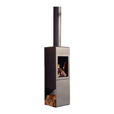
KOBE X-25F User manual

Kobe
NO Monteringsanvisning 2
Installation manual 4
GB
Art.no: FP-KOB00-000
Last updated: 27.11.2013
!kg

2 NO
Vekt
Huseier må forsikre seg om at gulvet tåler belastningen
i henhold til totalvekten på peisen. Vurder eventuelt
forsterkning av gulvet, spesielt i nye hus og dersom
området under peisen ikke har ekstra lettvegger
som understøtter. Ved montering på ytende tregulv,
bør peisen felles ned for å unngå at gulvet låses og
sprekker.
Brannmur
Frittstående peiser kan monteres uten brannmur.
Overhold alle sikkerhetsavstander til brennbare
materialer.
Tilkobling til pipe
Følg pipeprodusentenes spesikasjoner for tilkobling til
pipe. Tørrstable omrammingen og innsatsen
for nøyaktig
høyde og posisjon til røykinnføringen i pipen. Husk at
innsatsen ekspanderer under fyring. Omrammingen må
derfor aldri hvile på innsatsen, men ha en avstand på
minimum 2-3 mm. Innsatsen må heller ikke hvile mot
benkeplaten eller mot sidene.
Ved topptilslutning til stålpipe henviser vi til respektive
fabrikats monteringsanvisning.
Krav til gulvplate
Har ildstedet panoramadør og kun skal fyres lukket,
kreves det ved brennbart gulv 30 cm gulvplate foran
ildstedet, uansett høyde og dybde på ildstedet.
Gulvplatens bredde skal være minst like bred som luken
på innsatsen.
Akryl
Elementene skal limes med medfølgende akryl. Sørg
for at alle limater er frie for støv. For bedre heft kan
overatene vaskes. La overaten tørke før akrylen
strykes på. Når peisen er ferdig montert, etterfyll
skjøtene mellom elementene med akryl og jevn fugen
med en såpevåt svamp eller nger slik at det blir en
tydelig fordypning mellom elementene (FIG Z).
Småskader
Grunnet transport og håndtering kan det oppstå små
skader på peisen. Dette kan repareres med
akryl/lettsparkel. For perfekt resultat kan du sparkle og
slipe med egnet sparkelmasse. Mindre sår og
ujevnheter sparkles. Dersom såret er dypt eller det er en
større skade anbefales det å sparkle i ere omganger
med iselim eller sementsparkel for å unngå synk. Jevn
til med f.eks. en fuktig svamp eller et lsebrett.
Sprekker
Bygningsmassen rundt peisen kan bevege seg. Spesielt
er det i nye hus vanlig at bygningsmassen får betydelige
setninger de første årene. I tillegg krymper alle
betongelementeri avtagende grad i inntil 15 måneder.
Resultatet er at det kan oppstå små sprekker i betong/
murverk.
Bruk peisen i noen måneder. Dersom det oppstår
sprekker, riss opp sprekken med et
Skrujern eller lignende (for å gi bedre plass til akryl
fugemasse). Støvsug atene frie for støv.
Sprøyt inn akryl fugemasse og bruk en sparkel eller en
såpevåt nger for å jevne til massen.
Etter et par døgn kan fugen overmales.
Maling
Når peisen er ferdig sparklet/slipt og limskjøtene tørre,
er peisen klar til å males.
Bruk kun pustende maling (akryl) ment for murverk
Behandling av marmor
Rengjør platene med svakt såpevann og fjern alle
eventuelle rester av limsøl.
Bruk aldri syreholdige/slipende stoffer da disse vil
ødelegge både overate og polering.
Ved rengjøring eller fuging er det viktig å bruke
vaskemidler/fug som er godkjent for marmor.
Riper i mørk marmor kan farges med blyantbly. Et
steinsenter kan være behjelpelig med ulike produkter
for overatebehandling av stein
For egen sikkerhet, følg monteringsanvisningen. Alle
sikkerhetsavstander er minimumsavstander. Installasjon
av ildsteder må i tillegg være i henhold til det enkelte
lands lover og regler. Nordpeis AS står ikke ansvarlig for
feilmontering av ildstedet.
Vi tar forbehold om trykkfeil og endringer.
For sist oppdaterte versjon og mer utfyllende informasjon
om brannmurer, pipetilkobling etc., se våre nettsider
www.nordpeis.no
NB! Se egen monteringsanvisning for innsatsen
Generelt om elementpeiser

3
NO
Kobe
Innsats
x-25F
Stålpipe
Kan monteres med stålpipe.
Vekt inkl. innsats
Kobe uten hylleelement 341 kg
Kobe Standard 396 kg
Kobe ekstra element 452 kg
Minimumsdybde på gulvplate 300 mm
Minimumsmål brannmur
Kobe har integrert brannmurselement og kan monteres
uten brannmur.
Måltegning (FIG 1A/1B Kobe =mm)
*Målet i tegningen angir ca. senter høyde på
omrammingens utsparring til røykrør. Ta hensyn til
eventuell stigning på røykrøret når det skal lages hull
i pipen. Skjevheter i gulv og vegger vil også kunne
påvirke målene. Tørrstable derfor peisen for nøyaktig
høyde og posisjon til røykinnføringen. Merk
også opp eventuelt hull til friskluftsett gjennom gulv
(ekstrautstyr).
Friskluftstilførsel (ekstrautstyr)
NB! Produktet kan kun kobles til friskluftsettet
gjennom de prefabrikkerte utsparingene (Se FIG
Kobe =AIR).
Når friskluftsettet er koblet til må evt åpenrom
mellom friskluftslange og betong tettes med egnet,
ikke brennbart materiale, Rockwool etc.
Se også egen monteringsanvising for friskluftstilførsel.
Sikkerhetsavstander (FIG 2)
Sørg for at angitte sikkerhetsavstander ikke
underskrides. Sikkerhetsavstandene kan variere fra land
til land. Følg instruksjonene på det språk som gjelder for
landet peisen monteres i.
Dersom røykrøret skal føres gjennom brennbar vegg
må det mures minimum 230 mm murverk mellom rør og
brennbar vegg.
Montering (FIG 3-20)

4 GB
All our products are tested according to the latest
European requirements and also to the Norwegian
standard NS 3058 and NS 3059, which include
particle tests. However, several European countries
have local regulations for installation of replaces,
which change regularly. It is the responsibility of the
client that these regulations are complied with in
the country/region where the replace is installed.
Nordpeis AS is not responsible for incorrect
installation.
Important to check
(please note that this list is not exhaustive):
-distance from rebox to combustible/ammable
materials
-insulation materials/requirements between replace
surround and back wall
-size of oor plates in front of replace if required
ue connection between rebox and chimney
-insulation requirements if ue passes through a
ammable wall
Adjustment
We recommend to stack the surround without glue in
order to adjust the insert prior to perforating the chimney
for the ue connection. Use a spirit level to ensure that
the surround is mounted straight. The insert will expand
with heat and for this reason the surround must not rest
on the insert. (Above the insert there must be a gap
of 3 to 5 mm. Laterally there is no need for gaps, but
between the lower part of the insert and the surround
there must be a gap of at least 2 mm.)
Floor plate
A reproof oor plate must be put in front of the replace
if the oor is of a combustible material.
Acrylic glue
This is used for gluing the elements towards wall, gluing
the elements together and for lling joints.
Minor damage
The replace can sustain minor damage during
transport and handling.
This can be repaired with acrylic/light ller. For perfect
results, you can ll and sand with a suitable ller. Minor
damage and uneven surfaces can be lled. If the
damage is deep or in the event of signicant damage,
you are recommended to ll repeatedly with tile
adhesive or cement putty to avoid sinking. Smooth off
with e.g. a damp sponge or a oat.
Fine ssures
The building material around the replace can move.
In new houses in particular, it is common for building
materials to settle substantially in the early years. In
addition, all concrete elements shrink to a decreasing
extent for up to 15 months.
The result is that small cracks may appear in the
concrete/masonry.
Use the replace for a few months. If cracks appear,
scrape them out with a screwdriver or similar (to provide
more space for acrylic joint ller). Vacuum the surfaces
to remove any dust.
Inject acrylic joint ller and even it out with a spatula or
a nger wetted with soapy water.
The joint can be painted after a couple of days
Painting
When the replace has been lled/sanded and the
glued joints are dry, the replace is ready to be painted.
Use only breathable paint (acrylic) intended for
masonry.
Marble/granite
Clean the plates with mild soapy water and remove any
residue of spilled glue.
Never use acid/abrasive materials, as this will damage
the surface and polishing.
It is important to use detergent/sealant that is approved
for marble for cleaning and sealing.
Scratches in dark marble can be coloured with a pencil.
A professional stone centre can help you with different
products for surface treatment of the stone
For your own safety, comply with the assembly
instructions. All safety distances are minimum distances.
Installation of the insert must comply with the rules and
regulations of the country where installed. Nordpeis AS
is not responsible for wrongly assembled inserts.
We accept no liability for typographical errors and
changes.
General information
NB! See separate instructions for the insert

5
GB
Insert
X-25F
Steel chimney
Can be connected to steel chimney.
Weight including insert
Vekt inkl. innsats
Kobe without storage element 341 kg
Kobe Standard 396 kg
Kobe with extra element 452 kg
Floorplate
Please follow the rules and regualtions regarding
oorplates in your country.
Minimum measurements rewall
Kobe has an integrated rewall and can be
mounted directly against a combustible wall
Illustration (FIG 1A/1B Kobe=mm)
*The illustration indicates the approximate centre height
of the hole for the ue. Consider possible inclination of
the ue prior to perforating the chimney. Distortions in
oors and walls may inuence the height. Dry stack
the replace for accurate height and positioning of
the ue/chimney connection. If a fresh air supply set
(accessory) is connected through the oor, mark where
the hole should be.
Fresh air supply (accessory)
ATTENTION! The product can only be connected to
the fresh air supply through the pre cut areas in the
surround (See FIG KOBE =AIR). Seal off the gap
between the fresh air hose and the concrete with a
non combustible sealant, Rockwool etc
For more information see separate assembly
instructions for fresh air supply.
Safety Distances (FIG 2)
Ensure that the safety distances are complied with.
Please note that these safety distances can vary from
country to country.
Assembly instructions FIG 3-20
Kobe

8
10 mm
13 mm
24 mm
2.5 mm
4 mm
5 mm
Du trenger følgende verktøy
NO
GB You need the following tools
3 mm
Tarvitset seuraavat työkalut
Du behöver föjande verktyg
SE
FI

9
Du trenger følgende verktøy
You need the following tools
Tarvitset seuraavat työkalut
Du behöver föjande verktyg
Kobe =mm
FIG 1A
1430
1340
325
630
635
255
420
1090

10
630
370
244
190
595 835
325
1005
595
835
595
680
Kobe =mm
FIG 1B

11
=mm AIR
Kobe
347
587
173
347
587
242

12
=mm AIR II
Kobe
347
587
173
347
587
242
120-140mm
120-170mm
Ø 90
!

13
=Brannmur/ Brandmur/ Palomuuri/ Firewall
=Brennbart materiale/Brændbart materiale/ Brännbart material/ Tulenarka materiaali/ Combustible material
FIG 2
400
600

14
Montering
FIG 3A-B
Kobe kommer standard levert som vist i FIG 3A. Denne leveransen tillater monteringsløsninger som vist i FIG
3B.
FIG 4A-B-C
Om ønskelig kan Kobe leveres med tilleggselementer som bestilles separat. Disse tillater monteringsløsninger
som vist i gurene 4B-C.
Valgt løsning må vatres og limes med medfølgende akryl. Sørg for at alle limater er frie for støv og betongrester
før elementene limes sammen.
OBS! Om Kobe skal kobles til tilluft må elementene klargjøres for dette før montering.
Se måltegning Kobe AIR for mål.
Assembly
FIG 3A
Kobe is delivered standard with parts shown in FIG 3A. This allows all combinations shown in FIG 3B
FIG 4A-B-C
Extra elements can be ordered separately FIG 4A. These elements will allow the combinations show in
FIG 4B-C.
To build the base, place the desired base elements. Make sure the surface is free of any dust and concrete
residues. Also make sure the element(s) is level. Use acrylic glue between the elements.
Attention! If the insert is to be connected to a extra air supply, make sure to prepare the base elements
according to Kobe AIR.

15
FIG 3B
FIG 3A

16
FIG 4B
FIG 4A

17
FIG 4C

18
FIG 5 !
FIG 5.
Etter å ha bygd ønsket base plasseres elementet som skal holde innsatsen.
Vatre elementet og bruk medfølgende akryl for å lime elementene sammen.
FIG 5.
After assembling the desired base, place the element supporting the insert. Use acrylic glue
between the elements. Make sure the elements are level.

19
FIG 6
+/-27mm
FIG 6-7.
Ta av det bakre varmeskjoldet på innsatsen. Legg innsatsen forsiktig på rygg. Monter og juster
beina.
OBS! Innsatsen leveres standard med lange ben. De korte bena ligger i forsendelsen med
omrammingen.
FIG 6-7.
Remove the rear radiation shield from the insert, place the insert on it’s back. Fit and ajust the
shortser legs.
Attention! The insert is delivered with longer legs as standard. The shorter legs are added to
the shimpent with the surround.

20
FIG 7
x4
FIG 7.
Om innsatsen skal kobles til ekstra tilluft skal adapteret vist i FIG 7 monteres. Når adapteret og
beina er montert skal innsatsen løftes i stående stilling. Ikke tipp innsatsen tilbake i stående stilling
da adapter og bein kan ta skade av dette.
FIG 7.
If the insert is to be connected to a extra air supply, t the added adapter FIG 7.
It’s important not to tilt the insert when placing it back in an upright position as doing so might
damage the adapter and legs.

21
FIG 8
FIG 8.
Skal innsatsen kobles til igjennom bakplaten på Kobe må bakplaten klargjøres for dette før den
plasseres. Pass på at usparingen fjernes på riktig side i forhold til hvor innsatsen skal plasseres.
Obs! Skal Kobe monteres mot pipe med tilstøtende vegger av brennbart materiale SKAL
medfølgende gjennomføringselement monteres. Se FIG 9-10
For topptilkobling, plasser bakplaten med akryl (utsparingen for røykrør skal vende bakover) og fortsett
monteringen fra FIG 11.
FIG 8.
If the insert is to be connected through the back plate of Kobe, the back plate needs to be prepared for
this before assembly. Make sure to remove the correct cut depending on the position of the insert (left
or right)
ATTENTION! If Kobe is to be assembled against a chimney with ajoining walls of combustible
material, the added chimney pipe adapter MUST be tted to the back plate and chimney. See
FIG 9-10
For top connection, place the back plate (the side pre cut for the smokepipe facing towards the
wall). Use acrylic glue between the elements and continue the assembly from FIG 11.

22
Gjennomføringselement
Medfølgende gjennomføringselement skal monteres mellom produktets bakside og pipe når pipen står plassert mellom
tilstøtende vegger av brennbart materiale. Gjennomføringselementet limes med akryl mot vegg og produktets bakplate.
OBS! Skal produktet plasseres mot pipe og brannmur som dekker hele produktets bakside er det ikke
nødvendig å bruke gjennomføringselementet.
OBS! Sørg for at gjennomføringselement og hull for røykrør er sentrert på pipen. Hvis det er åpenrom mellom
aten på gjennomføringselementet og pipen skal dette tettes.
Chimney Pipe Adapter
The added chimney pipe adapter MUST be used between the back side of the product and the chimney, when the
chimney is placed between adjoining walls of combustible material.
Attention! It is not necessairy to use the chimney pipe adapter if the product is placed against walls of NON
combutsible material covering the whole backside of the surround.
Attention! Ensure that the hole drilled for the chimney pipe adapter is centred on the chimney. The
distance between the chimney pipe adapter and the chimney should be completely sealed off.
298
255
196
30
10
Acryl
B
FIG 9
Table of contents
Popular Indoor Fireplace manuals by other brands

Dimplex
Dimplex 314CHE Installation and operating instructions

Monessen Hearth
Monessen Hearth DFX24 installation instructions

FireplaceXtrordinair
FireplaceXtrordinair 35 Custom Builder owner's manual

Superior
Superior SDV35-N Care and operation instructions

Valor
Valor Legend 936XN Installation and owner's manual

Stellar Hearth Products
Stellar Hearth Products GALAXY ROUND Installation and operating manual