Kobelt KP12 User manual

Kobelt Manufacturing Co. Ltd.
KP12 & KP14 Hydraulic Thrusters
Owner's Manual
December 2021

KP12 & KP14 Hydraulic Thrusters Kobelt Manufacturing Co. Ltd
Rev A MNL-KP12X-H-TH 1 of 46
NOTES:
RECORD DATA BEFORE INSTALLATION FOR FUTURE REFERENCE
Model #:
Serial #:
Date of purchase:
Date of installation:
Motor brand and part #:

KP12 & KP14 Hydraulic Thrusters Kobelt Manufacturing Co. Ltd
Rev A MNL-KP12X-H-TH 2 of 46
TABLE OF CONTENTS
1Introduction ............................................................................................................3
1.1 Contact..................................................................................................................... 3
1.2 Safety....................................................................................................................... 3
2Product Description .................................................................................................5
2.1 Overview.................................................................................................................. 5
2.2 Model Code Key....................................................................................................... 6
2.3 Technical Data.......................................................................................................... 6
2.4 Parts......................................................................................................................... 7
3Installation and Location Selection...........................................................................8
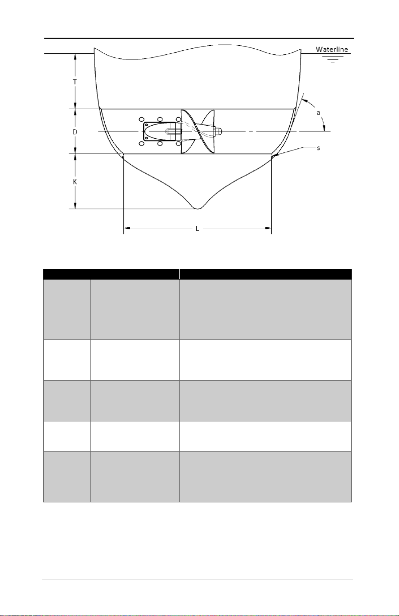
3.1 Tunnel Thruster Location Selection and Installation................................................ 8
3.2 Transom Mounted Thruster Location and Installation........................................... 15
3.3 Lubricating Oil System............................................................................................ 19
4Maintenance and Service....................................................................................... 20
4.1 Preventative Maintenance..................................................................................... 20
4.2 Recommended Spare Parts.................................................................................... 20
4.3 Propeller Installation and Removal........................................................................ 21
4.4 Transom Mount Thruster Tube Removal and Installation...................................... 22
4.5 Setting Coupling Distance ...................................................................................... 24
4.6 Bearing Cap Removal & Oil Drain........................................................................... 24
4.7 Oil Changes ............................................................................................................ 25
4.8 Shaft Seal Replacement ......................................................................................... 26
5Hydraulics.............................................................................................................. 27
5.1 System Requirements ............................................................................................ 27
5.2 Installation ............................................................................................................. 27
6Parts Lists .............................................................................................................. 29
6.1 KP12 Tunnel Thrusters ........................................................................................... 29
6.2 KP14 Tunnel Thrusters ........................................................................................... 31
6.3 KP12 Bolt-On Thrusters.......................................................................................... 33
6.4 Leg Subassembly.................................................................................................... 35
6.5 Shaft Subassembly................................................................................................. 37
6.6 Accessories............................................................................................................. 38
6.7 Parts Lists Notes..................................................................................................... 39
7Technical Drawings................................................................................................ 41
7.1 Tunnel Thrusters.................................................................................................... 41
7.2 Transom-Mounted Hydraulic Thrusters................................................................. 43
8Warranty............................................................................................................... 44

KP12 & KP14 Hydraulic Thrusters Kobelt Manufacturing Co. Ltd
Rev A MNL-KP12X-H-TH 3 of 46
1INTRODUCTION
1.1 CONTACT
Kobelt Manufacturing Co. Ltd.
8238 129th Street
Surrey, British Columbia
Canada, V3W 0A6
Sales Tel:
Fax:
Email:
Website:
+1-604-572-3935
+1-604-590-8313
sales@kobelt.com
www.kobelt.com
This document is intended to clearly present comprehensive product data and provide
technical information to assist the end user in design applications. Kobelt reserves the right,
without notice, to change the design, or construction, of any products and to discontinue or
limit distribution of any products. Kobelt also reserves the right to change, or update, without
notice, any technical information contained within this document.
Kobelt recommends that customers visit our website to check for updates to this Manual.
Once a product has been selected for use, it should be tested by the user to ensure proper
function in all possible applications. For further instructions, please contact our distributors or
visit our website.
1.2 SAFETY
1.2.1 Safety Alerts
Throughout this manual, the following symbols, and their accompanying explanation, are
used to alert the user to special instructions concerning a service or operation that may be
hazardous if performed incorrectly or carelessly. The associated risk levels are stated below.
This symbol indicates an imminently hazardous situation which, if
not avoided, will result in death or serious injury.
This symbol indicates a potentially hazardous situation which, if not
avoided, could result in death or serious injury.
This symbol indicates a hazardous situation, which if not avoided,
could result in minor or moderate injury.
This symbol informs the reader of events not related to personal
injury but which there is a risk of damage to property or equipment.
This symbol informs the reader of safety-related instructions or
procedures.

KP12 & KP14 Hydraulic Thrusters Kobelt Manufacturing Co. Ltd
Rev A MNL-KP12X-H-TH 4 of 46
1.2.2 Notice to Installer
Disregarding the following safety measures can result in an accident causing severe injury to
personnel and damage to material assets.
•Only use the product as directed in this manual.
•Never put the product into service if there is evidence of visible damage.
•Never put the product into service before fully completing installation and
commissioning.
•Do not carry out any modifications to the product.
•Only use authentic Kobelt spare parts.
•Observe all local regulations, directives and laws during the installation of this product.
•All installation, commissioning, and maintenance work must only be conducted by
qualified personnel. (For the purpose of this manual, qualified personnel are persons
who are familiar with the assembly, installation, commissioning, and operation of the
product and who have the qualifications necessary for their occupation.)
•Observe all specifications in this manual. If these guidelines are not followed and
damage occurs, the warranty will be voided.
1.2.3 Product Hazards
The rotating components of the thruster can generate forces that
can cause pinch or crush injuries. Keep body parts clear of the
thruster when it is operating. Lock out any power sources before
working on the thruster.
Exercise safety precautions pertaining to hydraulics including:
•Wearing safety glasses.
•Exhausting pressure and locking out the pressure source.
•Being qualified to work on hydraulics.
On standard thruster installations, the mounting saddle installation
to the tube should be considered permanent once installed and
should not be removed. The leg and propeller assemblies can simply
be detached from the saddle when service is required. This ensures
the saddle stays sealed and correctly aligned eliminating the need
for propeller realignment or saddle resealing.
On transom mounted thruster installations, the mounting plate and
saddle installation should be considered permanent once installed
and should not be removed. The thruster leg assembly and tube can
simply be detached from the rest of the installation when service is
needed allowing the mounting plate installation to remain sealed.
To help prevent corrosion, it is strongly recommended to connect
the thruster to the vessel’s existing bonding system. Consult a
marine electrical specialist for advice regarding modifying your
vessel’s bonding system.

KP12 & KP14 Hydraulic Thrusters Kobelt Manufacturing Co. Ltd
Rev A MNL-KP12X-H-TH 5 of 46
2PRODUCT DESCRIPTION
2.1 OVERVIEW
The figure below shows a typical tunnel thruster with all of its major components identified.
Thrusters are meant to assist in docking, station keeping and maneuvering in tight spaces and
are usually installed to an athwartships tunnel that goes through the vessel’s hull (tunnel
thrusters). Some thruster models are also offered in bolt-on versions which do not attach to a
tunnel but instead mount externally to the transom of a vessel. Thrusters are powered by a
hydraulic motor which is mounted to the thruster saddle. The direction of thrust can be
changed by reversing the direction of oil flow to the hydraulic motor. All thrusters are
available in aluminum or bronze versions.
Figure 1 –Names of thruster components

KP12 & KP14 Hydraulic Thrusters Kobelt Manufacturing Co. Ltd
Rev A MNL-KP12X-H-TH 6 of 46
2.2 MODEL CODE KEY
2.3 TECHNICAL DATA
Your authorized Kobelt distributor typically will also sell you a hydraulic motor that is most
compatible with your vessel’s existing hydraulic system. Given that there is no “standard”
motor, pressure and flow requirements do not depend solely on the thruster model used and
will vary from installation to installation. Table 1 below provides examples of possible
operating parameters for typical installations. Note that operating parameters are also
affected by the vessel’s hull and tunnel geometry.
Table 1 - Hydraulic motor operating specifications
Model
Flow
Pressure
Power
KP 12
18 gpm
68 lpm
2,300 psi
172 bar
25 hp
18 kW
KP 12 HD
20 gpm
76 lpm
2,600 psi
179 bar
31 hp
23 kW
KP 14
24.5 gpm
93 lpm
2,600 psi
179 bar
38 hp
28 kW

KP12 & KP14 Hydraulic Thrusters Kobelt Manufacturing Co. Ltd
Rev A MNL-KP12X-H-TH 7 of 46
2.4 PARTS
Detailed parts lists can be found in section 6 of this manual. You should find the following
items when you receive your Keypower thruster:
•A completely assembled thruster which consists of
oHydraulic motor (sold separately)
1
oSaddle
oLeg subassembly
oPropeller
oProp nut
oMounting plate (bolt-on transom thrusters only)
oFibreglass tube (bolt-on transom thrusters only)
•Prop puller tool
•Header tank and its mounting hardware
•Installation bolt kit (tunnel thrusters only)
•Template for thruster tube cut (tunnel thrusters only)
•Backing plate (bolt-on transom thrusters only)
•This manual
Kobelt can supply fibreglass, steel and aluminum tubes for your thruster if needed. If
supplying your own tube, be aware that the wall thickness must be correct for proper
alignment of the thruster; you may be required to build up to the thruster saddle for thinner
tubes. Refer to the table below for the required tube dimensions of each thruster size.
Table 2 –Thruster tube dimensions
Model
Tube ID
[inches]
Wall Thickness
[inches]
KP12 & KP12 HD
12
3/8
KP14
14
3/8
1
Prior to commencing thruster installation, you should note down the make and model of
the motor that has been supplied with your thruster on the space provided on page 1.

KP12 & KP14 Hydraulic Thrusters Kobelt Manufacturing Co. Ltd
Rev A MNL-KP12X-H-TH 8 of 46
3INSTALLATION AND LOCATION SELECTION
This section has been prepared to assist the owner and the installer in understanding the
installation of the thruster to the vessel. All work should be performed by a professional who
is competent in marine mechanical installations.
Installation of the thruster involves cutting into the hull of the vessel
and improper material use or workmanship can result in property
damage, and/or a loss of performance.
Care should be taken when selecting a location for the thruster installation as it can greatly
affect the performance of the thruster. A thruster is a low-pressure axial pump whose
performance is sensitive to the interference of the influx of water to the propeller and the
pressure distribution outside of the vessel’s hull. Additionally, the thruster installation can
increase the drag of the vessel if due care is not taken in selecting its location. For the reasons
mentioned, special consideration must be given so that a hydrodynamically favourable and
economically sensible installation is achieved. If the guidelines in this manual are not taken
into consideration, then a loss of thrust should be expected. Best results can be achieved by
consulting with a naval architect familiar with the vessel.
3.1 TUNNEL THRUSTER LOCATION SELECTION AND INSTALLATION
This section describes the installation of the tunnel and thruster to your vessel. You can
either:
•Install the tube to the hull first, and then install the thruster to the tube.
•Make the leg cut out and mounting holes first (steps 1 to 6 in section 3.1.4 on page
13), install the tube to the vessel, then complete the installation by sealing the
thruster to the tube (remaining steps in section 3.1.4).
Note that the following instructions are for tunnel installations only (installing to an
athwartships tunnel through the vessel’s hull), see section 3.2 on page 15 for bolt-on
transom-mounted thruster installation instructions.
3.1.1 Locating the Thruster on Your Vessel
Consider the following when selecting a location to install the thruster:
•Locating the thruster as far forward in the vessel will maximize its effectiveness.
•The propeller’s midline should be located as close to the centreline of the vessel as
possible. The provided cutting template has the propeller midline location marked
on it which will allow you to accurately locate the propeller midline.
•Account for the space the saddle, motor, and any hydraulic fittings and hoses will
take up within the vessel. See section 7.1 on page 41 for the thruster’s dimensions.
•The thruster can be installed so that the drive components are above the tube,
horizontal to the tube or at any angle in between.
•No parts of the thruster are to extend outside of the hull.
•The tunnel’s length, vertical positioning, and opening shape all greatly affect
thruster performance. Refer to Figure 2 on page 9 and accompanying Table 3 for
definitions of these parameters and their recommended values.

KP12 & KP14 Hydraulic Thrusters Kobelt Manufacturing Co. Ltd
Rev A MNL-KP12X-H-TH 9 of 46
Figure 2 –Thruster tunnel location parameters that affect performance
Table 3 –Recommendations for thruster tunnel location.
Dimension
Recommendation
Consequence if recommendation not met
T
•T ≥D*
•T = 1.5D is best
•Insufficient depth can cause air suction
which reduces thrust, increases noise and
vibration, and can damage the thruster.
•Note that excessive depth can be
inefficient and cause excessive roll of the
vessel during thruster operation.
L
•L ≥ 2D
•L ≤ 6D
•Insufficient length does not allow the flow
to stabilize thus decreasing thrust.
•Excessive length increases flow resistance
thus decreasing thrust.
K
•If L < 3D, then
K ≥D/2
•If L ≥ 3D, then
K ≥ D/4
•Circular currents can develop below the
hull of the ship which decrease thrust.
a
•Close to 90°as
possible
•Greater hull inclination results in decreased
thrust (for this reason a bulbous bow
makes an excellent location for a thruster).
S
•S ≥ 0.10D
•S ≤ 0.15D
•Cone (good) or
radius (better)
•Insufficient tunnel fairing causes incoming
water to be excessively turbulent
decreasing thrust.
•Excessive fairing will increase the hull drag
during normal ahead travel.
*Note this dimension applies to the lightest waterline. Vessels used in open seas must also
consider the effects of pitch, roll and wave action on the submersion of the thruster.

KP12 & KP14 Hydraulic Thrusters Kobelt Manufacturing Co. Ltd
Rev A MNL-KP12X-H-TH 10 of 46
3.1.2 Protective Grid
Grids are often fitted to thruster installations with the intent of reducing the drag created by
the tunnel opening and to prevent the ingression of objects that could potentially damage the
thruster. Kobelt recommends consulting with a naval architect to design the protective grid as
the optimum design will depend greatly on the shape and operating conditions of your vessel.
It is recommended to consult with a naval architect/shipyard to
design a protective grid. The optimum grid design depends highly on
the specifics of your vessel. A poorly designed grid can cause a large
decrease in thruster performance.
If it is not possible to consult with a professional regarding the design of a protective grid but
it is still desired to have one, follow the instructions below for a general installation that will
achieve satisfactory performance at best.
•The grid should be made up of two to four equally spaced parallel bars which are
interconnected by one perpendicular bar across the centre of the parallel bars
(see Figure 4 below).
•Elliptical bars will result in the best performance. Rectangular bars should also
result in acceptable performance if cost is a concern. Round and square bars are
not recommended under any circumstances as they generally perform poorly.
•The bars should not cover more that 10% of the tunnel area.
•Mount the grid behind the induction cone/radius (see Figure 3 below).
Figure 3 –Recommended location of protective grid
•Angle the parallel bars so they are aligned perpendicular to the flow of water
over the hull of the bow in the location of the tunnel (left image in Figure 4). The
flow of the water of the hull is typically determined from model tests. If the
direction of the flow is not known, mounting the bars 15°relative to the
waterline could result in satisfactory performance (right image in Figure 4).
Figure 4 –Orientation of protective grid relative to vessel

KP12 & KP14 Hydraulic Thrusters Kobelt Manufacturing Co. Ltd
Rev A MNL-KP12X-H-TH 11 of 46
3.1.3 Installation of Fibreglass Thruster Tubes
This section has been prepared to assist the owner and installer in understanding the
installation of fibreglass thruster tubes. All work should be done by a professional who is
competent in marine mechanical installations. The tube can be installed after or before the
leg cut-outs and mounting holes have been made (steps 1 to 6 in section 3.1.4 on page 13
instruct how to make the cut out and mounting holes).
1. Determine a suitable location for the thruster using the guidelines described in
3.1.1 Locating the Thruster on Your Vessel.
2. Cut a hole in the hull large enough in diameter to allow for a fairing with a
minimum radius as specified in Table 3 on page 9.
3. Cut the tube to length so that it fits in between the holes cut in the hull. Allow for
a gap between the tube and hull for the radius. If the mounting holes and cut-out
have already been made, then you must also ensure that the tube length is cut so
that the propeller midline is centred as much a possible athwartships.
4. Move the tube to the desired position in the vessel and fix it in place.
5. Fibreglass the tube in place. Fibreglass must cover the entirety of the tube
exterior except in the area the saddle will mount to. Fibreglass thickness should
be in accordance to the applicable marine standards for the vessel. Refer to
Figure 5 on page 12 for an example of a fibreglass tunnel installation.
Under no circumstances should fibreglass be applied to the area of
the tube which contacts the underside of the saddle. Any additional
thickness in the area of the flange will adversely affect the fit of the
thruster assembly.

KP12 & KP14 Hydraulic Thrusters Kobelt Manufacturing Co. Ltd
Rev A MNL-KP12X-H-TH 12 of 46
Figure 5 –Thruster tube fibreglassing example

KP12 & KP14 Hydraulic Thrusters Kobelt Manufacturing Co. Ltd
Rev A MNL-KP12X-H-TH 13 of 46
3.1.4 Installing the Thruster to the Tube
This section has been prepared to assist the owner and installer in understanding the
installation of the thruster to the tube. All work should be performed by a professional who is
competent in marine mechanical installations. The thruster can be installed to the tube
before or after the tube has been installed to the hull.
1. Use the provided cutting template to cut the required opening in the tube
2
. Note
that the bolt holes are not shown on the cutting template. These are added later.
2. Remove the propeller as directed by the instructions in section 4.3 Propeller
Installation and Removal on page 21 of this manual. Also, refer to that section
whenever these steps instruct you to reinstall the propeller.
3. Insert the thruster leg through the opening in the tube as shown below.
4. Reinstall the propeller and trial-fit the thruster. Check for tip clearance by using
wooden shims between the propeller blades and inner surface of the tube to
centre and position the thruster.
•Variations in tube thickness can cause the propeller to sit too close to
one side. It may be necessary to shim or grind the area on the tube
where the saddle sits.
5. With the thruster properly aligned, match drill six 3/8”holes with the existing
saddle mounting holes through the tube.
6. Remove the propeller from the thruster assembly and remove the thruster
assembly from the tube, then:
•Metal tubes: File the holes in the tube so that they are square-shaped.
•Fibreglass tubes: Increase the size of the holes in the tube to 31/64”
2
The cutting template can also be downloaded from www.kobelt.com on the KP12 product
page.

KP12 & KP14 Hydraulic Thrusters Kobelt Manufacturing Co. Ltd
Rev A MNL-KP12X-H-TH 14 of 46
7. At this point it is recommended to apply a marine barrier coat and antifouling
paint to the thruster tunnel. The following sub-steps will guide you through that
process:
1. Obtain marine barrier epoxy and antifouling paint that is appropriate
for the operating environment of the vessel.
2. Apply the epoxy barrier coat to the inner diameter of the thruster tube.
Refer to the information provided by the epoxy manufacturer for
application procedures, recommended thickness, and drying time.
3. Apply the antifouling paint to the inner diameter of the thruster tube.
Refer to the information provided by the paint manufacturer for
application procedures, recommended thickness, and drying time.
Paint and coatings can be applied to the thruster as well, however,
nothing should be applied to the zinc anode or the surface on
which the anode mounts to.
8. Apply a generous amount of 3M 5200 marine adhesive sealant (standard or fast
cure) on the surfaces where the bottom of the saddle and tube contact each other
and the 6x mounting holes. Reinsert the thruster assembly onto the tube. Apply a
liberal amount of 3M 5200 to the provided mounting bolt kit fasteners and secure
the thruster to the tube (hand tight). Make sure to follow any gap size limits stated
in the instructions that are provided with the sealant. See image below for
fastener orientation.
9. Reinstall the propeller. Check for tip clearance by using wooden shims between
the propeller blades and the inner surface of the tube to centre and position the
thruster.
10. Tighten the 6 mounting nuts to 5-10 lbf·ft and remove the shims. Allow for the
sealant to cure (refer to the instructions provided with the sealant for cure time).
11. After the sealant has cured, torque the 6 nuts to 20-25 lbf·ft. The mechanical
installation of the thruster to the tube is now complete. Note down the make and
model of the hydraulic motor on page 1 of this manual if you have not done so
already.

KP12 & KP14 Hydraulic Thrusters Kobelt Manufacturing Co. Ltd
Rev A MNL-KP12X-H-TH 15 of 46
3.2 TRANSOM MOUNTED THRUSTER LOCATION AND INSTALLATION
3.2.1 Locating the Transom Mounted Thruster on your Vessel
Consider the following when selecting a location to install the thruster:
•The tube should be centred about the centreline of the vessel as much as
possible.
3
•Account for the space the backing plate, motor, and any hydraulic fittings and
hoses will take up within the vessel. See Figure 24 on page 43 for the thruster’s
dimensions.
•Insufficient submersion can cause air to be sucked into the thruster tube which
can result in excessive noise and vibration, decreased thrust, and damage to the
thruster. The top of the tube should be at least one tunnel diameter deep from the
lightest waterline (i.e., T should be greater than D in Figure 6). For vessels
operating in open seas an allowance for pitch, roll, and wave action should be
added to the minimum submersion recommendation.
•Submerging the thruster too deep to where the tube extends past the bottom
edge of the transom is permissible but can cause increased drag during regular
ahead travel.
•The transom needs to be flat at the location the thruster mounting plate will be
fixed to. Curved surfaces may cause the seal between the mounting plate and hull
to fail causing an ingress of water into the vessel.
If you find it challenging to fit the standard tube offering to your vessel, please contact Kobelt
Manufacturing and we will try to come up with a custom solution that will work for you.
Figure 6 –Transom mounted thruster submersion recommendation
3
If having to choose between sufficient submersion or centering the tube athwartships, the
installation location that ensures more submersion should be used.

KP12 & KP14 Hydraulic Thrusters Kobelt Manufacturing Co. Ltd
Rev A MNL-KP12X-H-TH 16 of 46
3.2.2 Tube Preparation
It is recommended to apply a marine barrier coat and antifouling paint to the tube before
installing the thruster to the transom. The steps below will guide you through that process.
Paint and coatings can be applied to the thruster as well, however,
nothing should be applied to the zinc anode or the surface to
which the anode mounts to.
1. Remove the tube as described in section 4.4 on page 22.
2. Obtain marine barrier epoxy and antifouling paint that is appropriate for the
operating environment of the vessel.
3. Apply the epoxy barrier coat to the entirety of the thruster tube. Refer to the
information provided by the epoxy manufacturer for application procedures,
recommended thickness, and drying time.
4. Apply the antifouling paint to the entirety of the thruster tube. Refer to the
information provided by the paint manufacturer for application procedures,
recommended thickness, and drying time.
5. Reinstall the tube as described in section 4.4 on page 22.
3.2.3 Cutting the Transom
This section instructs how to install transom-mounted thrusters. All work should be done by a
professional who is competent in marine mechanical installations. It is recommended to prep
the tube as per instructions in the previous section prior to installing the thruster.
When a suitable location has been selected (section 3.2.1 on page 15) for the thruster
proceed with the next steps to cut the opening in the transom.
1. Place the thruster backing plate at the desired location and trace the central
opening (see Figure 7 on the next page).
2. Remove the plate and cut the transom in the shape of the trace made in step 1.
3. Note that in the case of cored fibreglass hulls a modification must be made. For
hull core materials that are soft and cannot withstand the clamping load of the
backing and mounting plates, material must be removed from the core and
internal hull so that the backing plate can be mounted directly to the external hull.
If it is known that the core is strong and firm enough, then the mounting holes can
be drilled directly through the core and internal hull (next step) and the backing
plate can be mounted directly to the internal hull. In either case, new fibreglass
should be laid down to seal-off any exposed hull core. See Figure 8 on the
following page for a depiction of this modification.
4. From outside the vessel, fit the thruster-tube assembly through the newly cut hole
and from inside the vessel fit the backing plate over the motor. When the
placement is satisfactory, remove the thruster and match drill 33/64” size holes
through the 14 mounting holes in the backing plate.

KP12 & KP14 Hydraulic Thrusters Kobelt Manufacturing Co. Ltd
Rev A MNL-KP12X-H-TH 17 of 46
Figure 7 –Backing plate for transom-mounted thrusters
Figure 8 –Installation of transom-mounted thrusters to cored fibreglass hulls

KP12 & KP14 Hydraulic Thrusters Kobelt Manufacturing Co. Ltd
Rev A MNL-KP12X-H-TH 18 of 46
3.2.4 Installing the Thruster to the Transom
This section has been prepared to assist the owner and installer in understanding the
installation of transom-mounted thrusters. All work should be performed by a professional
who is competent in marine mechanical installations.
1. Figure 9 illustrates this step. Carry out a dry installation to ensure that the
mounting plates and thruster assembly properly fit together on the transom. The
mounting plate is already bolted and sealed to the thruster assembly. From the
outside of the hull, fit the motor end of the thruster through the central opening
with the mounting plate placed against the transom. Fit the backing plate over the
motor from the inside of the hull, sandwiching the transom between the two
plates. Fasten this into place with 3/8” fasteners (316 stainless steel is
recommended). Once the dry installation has yielded satisfactory results (plate lies
flat on transom and there is no interference with other vessel components)
remove the thruster from the transom and continue to next step.
Figure 9 - Thruster fitted onto transom
2. Repeat step 1, but this time apply 3M™ 5200 (regular or fast cure) marine adhesive
sealant between the mount plate and the vessel’s hull, the fasteners used to
fasten the thruster to the transom, and the mounting holes. Refer to the
instructions provided with the sealant for information regarding gap size limits and
cure time. At this point the mechanical installation of the thruster to the vessel can
be regarded as complete. Note down the make and model of the hydraulic motor
on page 1 of this manual if you have not done so already.

KP12 & KP14 Hydraulic Thrusters Kobelt Manufacturing Co. Ltd
Rev A MNL-KP12X-H-TH 19 of 46
3.3 LUBRICATING OIL SYSTEM
The thruster needs to be connected to a source of oil to provide lubrication to the gears,
bearings, and seals. This can be achieved by either connecting the thruster to an elevated
header tank (section 3.3.1) or pumping oil through the thruster assembly (section 3.3.2).
3.3.1 Header Tank Location and Oil Fill Instructions
The distance between the bottom of the header tank and the centreline of the thruster
should be at least 1.25 times the distance between the heaviest water line and the centreline
of the thruster (see figure below); this ensures there is positive pressure within the thruster
that prevents the ingress of seawater should a seal failure occur. As shown in the figure, the
header tank should be connected to the port that is inline with the tube axis. Continue from
step 2 in the instructions in section 4.7.1 on page 25 to complete the oil fill for the thruster.
Figure 10 - Required elevation of header tank over the waterline
3.3.2 Circulating Oil Method
Instead of connecting the thruster to a header tank it can be connected to a pump that
circulates oil through the thruster. This lubrication method is recommended for station-
keeping and other severe commercial applications. In this case, the header tank connection in
Figure 10 above should be replaced with a return line to the lube reservoir. Either of the
remaining ports on the side of the saddle can be used to connect to the pressure source.
Kobelt manufactures a pump (part number: KP426-B) specifically designed for this application
that is available for purchase. Use SAE75W-90 synthetic gear oil.
This manual suits for next models
1
Table of contents