Contents
4-3-4-3-9 List of output data��������������������������������� 35
4-3-4-3-10 Details of output data�������������������������� 36
4-3-4-3-11 List of output signals ��������������������������� 41
4-3-4-3-12 Details of output signals ��������������������� 41
4-3-5 Timing chart ������������������������������������������������ 43
4-3-5-1 Timing charts for EW2C-H-NP, EW2C-H-
PN, and EW2C-H-CC ������������������������������ 43
4-3-5-2 Timing charts for EW2C-H-CCD�������������� 45
4-4 Actuator number setting�������������������������������������������� 58
4-5 Point data specications������������������������������������������� 58
4-6 How to use the size detecting function
4-6-1 When using an actual workpiece for size
detecting range setting�������������������������������� 60
4-6-2 When using direct input for size detecting
function setting �������������������������������������������� 60
4-7 Communication
4-7-1 Communication parameter specications���� 61
4-7-2 Communication cable���������������������������������� 61
4-7-3 Addresses���������������������������������������������������� 61
4-7-4 Communication commands������������������������� 61
4-7-5 List of communication commands ��������������� 62
4-7-6 Details of communication commands���������� 63
4-8 Parameters
4-8-1 Parameter setting method��������������������������� 69
4-8-2 Explanation of parameters �������������������������� 70
4-9 List of errors ������������������������������������������������������������� 72
4-10 Easy mode���������������������������������������������������������������74
4-10-1 I/O connector signal table for easy mode���74
4-10-2 Details of input signals for easy mode �������74
4-10-3 Details of output signals for easy mode ���� 75
4-10-4 Parameters������������������������������������������������ 76
4-10-5 Time charts ����������������������������������������������� 77
Chapter 5 Troubleshooting
5-1 If a problem occurs ��������������������������������������������������� 80
5-2 Countermeasures for alarms������������������������������������ 80
5-3 Alarm specications ������������������������������������������������� 80
5-3-1 List of alarms ���������������������������������������������� 81
Chapter 6 Specications
6-1 Basic specications of main unit ������������������������������ 82
6-2 Basic specications of the controller ������������������������ 83
Chapter 7 Outline Drawings
7-1 Main unit outline drawings ���������������������������������������� 88
7-2 Controller outline drawings ��������������������������������������104
7-3 Outline drawings for additional parts (Unit: mm)������105
Chapter 8 Technical Data
8-1 Accuracy������������������������������������������������������������������108
8-2 Allowable moment ���������������������������������������������������108
8-3 Displacement angle of the table in relation to bending
moment �������������������������������������������������������������������109
8-4 Thrust ����������������������������������������������������������������������110
- 1 -
Chapter 1 Safety Precautions
1-1 Safety�������������������������������������������������������������������������� 2
1-2 Precautions ����������������������������������������������������������������� 2
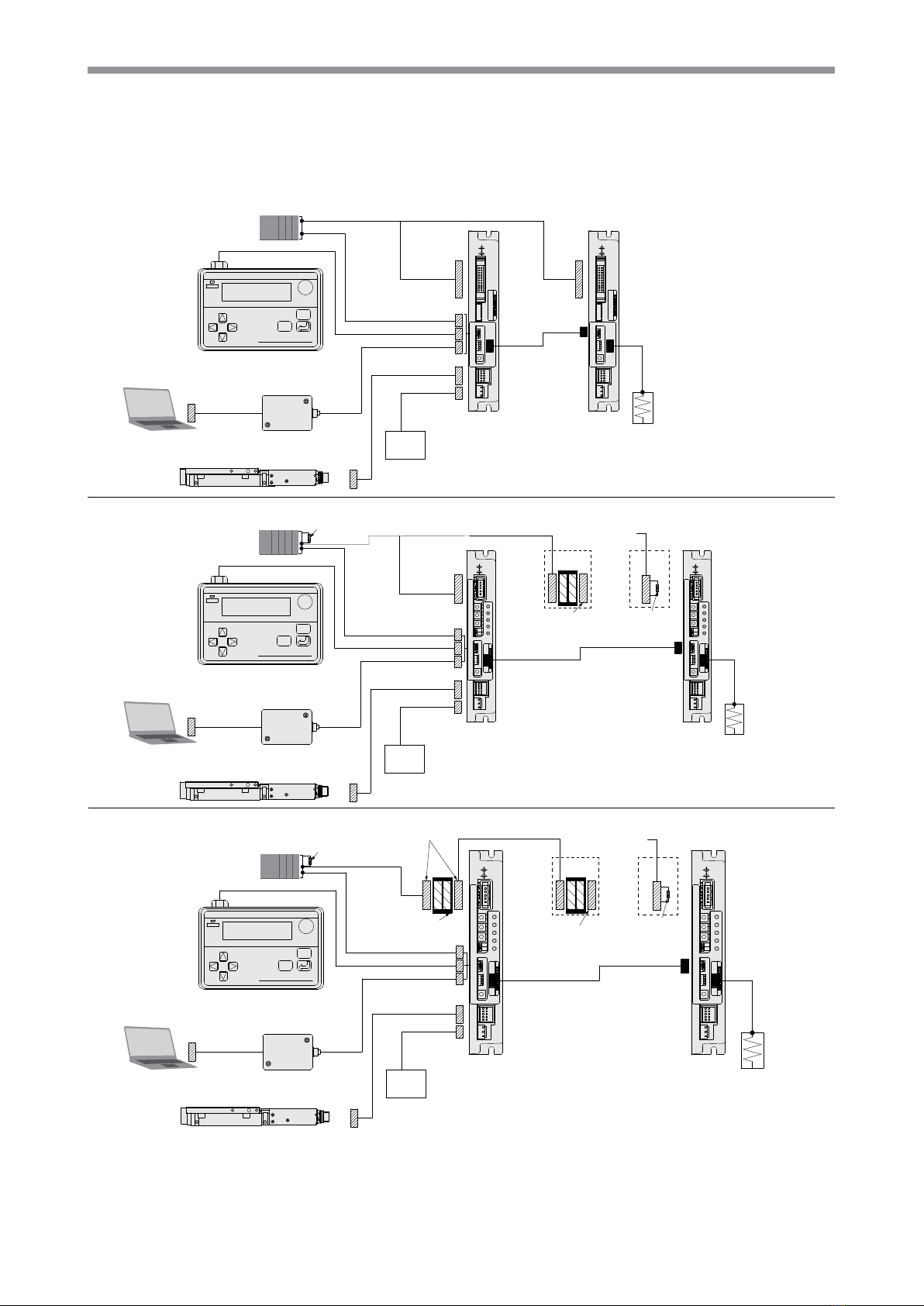
Chapter 2 System Conguration
2-1 Entire system conguration ���������������������������������������� 3
2-2 Options and accessories�������������������������������������������� 4
2-3 Setting up for operation ���������������������������������������������� 5
Chapter 3 Main Unit
3-1 Handling the main unit
3-1-1 Precautions���������������������������������������������������� 6
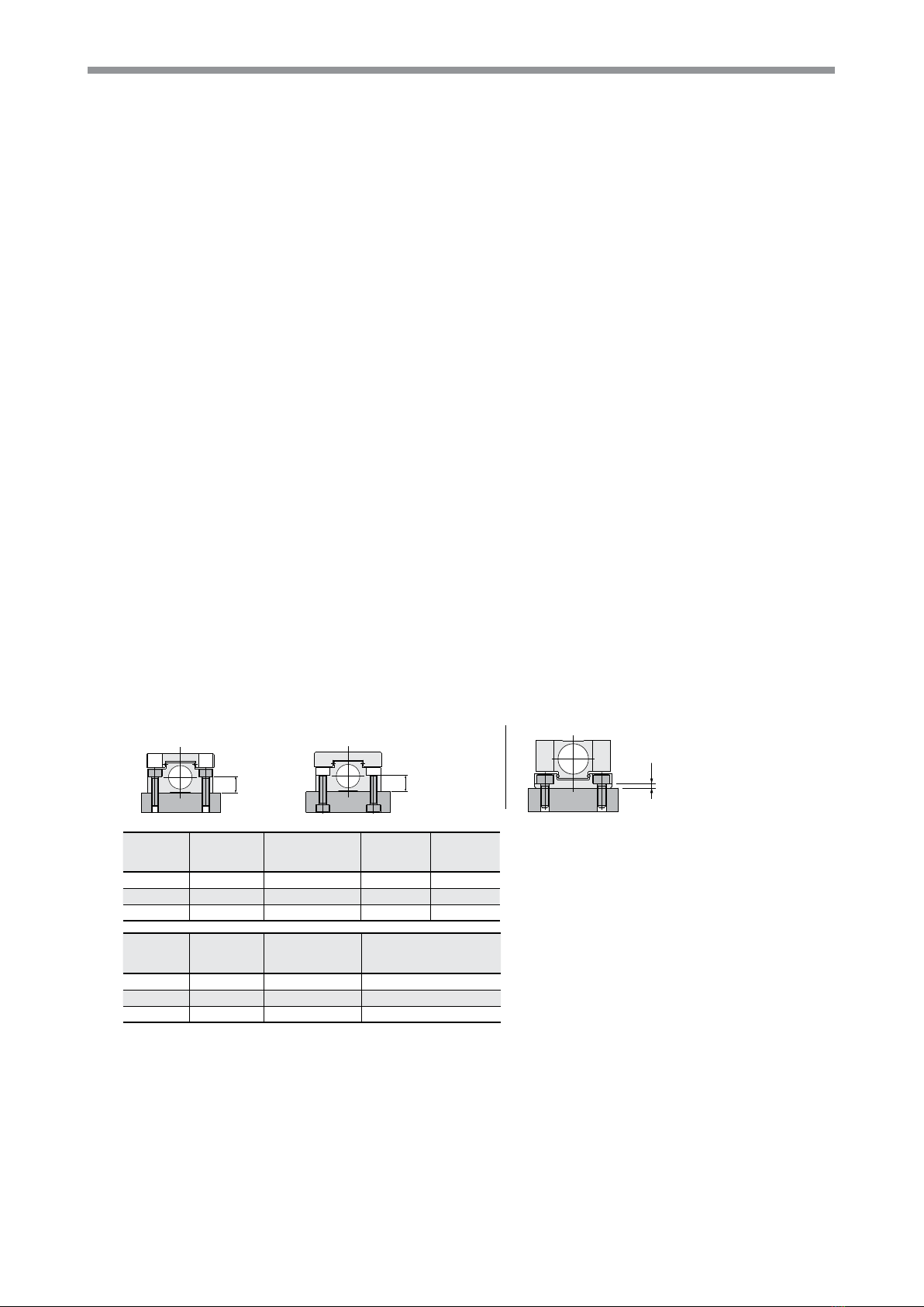
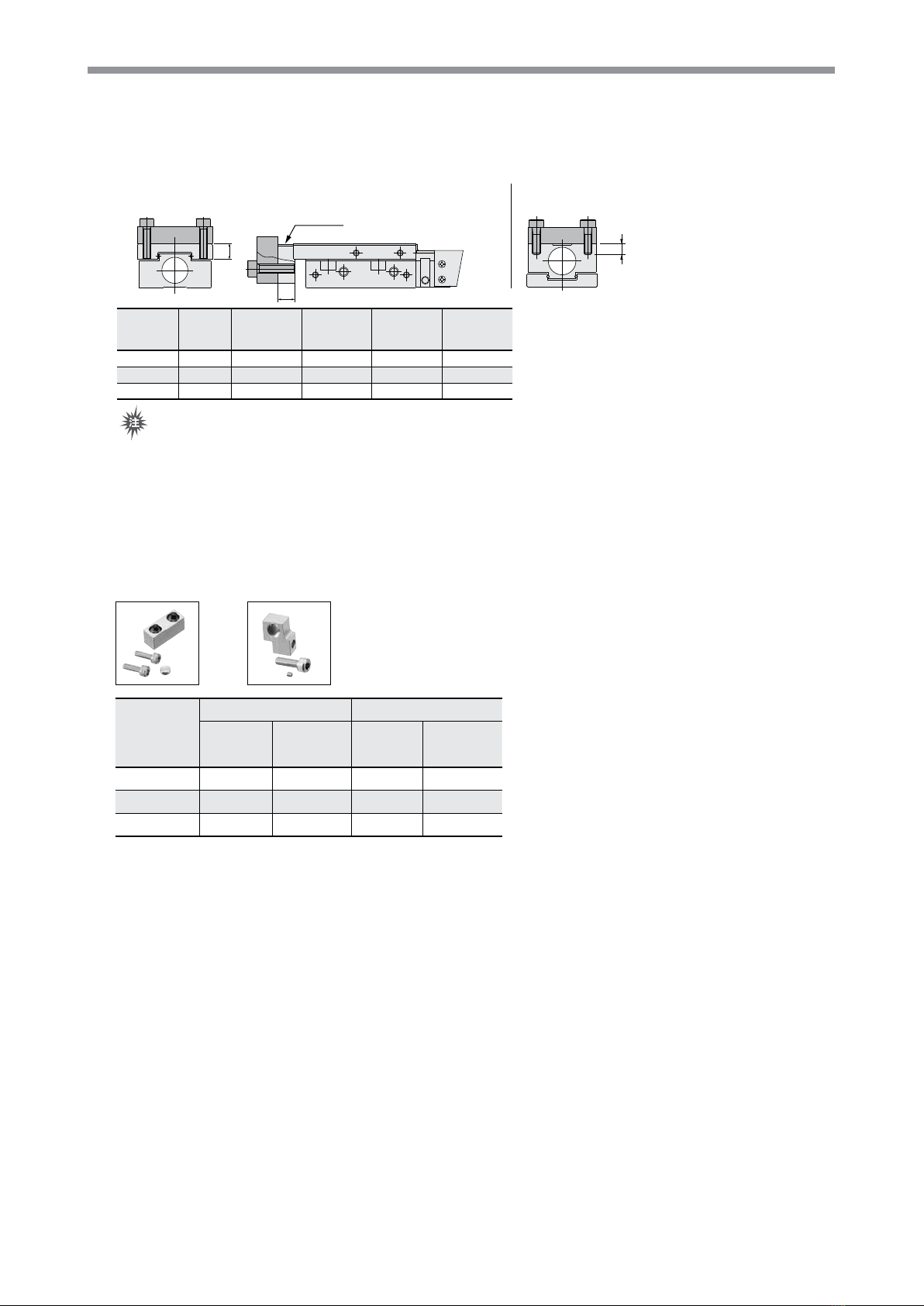
3-2 Mounting
3-2-1 Mounting the product ������������������������������������ 7
3-2-2 Mounting a workpiece����������������������������������� 8
3-2-3 Mounting the stroke adjuster������������������������� 8
Chapter 4 Controller
4-1 Appearance and functions
4-1-1 Point input type (NPN model and PNP model)
���������������������������������������������������������������������10
4-1-2 CC-Link type (remote I/O model and remote
device model) �����������������������������������������������10
4-2 Installation and connection to external devices
4-2-1 Controller installation �����������������������������������11
4-2-2 Connecting the power supply�����������������������11
4-2-3 Grounding work��������������������������������������������11
4-2-4 Wiring precautions �������������������������������������� 12
4-2-5 Connecting to the actuator�������������������������� 12
4-2-6 Connecting the I/O connector ��������������������� 12
4-3 Interface (I/O and CC-Link)
4-3-1 Connector signal tables������������������������������� 12
4-3-1-1 I/O connector signal table ������������������������ 12
4-3-1-2 CC-Link connector signal table ���������������� 12
4-3-2 Details of input signals�������������������������������� 13
4-3-3 Details of output signals������������������������������ 14
4-3-4 Input/output circuits������������������������������������� 14
4-3-4-1 I/O input/output information (point input
type controller)����������������������������������������� 14
4-3-4-2 CC-Link input/output information (CC-Link
remote I/O type controller)����������������������� 17
4-3-4-3 CC-Link input/output information (CC-Link
remote device type controller)������������������ 18
4-3-4-3-1 Lists of input/output signals and input/
output data�������������������������������������������� 21
4-3-4-3-2 One-station mode (Remote device: One
station occupied) ���������������������������������� 22
4-3-4-3-3 Two-station mode (Remote device: Two
stations occupied)��������������������������������� 23
4-3-4-3-4 Four-station mode (Remote device: Four
stations occupied)��������������������������������� 25
4-3-4-3-5 List of input data ����������������������������������� 27
4-3-4-3-6 Details of input data������������������������������ 27
4-3-4-3-7 List of input signals������������������������������� 30
4-3-4-3-8 Details of input signals�������������������������� 31