Kollmorgen Seidel digifas 7200 series User manual

Digital servo amplifier
digifas™ 7200 series
Assembly / Installation / Commissioning
Version 03/98

I General
I.1 About this manual
This manual forms part of the complete documentation for the digifas™ 7200 series of servo
amplifiers. It describes the assembly, installation and commissioning of the standard units of
this series, i.e. the versions of the servo amplifier without a CONNECT module.
It also includes advice about transport, storage, maintenance and disposal of the equipment.
Other parts of the complete documentation of the digifas™ 7200 series:
— Installation / operation instructions for the PC-operator software:
BS7200 for digifas™ 7200 series Order no. 83107
— technical description of the digital interfaces to automation systems:
BIT CONNECT for digifas™ 7200-SPS series Order no. 83108
PROFIBUS CONNECT for digifas™ 7200-L2/DP series Order no. 83106
PULSE CONNECT for digifas™ 7200-STEP series Order no. 83109
CAN CONNECT for digifas™ 7200-CAN series Order no. 83105
All the necessary documentation for the particular version of the unit is delivered together with
the servo amplifier.
This manual makes the following demands on the technical staff:
I.2 Prescribed usage of the servo amplifiers
Use the digifas™ 7200 series of servo amplifiers only on a three-phase 400V industrial earthed
mains supply to amplifier a synchronous servo-motor from the 6SM series.
The servo amplifier may only be operated in a closed switch cabinet, taking into account the
environmental requirements which are defined in Chapter I.8.1.
The digifas™ 7200 series of servo amplifiers are exclusively intended for driving the 6SM
series of brushless synchronous servo-motors under speed or torque control.
The servo amplifiers are installed as components of electrical equipment or machines and may
only be operated as integral components of such equipment.
Prepare a hazard analysis of your machine.
Chapter I General Page I - 1
digifas
®
7200 series 03.98
Transport : only by personnel with knowledge of the handling of electrostatic
sensitive devices.
Installation : only by personnel with training in electrical engineering.
Commissioning : only by personnel with extensive knowledge of the fields of
electrical engineering and amplifier technology.
Only if the system components as described in Chapter VI.2 are used and the rules for
installation in this documentation (Chapter II.1 ff) are followed, we guarantee the
confomance of the servo amplifiers with the following standards for industrial areas:
EC EMC Directive 89/336/EEC
EC Low Voltage Directive 73/23/EEC

I.8 Technical data of the digifas™ 7200 series
digifas
Rated specifications DIM 7201 7202 7204 7206
Rated supply voltage V~ 3 x 80-400 / 50...60Hz +max. 10%
Rated connected load for S1 operation kVA 0.9 1.7 2.5 3.5
Rated intermediate circuit voltage V= 560
Rated output value (rms value,
±
5%) A
rms
1.5 2.8 4.2 6
Peak output current (max. ca. 5s,
±
5%) A
rms
3,0 5.6 8.4 12
Switch-on threshold of ballast circuit V 720
Switch-off threshold of ballast circuit V 680
Pulse power of ballast circuit (max. 1s) kW 3.2 5.8
(Internal) cont. power of ballast circuit W 75 75 (140)*
Switch-off threshold on overvoltage V 750
Form factor of output current (under rated
specifications and min. load inductance) 1.01
Min. motor inductance mH 25 15 8 6
Bandwidth of subordinate current controller kHz 1
Clock frequency of output stage kHz 8.33
Residual voltage drop at rated current V 5
Quiescent power loss, output stage disabled W 15
Power loss at rated current (incl. loss in
power supply, without ballast dissipation W 33456060
Inputs
Setpoint, fixed, 14-bit resolution V
±
10
Max. common mode voltage V
±
10
Input resistance k
Ω
20
Max. input drift
µ
V/K
±
30
Digital control inputs V 12...36
mA 7
Aux. voltage supply, isolated without brake V 18...36
A1
Aux. voltage supply, isolated with brake V 24 +10/-5%
A2
max. output current brake A 1
Voltage supply option -BV- V= - 24 +10%
A - 0.1
Connections
Control signals Mini Combicon 3.81 / 12 pole, 1.5mm²
Power signals Power Combicon 7.62 / 12-pin, 2.5mm²
Resolver SubD 9-pin (socket)
PC interface SubD 9-pin (socket)
Position output ROD/SSI SubD 9-pin (plug)
digifas - STEP PULSE CONNECT Interface : Mini Combicon 3.81 / 12-pin, 1.5mm²
digifas - SPS BIT CONNECT Interface : Mini Combicon 3.81 / 12 pin, 1.5mm²
digifas - L2/DP PROFIBUS CONNECT Interface : SubD 9-pin (socket)
digifas - CAN CAN CONNECT Interface : SubD 9-pin (socket)
Option -BV- Combicon 1,5 mm²
Mechanical
Weight servo amplifier kg 2.1
Dimensions (h x w x d) servo amplifier mm 275 x 71 x 235
Weight option -BV- kg - 0,3
Dimensions (h x w x d) with option -BV- mm - 310x73x236
* >75W with option -BV- only
Chapter I General Page I - 7
digifas
®
7200 series 03.98

I.8.1 Permissible ambient conditions, ventilation, mounting position
Transport temperature/humidity
see Chapter VI.1
Storage temperature/humidity/time
see Chapter VI.1
Supply voltage tolerance
Power supply
Aux. voltage without brake
Aux. voltage with brake
Position interface supply
min. 3x80V AC / max. 3x400V AC + 10%
min. 18V DC / max. 36V DC
24V DC +10%/-5%
5V DC ± 5%
Ambient temperature at work
0 ... +45°C at rated values
+45 ... +55°C with power derating 2.5% / K
Humidity at work
relative humidity 5%... 85%, no condensation
Installation altitude
up to 1000m above mean sea level (m.s.l.) without restriction
1000...2500m above m.s.l. with power derating 1.5% / 100m
Pollution level
Pollution level 2 to EN60204 / EN50178
Protection class
IP 20
Mounting position
generally vertical (observe Chapter V.7 and V.9)
Ventilation
digifas 7201...7204 electronics and heat sink: natural convection
digifas 7206
ballast power max. 75W
ballast power 75...140W
electronics and heat sink : natural convection
forced cooling with option -BV- (see chapter V.8 and V.9)
Make sure that there is sufficient forced
circulation inside the switchgear cabinet.
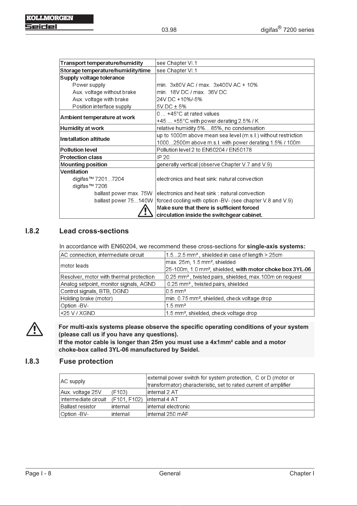
I.8.2 Lead cross-sections
In accordance with EN60204, we recommend these cross-sections for single-axis systems:
AC connection, intermediate circuit 1.5...2.5 mm² , shielded in case of length > 25cm
motor leads max. 25m, 1.5 mm², shielded
25-100m, 1.0 mm², shielded,
with motor choke box 3YL-06
Resolver, motor with thermal protection 0.25 mm² , twisted pairs, shielded, max.100m on request
Analog setpoint, monitor signals, AGND 0.25 mm² , twisted pairs, shielded
Control signals, BTB, DGND 0.5 mm²
Holding brake (motor) min. 0.75 mm², shielded, check voltage drop
Option -BV- 1.5 mm²
+25 V / XGND 1.5 mm², shielded, check voltage drop
I.8.3 Fuse protection
AC supply external power switch for system protection, C or D (motor or
transformator) characteristic, set to rated current of amplifier
Aux. voltage 25V (F103) internal 2 AT
Intermediate circuit (F101, F102) internal 4 AT
Ballast resistor internal internal electronic
Option -BV- internal internal 250 mAF
Page I - 8 General Chapter I
03.98 digifas
®
7200 series
For multi-axis systems please observe the specific operating conditions of your system
(please call us if you have any questions).
If the motor cable is longer than 25m you must use a 4x1mm² cable and a motor
choke-box called 3YL-06 manufactured by Seidel.

IV.4 Controllable torque limiting, Option -IL-
IV.4.1 General, technical data
With the -IL- option you can limit the torque of the motor which is connected to the digifas™ to a
freely selectable value which is less than the pulse torque, with the aid of a DC control voltage.
This is achieved by changing the current setpoint by means of an external analog speed-control
loop.
The electronics is contained in a separate casing.
Assembly : — on top-hat rails EN 50022-35 or C-rails, in the immediate vicinity
of the servo amplifier
Dimensions : — H x W x D (without top-hat rail) : 111 x 145 x 90 mm
Connections : — two 8-pin Combicon connectors for control signals,
setpoints and auxiliary voltages
— SubD 9-pin socket for pulse encoder signals from digifas™
— SubD 9-pin plug to transfer the pulse encoder signals to
higher-level controls
Inputs : — 2 differential amplifiers for 2 speed-setpoints ±10V = ± final speed
SW1 fixed, SW2 can be decreased by P302, both SW are added
— 1 differential amplifier for current limit 0 ... 10V
— aux. supply voltage +25V DC/ 210 mA, XGND
— enable via optocoupler, DGND
— pulse encoder signals from digifas™ , PGND
Outputs : — current setpoint ±10V, AGND
— aux. voltage +10V DC/ 5mA, AGND
— pulse encoder signal for control via optocouplers, PGND
Potentiometer : — P302 : to reduce setpoint 2 0 ... 100%
— P303 : offset (speed drift) ±10mV
— P304 : fine adjustment of speed ±12%
— P305 : AC gain (P-gain) 3 ... ∞
Solder link LB1: — open : final limit speed 3000 rev/min (standard)
— closed : final limit speed 6000 rev/min
LEDs : — display the logical state of the pulse encoder signals
Fusing : — F1, 630 mAF, to protect the aux. supply voltage
Page IV - 4 Interfaces and options Chapter IV
03.98 digifas
®
7200 series
Only possible for units without a CONNECT module.

V.10 External 5V DC power supply for the position output
Page V - 10 Drawings Chapter V
03.98 - A.4.012.4/31 digifas
®
7200 series

V.11 External 24V DC power supply for a max. of three servo amplifiers
Chapter V Drawings Page V - 11
digifas
®
7200 series 03.98 - A.4.012.4/32

V.12 External 24V DC power supply for up to 7 servo amplifiers
Page V - 12 Drawings Chapter V
03.98 - A.4.012.4/33 digifas
®
7200 series

VI Appendix
VI.1 Delivery package, transport, storage, maintenance, disposal
D elivery — 1 digifas™ 7200 series servo amplifier
package : — 3.5" diskette with the operator software BS7200
— 2 ring cores
— installation/commissioning manual for digifas™ 7200
— BS7200 operating manual
— installation/commissioning manual for the CONNECT module,
if one is built in
Transport : — only by qualified personnel
— only in the original recyclable manufacturer’s packaging
— avoid shocks
— temperature –25 ... +70°C, max. 20 K/hr variation
— humidity relative humidity max. 95% no condensation
— the servo amplifiers contain electrostatically-sensitive components
which can be damaged by incorrect handling.
Discharge yourself before you touch the servo-amplifier.
Avoid touching highly insulating materials (artificial fabrics,
plastic wrappings etc.). Place the servo amplifier on a conductive base.
— if the packaging is damaged, check the unit for visible damage. In such
a case inform the shipper and the manufacturer.
Storage : — only in the original recyclable manufacturer’s packaging
— the servo amplifiers contain electrostatically-sensitive components,
which can be damaged by incorrect handling.
Discharge yourself before you touch the servo-amplifier.
Avoid touching highly insulating materials (artificial fabrics,
plastic wrappings etc.). Place the servo amplifier on a conductive base.
— max. stacking height 10 cartons
— storage temperature –25 ... +55°C, max. 20 K/hr variation
— humidity relative humidity max. 95% no condensation
— storage duration < 1 year without restriction
> 1 year : the capacitors must be re-formed before
commissioning the servo amplifier.
To do this: remove all electrical connections,
feed the servo amplifer for about 30 min
from single-phase 230V AC on terminals L1 / L2.
Maintenance : — no maintenance required
— opening the equipment housing invalidates the guarantee
Cleaning : — if the housing is dirty : clean with isopropanol or similar
do not immerse or spray
— if there is dirt inside the unit : to be cleaned by the manufacturer
Disposal : — the servo amplfier may be reduced to its principal components (aluminium
heat sink and front panel, steel housing sections, electronics boards) by
undoing all screw connections
— the disposal should be performed by a certified disposal company.
We can give you suitable addresses.
Chapter VI Appendix Page VI - 1
digifas
®
7200 series 03.98
Other manuals for digifas 7200 series
1
This manual suits for next models
4
Table of contents
Other Kollmorgen Seidel Amplifier manuals