Kollmorgen Seidel DBL Series Parts list manual

Technical description, Installation, Setup
Edition 07/2002
File dbldbk_e.xxx
Mat.No.: 102017
Synchronous servomotors
DBL/DBK

Choose your Motor:
Already published editions
Edition Comments
04 / 2001 First edition
05 / 2001 some minor corrections
07 / 2001 some minor corrections, model number description new, name plate new, dimension drawings optimized
02 / 2002 some minor corrections, encoder dimensions added
07 / 2002 new layout, resolver connection corrected
Technical changes to improve the performance of the equipment may be made without prior notice!
Printed in the Federal Republic of Germany
All rights reserved. No part of this work may be reproduced in any form (by printing, photocopying, microfilm or any other method) or
stored, processed, copied or distributed by electronic means without the written permission of Kollmorgen Seidel Corporation.
0,5
DBL1 37 0,1..0,2
DBL2 55 0,4..0,8
DBL3 75 0,65..3
DBL4 105 2,6..9,5
DBL5 142 10,5..22
DBL6 190 22..29
DBL7 190 26..40
DBL8 240 40...115
DBK4 105 1..1,6
DBK5 142 2,1..4,3
DBK6 190 3,5..7
DBK7 190 6,5..19,5
0105020 701 30 90 130540110Nm
Type Flange Standstill torque Page
longshort
Þ22
Þ26
Þ30
Þ34
Þ38
Þ42
Þ46
Þ50
Þ54
Þ58
Þ62
Þ66

Contents Page
Contents ....................................................3
Safety Notes..................................................4
Important Notes ...............................................5
Manufacturer Declaration ........................................6
Contents
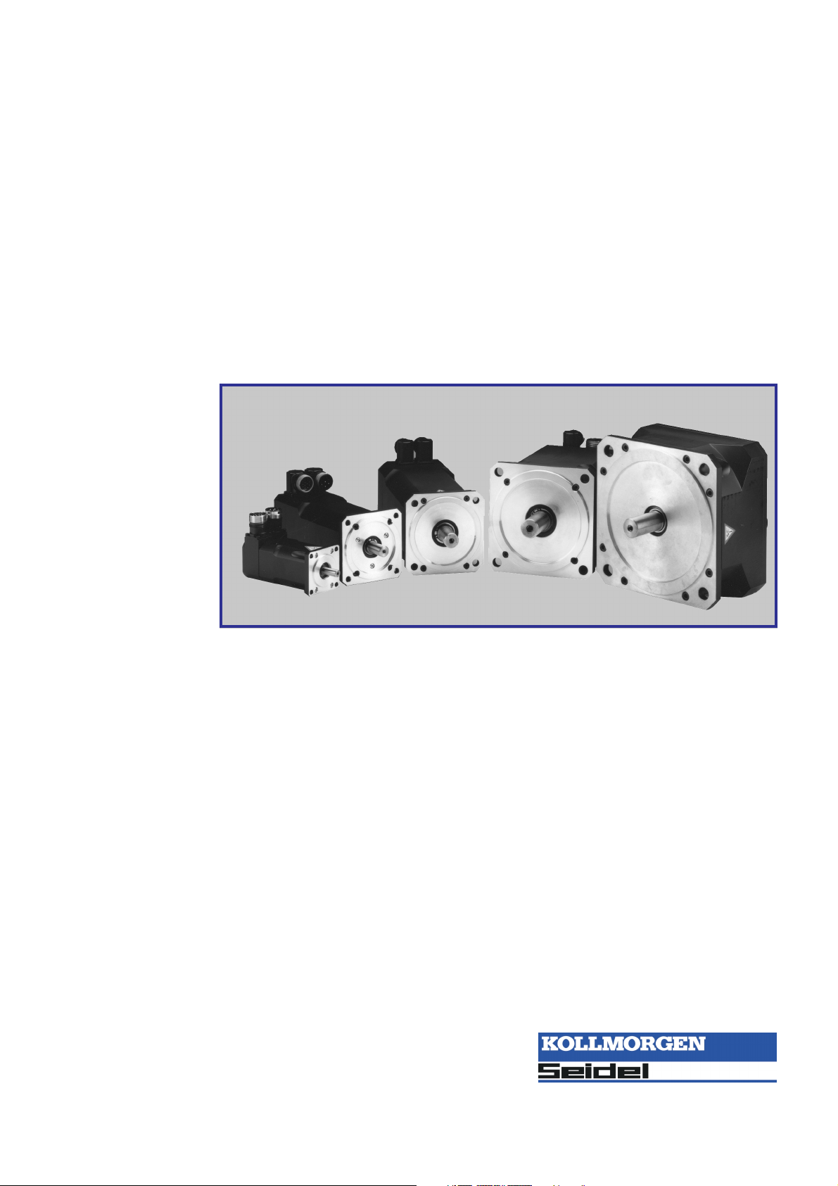
Servomotors DBL/DBK 3
Seidel 07/2002 Contents
I General
I.1 About this manual ...................................................................................7
I.2 Prescribed usage ...................................................................................7
I.3 Design of the motors.................................................................................8
I.4 General technical data ...............................................................................8
I.5 Standard features ...................................................................................9
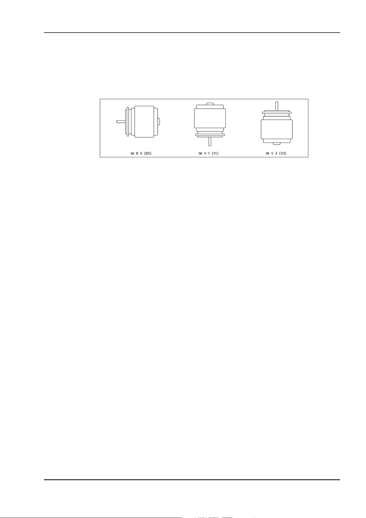
I.5.1 Style........................................................................................9
I.5.2 Shaft end, A-side ..............................................................................9
I.5.3 Flange ......................................................................................9
I.5.4 Protection class ...............................................................................9
I.5.5 Protective device ..............................................................................9
I.5.6 Insulation material class .......................................................................10
I.5.7 Vibration class ...............................................................................10
I.5.8 Connection method ...........................................................................10
I.5.9 Feedback unit ...............................................................................10
I.5.10 Holding brake ...............................................................................10
I.6 Options ..........................................................................................11
I.7 Selection criteria ...................................................................................11
I.7.1 Model number description ......................................................................12
I.7.2 Nameplate ..................................................................................12
II Installation / Setup
II.1 Important notes ....................................................................................13
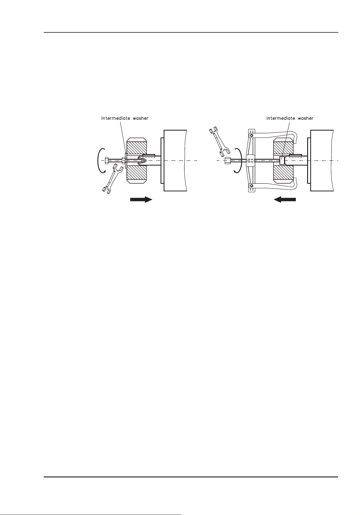
II.2 Assembly / Wiring ..................................................................................14
II.2.1 Connection of the motors ......................................................................16
II.2.1.1 Wiring diagram for resolver motors ...........................................................17
II.2.1.2 Wiring diagram for encoder motors ...........................................................18
II.3 Setup............................................................................................19
III Technical data
III.1 Definitions ........................................................................................21
III.2 DBL1 ............................................................................................22
III.3 DBL2 ............................................................................................26
III.4 DBL3 ............................................................................................30
III.5 DBL4 ............................................................................................34
III.6 DBL5 ............................................................................................38
III.7 DBL6 ............................................................................................42
III.8 DBL7 ............................................................................................46
III.9 DBL8 ............................................................................................50
III.10 DBK4............................................................................................54
III.11 DBK5............................................................................................58
III.12 DBK6............................................................................................63
III.13 DBK7............................................................................................70
IV Appendix
IV.1 Delivery package, transport, storage, maintenance, disposal ................................................73
IV.2 Removing faults ...................................................................................74
IV.3 Index ............................................................................................75

Safety Notes
lOnly properly qualified personnel are permitted to perform such tasks as
transport, assembly, setup and maintenance. Properly qualified personnel
are persons who are familiar with the transport, assembly, installation,
setup and operation of motors, and who have the appropriate qualifications
for their jobs. The qualified personnel must know and observe the following
standards and regulations:
IEC 364 resp. CENELEC HD 384 or DIN VDE 0100
IEC-report 664 or DIN VDE 0110
national regulations for safety and accident prevention or BGV A2
lRead the available documentation before assembly and setup. Incorrect
handling of the motors can result in injury and damage to persons and
machinery. Keep strictly to the technical data and the information on the
connection requirements (nameplate and documentation).
lThe manufacturer of the machine must generate a hazard analysis for the
machine, and take appropriate measures to ensure that unforeseen
movements cannot cause injury or damage to any person or property.
lIt is vital that you ensure that the motor housing is safely earthed to the
PE(protective earth) busbar in the switch cabinet. Electrical safety is
impossible without a low-resistance earth connection.
lDo not unplug any connectors during operation. This creates the danger of
death, severe injury, or extensive material damage.
lPower connections may be live even when the motor is not rotating. Never
disconnect the power connections of the motor while the equipment is
energised. This can cause flashovers with resulting injuries to persons and
damage to the contacts.
lAfter disconnecting the servoamplifier from the supply voltage, wait at least
five minutes before touching any components which are normally live (e.g.
contacts, screw connections) or opening any connections.
The capacitors in the servoamplifier can still carry a dangerous voltage up
to five minutes after switching off the supply voltages. To be quite safe,
measure the DC-link voltage and wait until the voltage has fallen below 40V.
lThe surfaces of the motors can be very hot in operation, according to their
protection category. The surface temperature can reach 100°C. Measure the
temperature, and wait until the motor has cooled down below 40°C before
touching it.
lRemove any fitted key (if present) from the shaft before letting the motor run
independently, to avoid the dangerous results of the key being thrown out
by centrifugal forces.
Symbols used in this manual:
Danger to personnel from electricity
and its effects
General warning
general instruction
mechanical hazard
Þsee chapter (cross reference) lspecial emphasis
Safety notes / Symbols
4 Servomotors DBL/DBK
Safety notes / Symbols 07/2002 Seidel

Important Notes
lServomotors are precision equipment. The flange and shaft are especially
vulnerable during storage and assembly — so avoid brute force. Precision
requires delicacy. It is important to use the locking thread which is provided
to tighten up couplings, gear wheels or pulley wheels and warm up the drive
components, where possible. Blows or the use of force will lead to damage
to the bearings and the shaft.
lWherever possible, use only backlash-free, frictionally-locking collets or
couplings, e.g. from the manufacturers Baumann & Cie, Gerwah, Jacob, KTR
or Ringspann. Ensure correct alignment of the couplings. A displacement
will cause unacceptable vibration and the destruction of the bearings and
the coupling.
lFor toothed belts, it is vital to observe the permissible radial forces. An
excessive radial load on the shaft will significantly shorten the life of the
motor.
lAvoid axial loads on the motor shaft, as far as possible. Axial loading
significantly shortens the life of the motor.
lIn all cases, do not create a mechanically constrained motor shaft mounting
by using a rigid coupling with additional external bearings (e.g. in a
gearbox).
lFor mounting style V3 (shaft end upwards), make sure that no liquid can
enter the upper bearing.
lTake note of the no. of motor poles (6-pole) and the no. of resolver poles
(2-pole), and ensure that the correct setting is made in the servoamplifier
which is used. An incorrect setting can lead to the destruction of the motor,
especially with small motors.
Important notes
Servomotors DBL/DBK 5
Seidel 07/2002 Important notes

Manufacturer Declaration
6 Servomotors DBL/DBK
Manufacturer Declaration 07/2002 Seidel
Manufacturer declaration
According to the EG-Machine-guideline 98/37/EC, appendix II B
We, the company
Kollmorgen Seidel GmbH & Co. KG
Wacholderstrasse 40-42
40489 Düsseldorf
declare, that the product
Motor series DBL/DBK
(Types DBL1, DBL2, DBL3, DBL4, DBL5, DBL6, DBL7, DBL8, DBK4, DBK5, DBK6, DBK7)
is intended exclusively, in its standard version, for installation in another machine and that its setup is forbid-
den until it has been established that the machine into which this product is to be installed conforms to the pro-
visions of the EC Directive in its version 98/37/EC.
We confirm that the above-mentioned product conforms to the following standards:
73/23/EEC Low voltage directive
VDE 0530 / DIN 57530 Provisions for rotating machinery
DIN 42950 Design
DIN 748 Cylindrical shaft ends
DIN 42955 True running, coaxiality and concentricity
DIN ISO 2373 Vibration class
Issued by: Management
Michael Schulte
This Declaration does not contain any assurance of properties. The notes on safety and protection in the oper-
ating instructions must always be observed.

I General
I.1 About this manual
This manual describes the DBL/DBK series of synchronous servomotors (standard
version). Among other things, you find information about:
lGeneral description, standard version of the motors Chapter I
lInstallation, Setup, Wiring Chapter II
lTechnical data, dimensions and characteristics Chapter III
lNotes on Transport, Storage, Maintenance, Disposal Chapter IV
This Manual is intended for the use of qualified staff with professional knowledge of
electrical and mechanical engineering.
The motors are operated in drive systems together with servoamplifiers SERVOSTAR®. Please
observe the entire system documentation, consisting of:
— Installation and setup instructions for the servoamplifier
— Installation and setup instructions for any expansion card which is connected
— Operating manual for the Operator Software of the servoamplifier
— Technical description of the DBL/DBK series of motors
I.2 Prescribed usage
The DBL/DBK series of synchronous servomotors is designed especially for drives for industrial
robots, machine tools, textile and packing machinery and similar with high requirements for dynam-
ics.
The user is only permitted to operate the motors under the ambient conditions which are defined in
this documentation.
The DBL/DBK series of motors is exclusively intended to be driven by servoamplifiers from the
SERVOSTAR series under speed and / or torque control.
The motors are installed as components in electrical apparatus or machines and can only be com-
missioned and put into operation as integral components of such apparatus or machines.
The motors must never be connected directly to the mains supply.
The thermal contact which is integrated in the motor windings must be observed and evaluated.
The conformity of the servo-system to the standards mentioned in the manufacturers
declaration on page 6 is only guaranteed when the components (servoamplifier, motor, leads etc.)
that are used have been supplied by us.
Servomotors DBL/DBK 7
Seidel 07/2002 General

I.3 Design of the motors
Synchronous servomotors in the DBL/DBK series are brushless DC motors for demanding servo
applications. When combined with our digital servoamplifiers they are especially suited for position-
ing tasks in industrial robots, machine tools, transfer lines etc. With high requirements for dynamics
and stability.
The servomotors have permanent magnets in the rotor. The rare earth neodymium -iron-boron
magnetic material is an important factor in making it possible to drive these motors in a highly
dynamic fashion. A three-phase winding which is driven by the servoamplifier is integrated into the
stator. The motor does not have any brushes since commutation is performed electronically by the
servoamplifier.
The temperature of the winding is monitored by temperature sensors in the stator windings and is
signalled via an electrically isolated contact (normally closed, DBL1: PTC/3kW).
Aresolver is built into the motors as standard feedback element. The servoamplifiers in the
SERVOSTAR series evaluate the resolver position and supply sinusoidal currents to the motors.
The motors can be delivered with or without a built-in holding brake. Retrofitting of the brake is not
possible.
The motors are enamelled in matt black (RAL 9005). This finish is not resistant against solvents
(e.g. trichlorethylene, nitro-thinners, or similar).
I.4 General technical data
Climate category 3K3 to EN 50178
Ambient temperature 5...+40°C for site altitude up to 1000m amsl
(at rated values) It is vital to consult our applications department for
ambient temperatures above 40°C and encapsulated
mounting of the motors.
Permissible humidity 85% rel. humidity, no condensation
(at rated values)
Power derating 1%/Kinrange 40°C...50°C up to 1000m amsl
(currents and torques) for site altitude above 1000m amsl and 40°C
6% up to 2000m amsl
17% up to 3000m amsl
30% up to 4000m amsl
55% up to 5000m amsl
No derating for site altitudes above 1000m amsl
with temperature reduction of 10K / 1000m
Max. permissible flange temperature 65°C at rated values
Ball-bearing life ³20.000 operating hours
Technical data ÞIII
Storage data ÞIV.1
8 Servomotors DBL/DBK
General 07/2002 Seidel

I.5 Standard features
I.5.1 Style
The basic style for the DBL/DBK synchronous motors is style IM B5 according to DIN42950. The
permitted mounting positions may be read from the technical data of the motor series.
I.5.2 Shaft end, A-side
Power transmission is made through the cylindrical shaft end A (fit k6) to DIN 748, with a locking
thread (except DBL1/DBL2) but without a fitted-keyway.
If the motors drive via pinions or toothed belts, then high radial forces will occur. The permissible
values at the end of the shaft may be read from the diagrams in chapter III. The maximum values at
rated speed you will find at the technical data. Power take-off from the middle of the free end of the
shaft allows a 10% increase in FR.
The curves are based on a bearing life of 20.000 operating hours.
The axial force FAmust not exceed FR/3.
Double-coned collets have proved to be ideal zero-backlash coupling devices, combined, if
required, with metal bellows couplings.
I.5.3 Flange
Flange dimensions to IEC standard, fit j6, accuracy according to DIN 42955.
Tolerance class: R
I.5.4 Protection class
Standard version IP65
Standard shaft bushing IP64
Shaft bushing with shaft-sealing ring IP65
I.5.5 Protective device
The standard version of each motor is fitted with a thermostat (electrically isolated, normally closed,
DBL1: PTC/3kW). You will find the switching point at the technical data. The thermostat does not
provide any protection against short, heavy overloading. Provided that our preassembled resolver
cable is used, the thermostat contact is integrated into the monitoring system of the digital
servoamplifier SERVOSTAR.
The flange temperature must not exceed 65°C in rated operation. - E.4.929.4/09
Servomotors DBL/DBK 9
Seidel 07/2002 General

I.5.6 Insulation material class
The motors come up to insulation material class F according to DIN 57530.
I.5.7 Vibration class
The motors are made to vibration class N according to DIN ISO 2373.
I.5.8 Connection method
Motor series Resolver Power
DBL1 Cable Cable
DBL2..DBL6, DBK Connector Connector
DBL7, DBL8 Connector Terminal box
The mating connectors are not part of the delivery package. We can supply preassembled resolver
and power leads.
In Chapter II.2.1 you will find notes on the cable materials.
I.5.9 Feedback unit
The motors are equipped with two-pole hollow-shaft resolvers as standard.
As an option, the motors (except DBL1) are available with built in single- (ECN1313) or multiturn
(EQN1325) EnDat-encoders (DBL2: ECN 1113 / EQN 1125).
The motor length changes when an encoder is mounted. Retrofitting is not possible.
I.5.10 Holding brake
The motors are optionally available with a holding brake (except DBL1).
A permanent magnet brake (24V DC) is integrated into the G-motors. When this brake is de-ener-
gized it blocks the rotor. The holding brakes are designed as standstill brakes and are not
suited for repeated operational braking. If the brake is released then the rotor can be moved without
a remanent torque, the operation is free from backlash! The motor length increases when a holding
brake is mounted.
The holding brake can be controlled directly by SERVOSTAR-servoamplifier (no personal safety !),
the winding is suppressed in the servoamplifier — additional circuitry is not required.
If the holding brake is not controlled directly by the servoamplifier, an additional wiring (e.g. varistor)
is required. Consult our applications department beforehand.
A personal safe operation of the holding brake requires an additional contact (normally opened) in
the braking circuit and an anti-surge-device (e.g. Varistor) for the brake.
Wiring example for SERVOSTAR 600 - A.4.031.1/35
10 Servomotors DBL/DBK
General 07/2002 Seidel
SERVOSTAR 600

I.6 Options
— Holding brake
Built-in holding brake (ÞI.5.10).
Motor length increases by the holding brake.
— Radial shaft-sealing rings
A radial shaft-sealing ring can be supplied at extra charge to seal against oil mist and oil
spray. This increases the protection rating of the shaft bushing to IP65. The sealing ring is
not suitable for dry running. When a holding brake is built in, the motor length increases by a
sealing ring for approximately 10mm.
— Vertical mounting sockets
If fitted with angular sockets for feedback and power connectors, the motors are also
available with vertical sockets.
— Keyway
The motors are available with keyway and key inserted according to DIN748
The shaft is balanced with a short (half) key.
— EnDat
A high resolution EnDat-encoder is mounted instead of the resolver (ÞI.5.9).
The motor length increases by the encoder.
— 2nd Thermostat
An additional thermostat can be applied to the motor winding. The connection takes place
via the power connector resp. the terminal box.
— Forced ventilation
For some motors ventilation bonnets are available which cool the motor electrically.
Connection takes place via a 6-pole angular socket
With the ventilation bonnet mounted, the dimensions and nominal data of the motors vary.
Please consult our applications department.
All options can not be retrofitted.
I.7 Selection criteria
The three-phase servomotors are designed to operate with SERVOSTAR servoamplifiers.
Together, both units form a closed speed or torque control loop.
The most important selection criteria are:
— Standstill torque M0[Nm]
— Rated speed nn[min-1 ]
— Moment of inertia of motor and load J [kgcm²]
— Effective torque (calculated) Mrms [Nm]
When calculating the motors and servoamplifiers which are required, take account of the static load
and the dynamic load (acceleration/braking). Collected formulae and examples of the calculations
are available from our applications department.
Servomotors DBL/DBK 11
Seidel 07/2002 General

I.7.1 Model number description
The type code is only described briefly here. It is sufficient to give the 10-figure motor designation
(AAA.....) as ordering information, provided that any deviations of the features and accessories from
the standard version are given in plain text.
Example Order text: DBL4H00260
with holding brake and multi-turn Endat encoder
The correct and complete type code will then be generated by the manufacturer:
DBL4H00260 - 01 3M 00 00 00 00 0 - 00285E
Description of the individual positions in the type code:
AAAAAAAAA - BB CC DD EE FF GG H - KKKKKK
Abbreviation Number of
figures Name Content
AAAAAAAAAA 10 Motor name Name of the standard motor,
ignoring any options
-1 -
BB 2 Brake 00 for standard
CC 2 Feedback 02 for standard
DD 2 Connection for feed-
back/power 00 for standard
EE 2 Shaft design 00 for standard
FF 2 Thermal protection 00 for standard
GG 2 Protection class 00 for standard
H 1 Ventilation 00 for standard
-1 -
KKKKKK 6 Motor number serial number
I.7.2 Nameplate
12 Servomotors DBL/DBK
General 07/2002 Seidel
Typ
Mo
Isol.Kl. IP
Nm
Io Pn U/min V@AkW
Serial numberServomotor-Type
Standstill current
Insulation material
class
Protection
class
Standstill torque
Rated power Rated velocity Mains supply

II Installation / Setup
II.1 Important notes
lCheck that the servoamplifier and motor match each other. Compare the rated voltage and
rated current of the unit. Carry out the wiring according to the wiring diagram in the Installa-
tion and Setup Instructions for the servoamplifier. The connections to the motor are shown
on pages 17f. Notes on the connection methods can be found on page 16.
lEnsure that there is proper earthing of the servoamplifier and the motor.
lRoute the power and control cables as separately as possible from one another (separation
> 20 cm). This will improve the immunity of the system to electromagnetic interference.
If a motor power cable is used which includes integral brake control leads, then these brake
control leads must be shielded. The shielding must be connected at both ends (see under
Installation Instructions for the servoamplifier).
lInstall all cables carrying a heavy current with an adequate cross-section, as per EN 60204.
The recommended cross-section can be found in the Technical data.
Caution!
If a servoamplifier of the series SERVOSTAR 601 ..620 is used and the motor
cable exceeds 25m, a boxed choke (type 3YL-20, manufactured by Kollmorgen
Seidel) and motor leads with the following diameters must be used:
Servo amplifier Choke box Max. diameter of the motor lead
SERVOSTAR 601...606 3YL-20 4 x 1mm²
SERVOSTAR 610 3YL-20 4 x 1,5mm²
SERVOSTAR 620 3YL-20 4 x 2,5 mm²
lConnect up all shielding via a wide surface-area contact (low impedance) and metallized
connector housings or EMC-cable glands.
lCheck the compliance to the permitted radial and axial forces FRand FA.
When you use a toothed belt drive, the minimal permitted diameter of the pinion e.g. follows
from the equation: dM
FR
min ³´
02.
lEnsure that there is adequate heat transfer in the surroundings and the motor flange, so that
the maximum permissible flange temperature is not exceeded in S1 operation.
Caution!
Never undo the electrical connections to the motor while it is energised. A dan-
gerous voltage, resulting from residual charge, can be still present on the capaci-
tors up to 5 minutes after switch-off of the mains supply.
Measure the DC-link voltage and wait until it has fallen below 40V.
Even when the motor is not rotating, control and power leads may be live.
Servomotors DBL/DBK 13
Seidel 07/2002 Installation / Setup

II.2 Assembly / Wiring
Only qualified staff with knowledge of mechanical engineering are permitted to assemble the
motor.
Only staff qualified and trained in electrical engineering are allowed to wire up the motor.
The procedure is described as an example. A different method may be appropriate or necessary,
depending on the application of the equipment.
Warning!
Protect the motor from unacceptable stresses.
Take care, especially during transport and handling, that components are not bent and
that insulation clearances are not altered.
Always make sure that the motors are de-energized during assembly and wiring, i.e. No
voltage may be switched on for any piece of equipment which is to be connected.
Ensure that the switch cabinet remains turned off (barrier, warning signs etc.).
The individual voltages will only be turned on again during setup
Note!
The ground symbol X, which you will find in the wiring diagrams, indicates that you
must provide an electrical connection, with as large a surface area as possible, between
the unit indicated and the mounting plate in the switch cabinet. This connection is to
suppress HF interference and must not be confused with the PE (protective earth) sym-
bol (protective measure to EN 60204).
To wire up the motor, use the wiring diagrams in the Installation and Setup Instruc-
tions of the servoamplifier which is used.
14 Servomotors DBL/DBK
Installation / Setup 07/2002 Seidel

The following notes should help you to carry out the assembly and wiring in an appropri-
ate sequence, without overlooking anything.
The site must be free of conductive and aggressive material.
For V3-mounting (shaft end upwards), make sure that no liquids can
enter the bearings. If an encapsulated assembly is required, please
consult our applications department beforehand.
Ensure an unhindered ventilation of the motors and observe the per-
missible ambient and flange temperatures.
For ambient temperatures above 40°C please consult our applications
department beforehand.
During assembly, take care that the motor is not overstressed when it
is fixed in place.
Select cables according to EN 60204
See the table in chapter II.1 when cable length exceeds 25m.
Use correct earthing and EMC-shielding according to the Installation
instructions for the servoamplifier which is used. Earth the mounting
plate and motor casing. For connection methods see chapter II.2.1.
— Route power cables as separately as possible from control cables
— Connect up the resolver or encoder.
— Connect the motor leads, install motor chokes close to the
—servoamplifier, connect shields to shielding terminals or EMC
—connectors at both ends
— Connect the holding brake, if used, Connect shielding at both ends.
Final check of the installed wiring, according to the wiring diagram
which was used
Servomotors DBL/DBK 15
Seidel 07/2002 Installation / Setup
Site
Ventilation
Assembly
Earthing
Shielding
Cable selection
Check
Wiring

II.2.1 Connection of the motors
lCarry out the wiring in accordance with the valid standards and regulations.
lOnly use our preassembled shielded leads for the resolver and power connections.
lConnect up the shielding according to the wiring diagrams in the Installation Instructions for
the servoamplifier.
lIncorrectly installed shielding inevitably leads to EMC interference.
In the table below you find all leads supplied by us. Further information referring to chemical,
mechanical and electrical qualities can be received from our applications department.
Insulating material
Sheathing - PUR (Polyurethane, identification 11Y)
core insulation - PETP (Polyesteraphtalate, identification 12Y)
Capacity
Motor lead - less than 150 pF/m
Resolver lead - less than 120 pF/m
Technical Data
— All leads are UL-listed. The UL-Style-number is printed on the sheathing.
— All leads are suitable for trailing.
— Technical data refer to mobile usage of leads.
Life time: 1 Million bending cycles
— The temperature range refers to the operation temperature.
— Identification: N = numbered cores
F = cores with colour code according to DIN 47100
B = cores with letter identification
( ) = shielding
Cores
[mm²]
Identification Temperature range
[°C]
Cable diameter
[mm]
Bending radius
[mm]
Remarks
(4x1,0) F -30 / +80 10,5 105
Motor lead(4x1,5) B -30 / +80 11,3 115
(4x2,5) N -5 / +70 12,7 125
(4x1,0+(2x0,75)) F -30 / +80 12 120 Motor lead with
integral brake
control leads
(4x1,5+(2x0,75)) B -10 / +80 12,5 125
(4x2,5+(2x1)) B -30 / +80 13,8 140
(4x2x0,25) F -30 / +80 6,9 60 Resolver lead
(7x2x0,25) F -10 / +80 9,5 95 Encoder lead
16 Servomotors DBL/DBK
Installation / Setup 07/2002 Seidel

II.2.1.1 Wiring diagram for resolver motors
- A.4.043.1/01
Servomotors DBL/DBK 17
Seidel 07/2002 Installation / Setup

II.2.1.2 Wiring diagram for encoder motors
- A.4.043.1/02
18 Servomotors DBL/DBK
Installation / Setup 07/2002 Seidel

II.3 Setup
The procedure for setup is described as an example. A different method may be appropriate or nec-
essary, depending on the application of the equipment.
Only specialist personnel with extensive knowledge in the areas of electrical engineering / drive
technology are allowed to commission the drive unit of servoamplifier and motor.
Caution!
Check that all live connection points (terminal boxes) are safe against accidental con-
tact. Deadly voltages can occur, up to 900V.
Never undo the electrical connections to the motor when it is live. The residual charge
in the capacitors of the servoamplifier can produce dangerous voltages up to 5 minutes
after the mains supply has been switched off.
The surface temperature of the motor can reach 100°C in operation.
Check (measure) the temperature of the motor. Wait until the motor has cooled down
below 40°C before touching it.
Make sure that, even if the drive starts to move unintentionally, no danger can result
for personnel or machinery.
lCheck the assembly and orientation of the motor.
lCheck the drive components (clutch, gear unit, belt pulley) for the correct seating and setting
(observe the permissible radial and axial forces).
lCheck the wiring and connections to the motor and the servoamplifier. Check that the
earthing is correct.
lTest the function of the holding brake, if used. (apply 24V, the brake must be released).
lCheck whether the rotor of the motor revolves freely (release the brake, if necessary). Listen
out for grinding noises.
lCheck that all the required measures against accidental contact with live and moving parts
have been carried out.
lCarry out any further tests which are specifically required for your system.
lNow commission the drive according to the setup instructions for the servo amplifier.
lIn multi-axis systems, individually commission each drive unit (servoamplifier and motor).
Servomotors DBL/DBK 19
Seidel 07/2002 Installation / Setup

This page has been deliberately left blank.
20 Servomotors DBL/DBK
Installation / Setup 07/2002 Seidel
This manual suits for next models
62
Table of contents
Other Kollmorgen Seidel Engine manuals
Popular Engine manuals by other brands

Rotax
Rotax 914 series Operator's manual

Lombardini
Lombardini LGW 523 Series Workshop manual

Briggs & Stratton
Briggs & Stratton 91400 Operating & maintenance instructions

WEG
WEG M line Series Installation, operation and maintenance manual

YS
YS FZ140-2 Operator's manual

SEW-Eurodrive
SEW-Eurodrive DIB Series Operating instruction