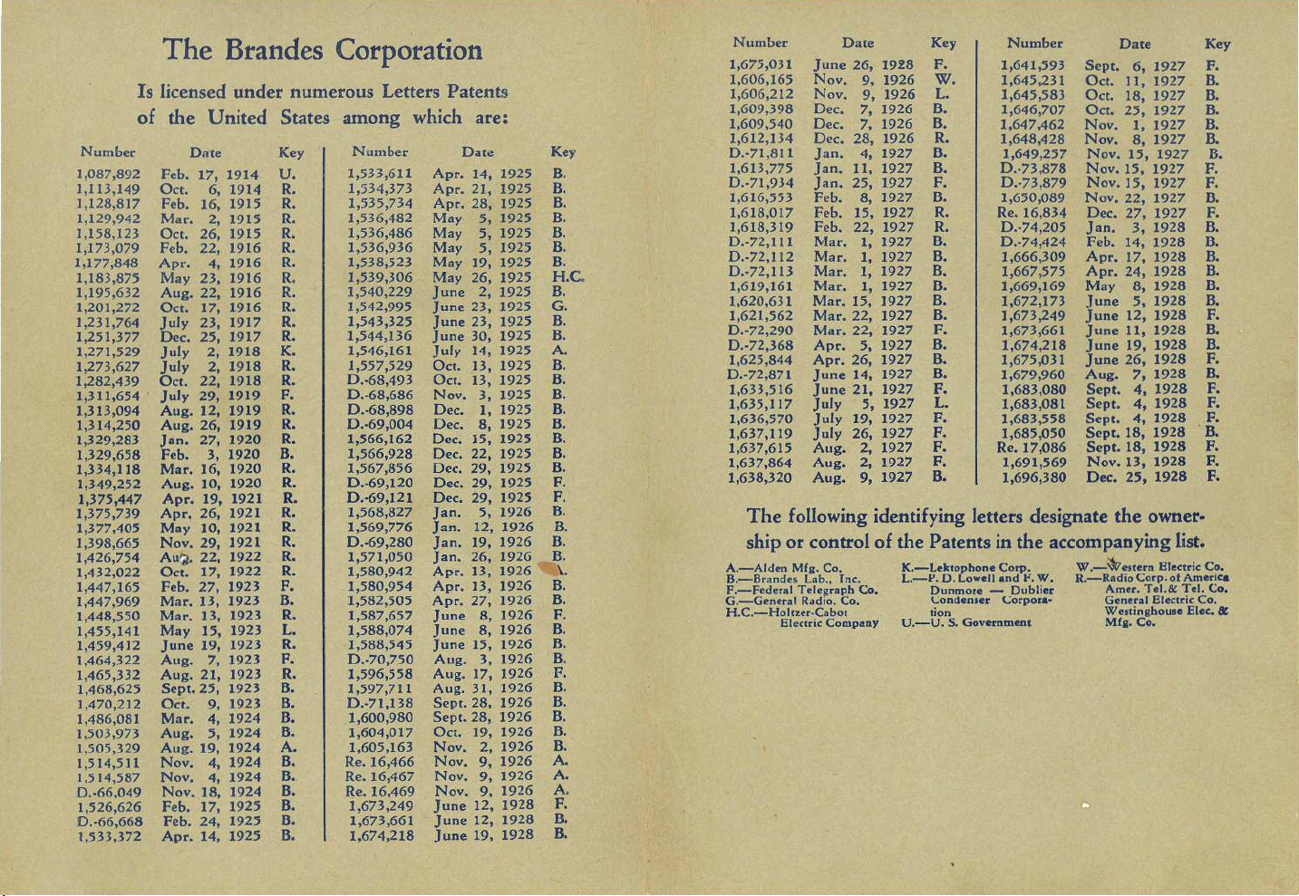
The Brandes Corporation
Number Date Key Number Date Key
1,675,031 June 26,1928 F. 1,641,593 Sept. 6, 1927 F.
Is licensed under numerous Letters Patents
1,606,165 Nov. 9, 1926
W.
1,645,231 Oct. 11, 1927 B.
1,606,212 Nov. 9, 1926
L.
1,645,583 Oct. 18, 1927 B.
of the United States among which are:
1,609,398 Dec. 7, 1926 B. 1,646,707 Oct. 25, 1927 B.
•
1,609,540 Dec. 7, 1926 B. 1,647,462 Nov.1, 1927 B.
Number Date Key Number Date
1,612,134 Dec.28, 1926 R. 1,648,428 Nov. 8, 1927 B.
Key0.-71,811 Jan.4,1927 B. 1,649,257 Nov.15,1927 B.
1,087,892 Feb.17,1914
U.
1,533,611 Apr. 14, 1925 B.1,613,775 Jan.11,1927 B. 0"73,878 Nov. 15, 1927 F.
1,113,149Oct. 6, 1914 R.1,534,373 Apr.21, 1925 B. 0.·71,934 Jan. 25, 1927 F. 0.-73,879 Nov. 15, 1927 F.
1,128,817 Feb. 16,1915 R.1,535,734 Apr. 28, 1925 B. 1,616,553 Feb. 8, 1927 B. 1,650,089 Nov. 22,1927 B.
1,129,942 Mar.2,1915 R. 1,536,482 May 5, 1925 B. 1,618,017 Feb. 15, 1927 R. Re.16,834 Dec.27, 1927F.
1,158,123 Oct. 26,1915 R. 1,536,486 May 5, 1925 B. 1,618,319 Feb.22, 1927 R. 0.-74,205 Jan.3, 1928 B.
1,173,079Feb. 22, 1916 R. 1,536,936 May 5, 1925 B. 0.-72,111 Mar. 1, 1927 B.0.-74,424 Feb. 14, 1928 B.
1,177,848 Apr. 4,1916 R. 1,538,523 May 19, 1925 B. 0.-72,112 Mar. 1, 1927 B. 1,666,309 Apr.17, 1928 B.
1,183,875 May 23, 1916 R.1,539,306 May 26, 1925
H.C.
0.·72,113 Mar. 1, 1927 B. 1,667,575 Apr. 24, 1928 B.
1,195,632 Aug. 22, 1916 R. 1,540,229 June 2, 1925 B. 1,619,161 Mar. 1, 1927 B. 1,669,169 May 8, 1928 B.
1,201,272 Oct. 17, 1916 R.1,542,995 June 23, 1925
G.
1,620,631 Mar.15, ]927 B. 1,672,173 June 5, 1928 B.
1,231,764 July 23,1917 R. 1,543,325 June 23, 1925 B.1,621,562 Mar. 22, 1927 B. ],673,249 June 12, 1928 F.
1,251,377 Dec. 25, 1917 R. 1,544,136 June 30, 1925 B. 0.·72,290 Mar.22, 1927 F. 1,673,661 June 11, 1928 B.
1,271,529 July 2, 1918 K. 1,546,161 July 14, 1925 A.0.·72,368 Apr.5, 1927 B. 1,674,218 June 19, 1928 B.
1,273,627 July 2, 1918 R. 1,557,529 Oct. 13, 1925 B. 1,625,844 Apr. 26, 1927 B. 1,675,031 June 26, 1928 F.
1,282,439 Oct. 22, 1918 R. 0.·68,493 Oct. 13, 1925 B. 0.·72,871 June 14, 1927 B. 1,679,960 Aug. 7, 1928 B.
1,311,654 July 29, 1919 F. 0.-68,686 Nov. 3, 1925 B. 1,633,516 June 21, 1927 F. 1,683,080 Sept.4, 1928 F.
1,313,094 Aug. 12, 1919 R. 0.-68,898 Dec. 1, 1925 B. 1,635,117 July 5, 1927
L.
1,683,081 Sept. 4, 1928
F.
1,314,250 Aug. 26, 1919 R. 0.·69,004 Dec. 8, ]925 B. 1,636,570 July 19, 1927 F. 1,683,558 Sept. 4, 1928 F.
1,329,283 Jan. 27, 1920 R. 1,566,162 Dec. 15, 1925 B. 1,637,119 July 26, 1927 F. 1,685,050 Sept. 18, 1928 .B.
1,329,658 Feb. 3, 1920 B. 1,566,928 Dec. 22, ] 925 B. 1,637,615 Aug. 2, 1927 F. Re.17,086 Sept. 18, 1928 F.
1,334,] 18 Mar. ]6, 1920 R. 1,567,856 Dec. 29, 1925 B. 1,637,864 Aug. 2, 1927 F. 1,691,569 Nov. 13, 1928 F.
1,349,252 Aug. 10, 1920 R. 0.·69,120 Dec. 29, 1925 F. 1,638,320 Aug. 9, 1927 B. 1,696,380 Dec. 25, 1928
F.
1,375,447 Apr. 19, 1921 R. 0"69,121 Dec. 29, 1925 F.
1,375,739 Apr. 26,1921 R. 1,568,827 Jan. 5, ]926 B.
The following identifying letters designate the owner·
1,377,405 May 10, 1921 R. 1,569,776 Jan. 12, 1926 B.
1,398,665 Nov.29, 1921 R. 0.-69,280 Jan. ]9, 1926 B.
ship or control of the Patents in the accompanying list.
],426,754 AulS. 22, 1922 R. 1,571,050 Jan. 26, ]926 B.
1,432,022 Oct. 17, 1922 R. 1,580,942 Apr. 13, 1926
\.
A.-Alden
Mfll.
Co. K.-Leklophone Corp. W.-~e"ern Electric Co.
1,447,165 Feb. 27,1923 F. 1,580,954 Apr. 13, 1926 B.
B.-Brandes Lab., Inc:.
L.-l'. D. Lowell and !'.W. R.-Radio Corp.of America
1,447,969 Mar. 13, 1923 B. 1,582,505 Apr. 27, 1926 B.
F.-Federal Telegraph Co. Dunmore - DubHe. Amer.Tel.& Tel.Co.
G.-General Radio.Co.
(;ondeoler <":orpor.·
General Electric Co.
1,448,550 Mar. 13, 1923 R. 1,587,657 June 8, 1926 F. H.C.-HollZer·Cabot
tion
We ••ingbouae Elec.
It
1,455,141 May 15, 1923
L.
1,588,074 June 8, 1926 B. Electric Company U.-U. S. Government
Mfa.
Co.
1,459,4]2 June 19, 1923 R. 1,588,545 June 15, 1926
8.
1,464,322 Aug. 7, 1923 F. 0.·70,750 Aug.3, 1926
8.
1,465,332 Aug. 21, ]923 R. 1,596,558 Aug. 17, 1926 F.
1,468,625 Sept. 25, 1923 B. 1,597,711 Aug. 31, 1926
8.
1,470,212 Oct. 9, 1923 B. 0.·71,138 Sept.28, 1926
8.
1,486,081 Mar.4, 1924 B. 1,600,980 Sept.28, 1926 B.
1,503,973 Aug. 5, 1924 B. 1,604,017 Oct. 19, 1926
8.
1,505,329 Aug. 19,1924 A. 1,605,163 Nov. 2, 1926 B.
1,514,511 Nov. 4, 1924 B. Re.16,466 Nov.9, 1926 A.
1.514,587 Nov. 4,1924
8.
Re.16,467 Nov.9, 1926 A.
D.·66,049 Nov.18, 1924 B. Re.16,469 Nov. 9, 1926 A.
1,526,626 Feb.17, 1925 B. 1,673,249 June 12,1928 F.
0.-66,668 Feb.24, 1925 B. 1,673,661 June 12, 1928B.
1,533,372 Apr. 14, 1925 B.1,674,218 June 19, 1928 B.