Kongsberg Seatex AIS 100 User manual

Seatex AIS 100
Instruction Manual

Blank page

iii
Document revisions
Document ID Rev. Date Reason for revision
0 - 3 Draft versions
4 2003-03-03 Updated NMEA descriptions
Man_instr_ais100_r5 5 2003-03-31 Minor update after internal revision
Software versions
This Instruction Manual applies to software version 1.06 and newer.

iv
Blank page

v
Table of contents
1 GENERAL INFORMATION ..................................................................1
1.1 Introduction...............................................................................1
1.2 How to use this manual...............................................................1
1.3 References ................................................................................1
1.4 Abbreviations and acronyms ........................................................2
1.5 AIS – Automatic Identification System ..........................................3
1.6 System components ...................................................................6
1.7 Electrical specifications................................................................8
2 OPERATION......................................................................................9
2.1 Introduction...............................................................................9
2.2 Operational modes .....................................................................9
2.2.1 Autonomous and continuous mode.................................9
2.2.2 Assigned mode ............................................................9
2.2.3 Polled or controlled mode............................................ 10
2.3 Malfunction and fallback arrangements ....................................... 10
2.4 Mobile station initialisation......................................................... 10
2.5 Overview................................................................................. 11
3 DISPLAY PAGES..............................................................................13
3.1 Main menu descriptions............................................................. 13
3.1.1 Navigational status..................................................... 13
3.1.2 Long range history ..................................................... 13
3.1.3 Voyage data.............................................................. 14
3.1.4 Static data ................................................................ 15
3.1.5 Dynamic data ............................................................ 16
3.1.6 Channel management................................................. 17
3.1.7 VHF link.................................................................... 18
3.1.8 Downperiods ............................................................. 18
3.1.9 Network & ports......................................................... 19
3.1.10 Answer modes........................................................... 19
3.1.11 Diagnostics ............................................................... 20
3.1.12 Security.................................................................... 21
3.2 Authorisation code entry ........................................................... 21
3.3 View page ............................................................................... 22
3.4 SMS menu............................................................................... 22
3.5 Alarms .................................................................................... 26
3.6 Adjusting brightness and contrast............................................... 26
4 TECHNICAL SPECIFICATIONS.........................................................27
4.1 Health, environment and safety ................................................. 27
4.2 Restrictions in guarantee........................................................... 27

vi
4.3 Physical dimensions.................................................................. 27
5 INSTALLATION...............................................................................33
5.1 General................................................................................... 33
5.2 AIS 100 MKD ........................................................................... 34
5.3 AIS 100 mobile station.............................................................. 35
5.4 AIS 100 connection box ............................................................ 37
5.5 External cabling of data signals.................................................. 41
5.6 AIS 100 VHF antenna................................................................ 42
5.7 AIS 100 GPS antenna ............................................................... 44
5.8 Internal alarm system............................................................... 46
6 EXTERNAL INTERFACES..................................................................47
6.1 External interfaces.................................................................... 47
6.2 Presentation interface ............................................................... 47
6.3 Long range interface................................................................. 49
6.4 Sensor input............................................................................ 49
6.5 New IEC 61162-1 sentences ...................................................... 51
6.6 IEC 61162-1, Ed. 2, sentences................................................... 70
6.7 Proprietary 61162-1 sentences................................................... 81
7 SOFTWARE SETUP PROCEDURE ......................................................85
7.1 Description of installation setup.................................................. 85
8 MAINTENANCE ...............................................................................89
8.1 General................................................................................... 89
8.2 Periodic maintenance................................................................ 89
8.3 Repairs and modifications.......................................................... 89
8.3.1 Exchange of antenna cable.......................................... 90
8.3.2 Exchange of GPS or VHF antennas ............................... 90
8.3.3 Repair of the Seatex AIS 100....................................... 90
8.4 Installation of a spare Seatex AIS 100 ........................................ 91
9 TROUBLESHOOTING .......................................................................93
9.1 Hardware problems .................................................................. 93
9.1.1 Power supply failing.................................................... 93
9.1.2 GPS and VHF antenna cable connections....................... 93
9.1.3 GPS and VHF antenna malfunction ............................... 93
9.1.4 GPS receiver failing .................................................... 94
9.1.5 VHF transceiver failing................................................ 94
9.2 External data interface problems................................................ 94
9.2.1 Data input from main GPS/GNSS source ....................... 94
9.2.2 Heading from vessel heading sensor............................. 95
10 PARTS LIST ....................................................................................97
APPENDIX A – VESSEL TYPES................................................................99
APPENDIX B – DECLARATION OF CONFORMITY...................................101
INDEX .................................................................................................103

vii
List of illustrations
Figure 1 Elements in an AIS system............................................................4
Figure 2 AIS 100 system components .........................................................6
Figure 3 Front display MKD unit................................................................11
Figure 4 MKD unit dimensions ..................................................................27
Figure 5 Mobile station dimensions ...........................................................28
Figure 6 Connection box dimensions .........................................................29
Figure 7 VHF antenna..............................................................................30
Figure 8 GPS antenna and pole dimensions................................................ 31
Figure 9 Rear side of the MKD unit and interconnection plug........................34
Figure 10 The Amphenol connector........................................................... 35
Figure 11 Recommended free space to rear side of mobile station ................ 36
Figure 12 Rear side of mobile station ........................................................36
Figure 13 The 9-pin D-sub plug................................................................ 37
Figure 14 Recommended free space to rear side of connection box...............38
Figure 15 The 50-pin plug........................................................................40
Figure 16 Talker and listener cabling – data/shield......................................41
Figure 17 Third wire cabling.....................................................................41
Figure 18 Recommended VHF antenna installation......................................42
Figure 19 VHF and GPS antenna cable connector termination.......................43
Figure 20 Recommended GPS antenna installation......................................44
Figure 21 GPS antenna offset arms........................................................... 45
Figure 22 Interfaces to the Seatex AIS 100 mobile station........................... 47

viii
Blank page

Seatex AIS 100 Instruction Manual, rev. 5 General information
1
1GENERAL INFORMATION
1.1 Introduction
Congratulations on the purchase of your new Seatex AIS 100 and
thank you for selecting what is one of the best AIS systems available
on the market today.
Kongsberg Seatex AS manufactures several positioning and
navigation products for all types of vessels, from fishery and merchant
marine vessels to advanced offshore and research vessels. Kongsberg
Seatex AS is located in Trondheim in the central part of Norway. The
company's involvements in positioning and navigation products began
in 1984 with equipment for offshore and research vessels. Professional
mariners around the world acknowledge the Seatex brand names as
the "leading edge" in advanced, accurate and reliable navigation and
positioning products.
1.2 How to use this manual
This manual is intended as a reference guide for operation, installation
and maintenance of the Seatex AIS 100 system. Great care has been
taken to simplify the setup and operation of the system.
Please take the time to read this manual to get a thorough
understanding of the Seatex AIS 100's components and operation, as
well as their relationship to other sensors interfaced to the system.
Before going into details about the Seatex AIS 100 a short
introduction to AIS – Automatic Identification system is presented.
The mobile station will also be referred to as a transponder.
1.3 References
[1] IEC 61993-2. MARITIME NAVIGATION AND
RADIOCOMMUNICATION EQUIPMENT AND SYSTEMS -
Automatic Identification Systems (AIS) Part 2: Class A Shipborne
equipment of the Universal Automatic Identification System (AIS) -
Operational and performance requirements, methods of test and
required test results. Committee draft for vote 2001-02-16.
[2] RECOMMENDATION ITU-R M.1371. TECHNICAL
CHARACTERISTICS FOR A UNIVERSAL SHIPBORNE
AUTOMATIC IDENTIFICATION SYSTEM USING TIME DIVISION
MULTIPLE ACCESS IN THE VHF MARITIME MOBILE BAND.
Draft Revision.

Seatex AIS 100 Instruction Manual, rev. 5 General information
2
[3] IEC 60945 Maritime navigation and radio communication equipment
and systems -General requirements - Methods of testing and required
test results. Third edition.
[4] IEC 60950 Safety of information technology equipment. Edition 3.0,
1999-04.
[5] IEC 61162-1 Ed. 2.0 (2000-07) Maritime navigation and radio
communication equipment and systems - Digital interfaces - Part 1:
Single talker and multiple listeners.
[6] IEC 61162-2 Ed. 1.0 (1998-09) Maritime navigation and radio
communication equipment and systems - Digital interfaces - Part 2:
Single talker and multiple listeners, high-speed transmission.
1.4 Abbreviations and acronyms
ABK Addressed and Binary Broadcast Acknowledgement
ABM Addressed Binary and Safety Related Message
ACA AIS Regional Channel Assignment
AIS Automatic Identification System
ALR Alarm
BIIT Built In Integrity Tests
BS Base Station
COG Course Over Ground
DGPS Differential GPS
DSC Digital Selective Calling
ECDIS Electronic Chart Display and Information System
ECS Electronic Chart System
EMC Electromagnetic Compatibility
ETA Estimated Time of Arrival
FATDMA Fixed Allocation TDMA
GNSS Global Navigation Satellite System
GPS Global Positioning System
HDG Heading
IALA International Association of Lighthouse Authorities
IEC International Electrotechnical Commission
IMO International Maritime Organisation
LAN Local Area Network
LED Light Emitting Diode
LR Long Range
MKD Minimum Keyboard Display
MMSI Maritime Mobile Service Identity
MSG Message
N/A Not Applicable
NMEA National Marine Electronics Association
PI Presentation Interface
PPS Pulse-per-second
PWR Power
ROT Rate of Turn
RTCM Radio Technical Commission of Maritime Service

Seatex AIS 100 Instruction Manual, rev. 5 General information
3
RX Receive
Seatex Kongsberg Seatex AS
SOG Speed Over Ground
SOTDMA Self Organising TDMA
SWR Standing Wave Ratio
TBD To Be Defined
TDMA Time Division Multiple Access
TX Transmit
TXT Text Message
UTC Universal Co-ordinated Time
VDL VHF Data Link
VDM VHF Data Link Message
VDO VHF Data Link Own Vessel Message
VHF Very High Frequency
VTS Vessel Traffic Service
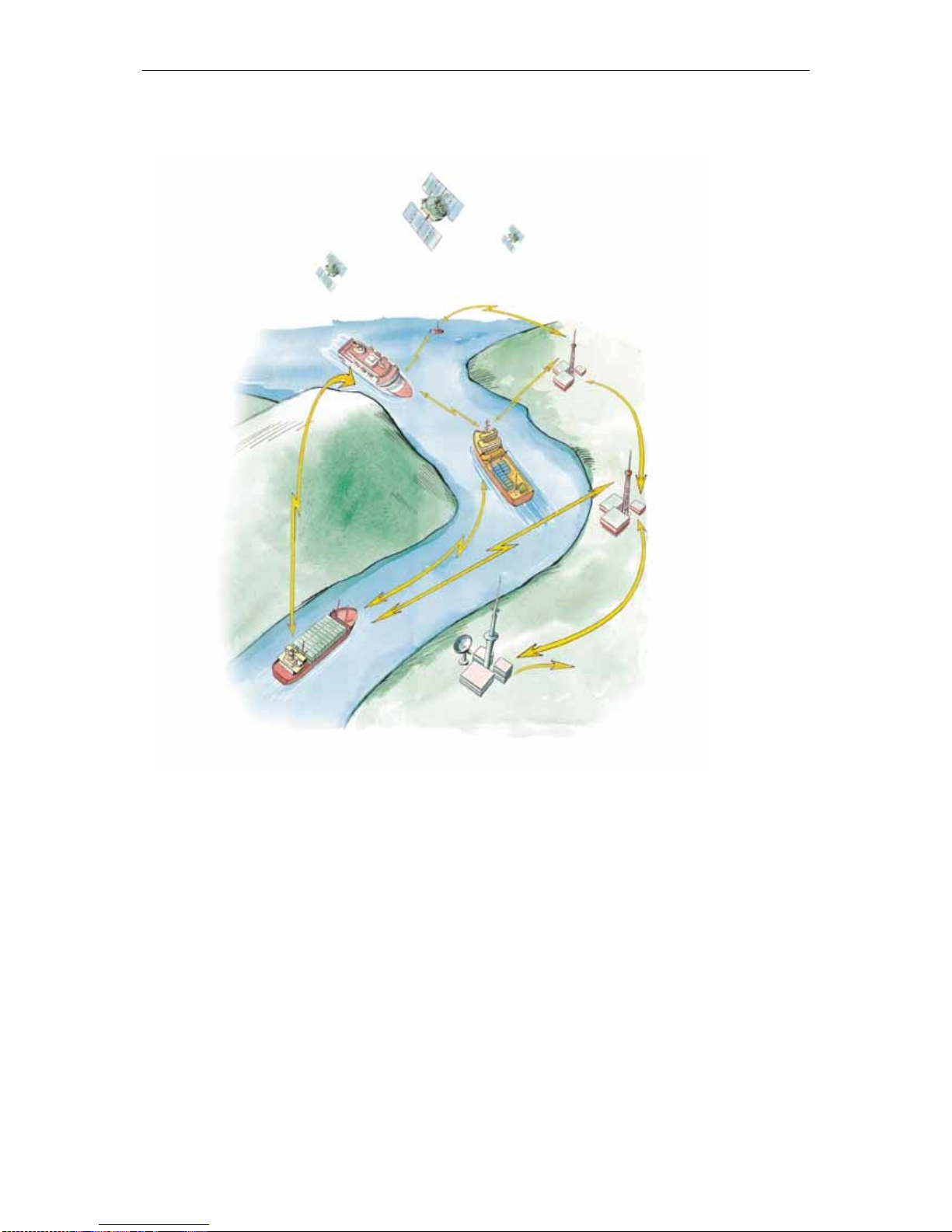
1.5 AIS – Automatic Identification System
AIS is an identification system that uses VHF communication to
transmit and receive AIS data. AIS operates primarily on two
dedicated VHF channels, AIS 1 – 161,975 MHz and AIS 2 – 162,025
MHz. Where these channels are not available regionally, the AIS can
be set to alternate designated channels.
The AIS mobile station broadcasts the vessel's position, speed and
course over ground as well as static and voyage related information.
Short safety related text messages can be sent between vessels or
broadcast from shore based AIS stations or Aids to Navigation like
buoys and lighthouses. The on-board installed mobile station is
designed to operate automatically and as a stand-alone unit. When not
transmitting, the mobile station listens for position information from
other vessels or shore based stations.
Seatex AIS 100 Instruction Manual, rev. 5 General information
4
Figure 1 Elements in an AIS system
The system broadcasts data using the SOTDMA (Self-organised Time
Division Multiple Access) data protocol. Each minute is divided into
4500 time slots, enabling simultaneous transmission of up to 500
stations.
Coverage
The system radio coverage range is similar to other VHF applications
and is dependent on the height of the antenna. The propagation differs
from that of a radar, due to the longer wavelength, so it is possible to
"see" around bends and behind islands if the landmasses are not too
high. A typical value to be expected at sea is 20 nautical miles.
AIS Base Station
VTS Centre
GNSS Satellites
AIS VHF Lin
k
AIS VHF Lin
k

Seatex AIS 100 Instruction Manual, rev. 5 General information
5
AIS information content
AIS type of information is exchanged automatically between vessels,
vessels and shore based stations and vessel and Aids to Navigation
like buoys and lighthouses. The information transmitted by the AIS
mobile stations is grouped in four categories:
Static Data
•MMSI (Maritime Mobile Service Identity) number
•Call sign and name
•IMO number
•Length and beam
•Type of ship
•Location of position fixing antennas on the ship
Voyage Related Data
•Ship's draught
•Hazardous cargo type
•Destination and ETA (at Master's discretion)
Dynamic Data
•Position with accuracy indication and integrity status
•Time in UTC
•COG (Course over ground)
•SOG (Speed over ground)
•Heading
•Navigational status
•Rate of turn
Safety-related Messages
•Reading and writing short safety related messages
Data reporting and transmission rates
AIS data as stated above is autonomously sent at different update rates
and thus reporting rates are dependent on the ship's navigational
mode. Dynamic information is dependent on speed and course
alteration while static and voyage related data are transmitted every 6
minutes or on request. Thus fast ferries will report their navigational
data at a higher update rate than ships at anchor.
Seatex AIS 100 Instruction Manual, rev. 5 General information
6
Type of Ship Reporting
Interval
Ship at anchor 3 min.
Ship 0 to 14 knots 12 sec.
Ship 0 to 14 knots and changing course 4 sec.
Ship 14 to 23 knots 6 sec.
Ship 14 to 23 knots and changing course 2 sec.
Ship > 23 knots 3 sec.
Ship > 23 knots and changing course 2 sec.
All data input to the AIS mobile stations is based on the NMEA 0183
data protocol. Messages sent on VHF are based on the AIS data
protocol, which defines several Message Types containing different
types of information.
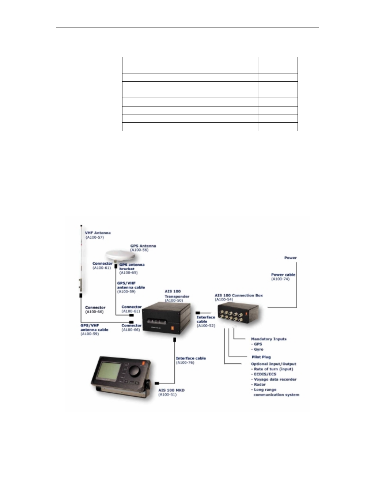
1.6 System components
The Seatex AIS 100 system consists of the following units:
Figure 2 AIS 100 system components

Seatex AIS 100 Instruction Manual, rev. 5 General information
7
AIS 100 Minimum Keyboard and Display (MKD)
The MKD unit provides a simple user interface to the mobile station.
The keypads on the MKD can be used to navigate between dedicated
menus used for configuration and display of vessel navigation data.
Text messages can also be entered into the MKD and transmitted to
other vessels or shore based AIS stations providing warnings or other
relevant navigation information. Thus the MKD provides basic
presentation of configuration data, position data and text messages. If
the AIS has been interfaced to the on-board ECDIS system or radar
the information displayed on the MKD can also be displayed on an
AIS compatible ECDIS or ECS systems.
AIS 100 mobile station
The mobile station incorporates two VHF receivers, configured to
operate on the predefined AIS frequencies for the region, one VHF
transmitter transmitting on all required frequencies and one DSC
receiver. The mobile station also incorporates a GPS receiver and a
processor. The internal GPS receiver, which is capable of receiving
differential corrections for increased position accuracy, is used for
time synchronisation and as a backup position sensor. For AIS data
transmission, the Self Organised Time Division Multiple Access
(SOTDMA) data protocol is used. SOTDMA enables a large number
of vessels to receive and transmit AIS data at the same time.
Front LED indicators
The LED indicators on the front of the mobile station can be used to
monitor status as well as data reception and transmission.
Led Colour Description
TX Off
Amber
Green
Red
Transmitter idle
Transmitting on AIS channel B
Transmitting on AIS channel A
Transmitter turned off
MSG Off
Amber
Green
No message/report being received
Message/report received on channel B
Message/report being received on channel A
GPS Amber
Green Indirect synchronisation free run
Internal GPS OK. GPS synch selected
ALM Off
Red No alarm
Alarm. Alarm relay activated
PWR Green Indicates powered unit

Seatex AIS 100 Instruction Manual, rev. 5 General information
8
AIS 100 connection box
The connection box is used to connect to external sensors main
position sensor, heading sensor and rate of turn sensor (when
available). These sensors are mandatory while interfaces to electronic
hart systems and long range communication systems, are optional.
AIS compatible ECDIS/ECS systems are interfaced to the AIS
through serial line communication. Power is supplied to the AIS
mobile station through the connection box.
AIS 100 VHF antenna
The VHF antenna is used for VHF communication. The antenna is
connected to the mobile station using cables with attenuation less than
3 dB.
AIS 100 GPS antenna
The GPS antenna is an L1 antenna receiving signals from all visible
satellites. The antenna is hermetically sealed and the cable used to
connect the GPS antenna to the mobile station should be of a quality
that ensures minimum loss of signal, i.e. less than 20 dB.
1.7 Electrical specifications
Input supply
Supply voltage 18 - 35 V DC
Supply current
@ 24 V DC 1.0 A (no VHF Tx)
1.2 A ( 2 W) VHF
1.6 A (12 W) VHF
Serial port capability
Mode RS-422
Isolation 1 kV
Line tolerant min +/- 15 V DC
Line speed 1200 - 57600 bits/s
Talker capability max 8 listeners @120 Ohm
Listener load requirements 120 Ohm (recommended)
Network
Network speed 10 Mbit/s

Seatex AIS 100 Instruction Manual, rev. 5 Operation
9
2OPERATION
2.1 Introduction
The AIS should always be in operation. It is recommended not to
switch off the AIS during port stays in order to provide information to
port authorities. In areas where piracy occurs, the master may switch
of the transmitter. If the transmitter is switched off, static data and
voyage related information will be stored.
2.2 Operational modes
After the unit has been installed and configured it operates
automatically without any user intervention. The mobile station has
three operational modes:
•Autonomous and Continuous mode
•Assigned mode
•Polled or Controlled mode
2.2.1 Autonomous and continuous mode
In the Autonomous and Continuous mode the mobile station
automatically defines its own reporting rate in accordance with its
navigational mode, speed and course. The unit also selects its own
data transmission slots. This is the normal mode for operation in all
areas but the mode may be switched to/from Assigned mode or Polled
or Controlled mode by a competent authority via a base station on
shore.
2.2.2 Assigned mode
A competent authority responsible for traffic monitoring may
remotely set transmission intervals and/or time slots for the vessel
mobile station. When operating in Assigned mode, the mobile station
will transmit position data on a slightly different format, AIS Message
Type 2, instead of the transmitted AIS Message Type 1. In Assigned
mode the mobile station does not change its reporting rate when
changing course and speed. Assignments are limited in time and will
be re-issued by the competent authority when needed. Thus, Assigned
mode only affects the transmission and not the reception of position
reports.

Seatex AIS 100 Instruction Manual, rev. 5 Operation
10
2.2.3 Polled or controlled mode
In this mode the mobile station will automatically respond to
interrogation messages from a ship or competent authority. The
response is transmitted on the channel where the interrogation
message was received. Operation in Polled or Controlled mode does
not conflict with operation in the other two modes.
2.3 Malfunction and fallback arrangements
The mobile station has built-in integrity testing to continuously verify
own operational status and notify user and external equipment if any
malfunction is detected. Part of this test monitors the transmitter and
receiver modules. Alarm status will be transmitted to the PI port in
addition to triggering the alarm relay.
Malfunction type Malfunction source
Tx malfunction
ID 001 Tx frequency is not locked or
Tx power is measured outside setting
SWR 3:1 malfunction
ID 002 SWR is measured to more than 3:1
ChA malfunction (RX1)
ID 003 ChA frequency is not locked
ChB malfunction (RX2)
ID 004 ChB frequency is not locked
Rx DSC malfunction
ID 005 Ch70 frequency is not locked
2.4 Mobile station initialisation
The mobile station will automatically switch on when power is
applied to the unit by connecting the power cable in the connection
box. There is no on/off switch and thus power is removed by
disconnecting the power cable in the connection box.
•After power has been applied, wait for the two-minute
initialisation period.
•At completed initialisation all LEDs will go amber.
•The mobile station is ready for operation when the GPS LED is
blinking at one-second intervals.
•The View page will appear on the MKD.
Seatex AIS 100 Instruction Manual, rev. 5 Operation
11
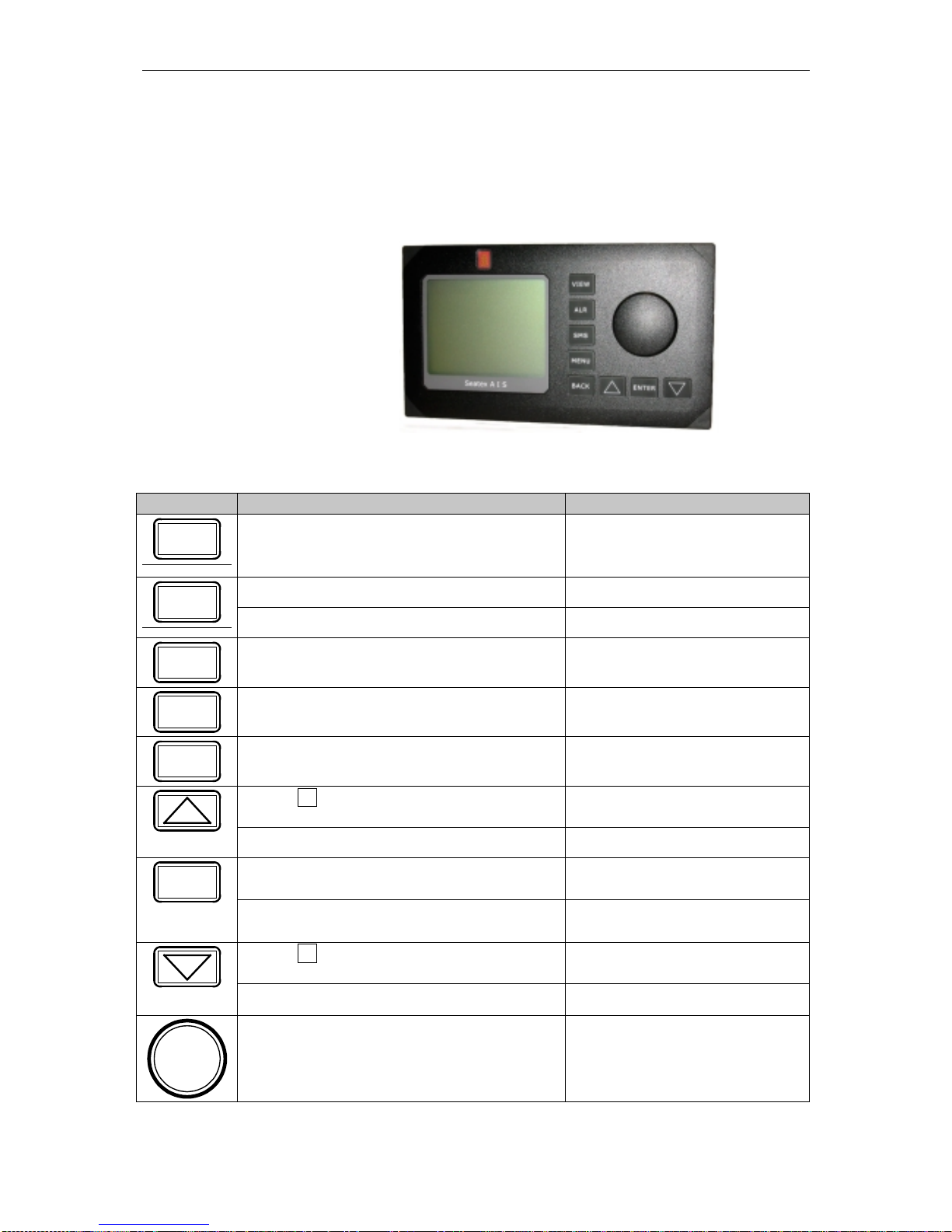
2.5 Overview
The default view of the display shows vessel own position along with
course (degrees) and speed (knots) over ground. Other vessels are
shown in ascending order relative to own vessel position.
Figure 3 Front display MKD unit
Buttons [Condition] Action Function
VIEW [Always] Pressed once Displays the View page
[Always] Pressed once Displays the Alarms page
ALR [Always] Pressed more than once Displays the Long Range page
SMS [Always] Pressed Displays the SMS Menu page
MENU [Always] Pressed Displays the Main Menu page
BACK [Always] Pressed Displays the previous page
[When present in lower right corner]
Pressed Displays previous subpage
[When writing/editing] Moves highlighting up
[When choice is highlighted] Pressed Selects highlighted choice
ENTER
[When nothing is highlighted] Pressed No action
[When present in lower right corner]
Pressed Displays next subpage
[When writing/editing] Pressed Moves highlighting down
[When choice is highlighted] Rotated either
way Moves highlighting

Seatex AIS 100 Instruction Manual, rev. 5 Operation
12
Blank page
Table of contents
Popular Car Navigation System manuals by other brands

Toyota
Toyota Toyota navigation system Quick reference guide

Blaupunkt
Blaupunkt TravelPilot 55 Active instruction manual

Porsche
Porsche PCM Installation and conversion instructions

ZENEC
ZENEC Z-E3726 Installation guidelines

Kia
Kia LAN1100EKTF Serivce manual

Raymarine
Raymarine G-Series system Quick reference guide


Mercedes-Benz
Mercedes-Benz COMAND operating instructions

CHURCHILL NAVIGATION
CHURCHILL NAVIGATION ION user manual

Magellan
Magellan RoadMate 1212 - Automotive GPS Receiver Manuel d'utilisation

Simrad
Simrad MX510 user manual

Snooper
Snooper 6 Series user manual

Magellan
Magellan RoadMate 6000T - Automotive GPS Receiver Manuale di riferimento