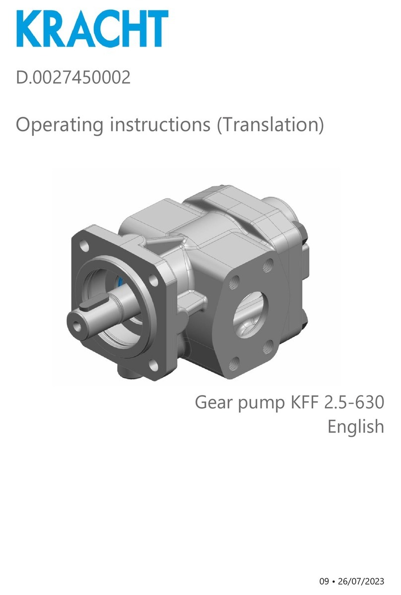
Kracht BT Series User manual

D.0026290002
Operating instructions (Translation)
Gear pump BT / BTH
88026290002-04
Englisch
2021-02-05

Table of Content
1 General 5
1.1 About the documentation 5
1.2 Manufacturer´s address 5
1.3 Applicable documents 5
1.4 Symbolism 6
2 Safety 7
2.1 Intended use 7
2.2 Personnel qualification and training 7
2.3 Basic safety instructions 7
2.4 Basic hazards 8
3 Device description 10
3.1 Functional principle 10
3.2 Basic design 12
3.2.1 Basic design BT 0 12
3.2.2 Basic design BT 1-7 13
3.2.3 Basic design BTH 1-3 14
3.2.4 Heating connections BTH 15
3.3 Rotation and delivery direction 16
3.4 Type key 17
3.4.1 Type key BT 17
3.4.2 Type key BTH 18
3.5 Important special numbers 19
4 Technical data 20
4.1 General information 20
4.2 Housing connection/Connection type 21
4.2.1 Housing connection BT 21
4.2.2 Housing connection/Connection type BTH 21
4.3 Viscosity - Rotation speed assignment 22
4.4 Operating pressure of suction side and pressure
side 22
4.5 Dimensions 22

4.6 Weights 23
4.6.1 Weight BT 23
4.6.2 Weight BTH 23
5 Transport and storage 24
5.1 General 24
5.2 Transport 24
5.3 Storage 25
6 Installation 27
6.1 Safety instructions for installation 27
6.2 Noise reduction 28
6.3 Mechanical installation 28
6.3.1 Preparation 28
6.3.2 Pumps with free shaft end 28
6.3.3 Coupling Type "R." 30
6.4 Connection lines 34
6.4.1 General 34
6.4.2 Suction line 35
6.4.3 Pressure line 36
6.4.4 Mounting Connection lines 36
6.5 Change of the direction of rotation 36
7 Operation start-up 40
7.1 Safety instructions for start-up 40
7.2 Preparation 40
7.3 Adjustment of the gland packing 40
7.4 Further operation start-up 41
8 Removal 43
8.1 Safety instructions for removal 43
8.2 Removal 44
9 Maintenance 45
9.1 Safety instructions for maintenance 45
9.2 Maintenance work 45
9.3 Maintenance instructions 46

1 General
1.1 About the documentation
These operating instructions describe the installation, operation and mainte-
nance of the following device:
Gear pump BT / BTH
The device is manufactured in different versions. Information about the ver-
sion concerned in the individual case can be found on the device's type plate.
These operating instructions are a component of the device and must be kept
accessible for the personnel near the device at all times.
If you have any questions about these operating instructions, please contact
the manufacturer.
1.2 Manufacturer´s address
KRACHT GmbH
Gewerbestraße 20
DE 58791 Werdohl
phone: +49 2392 935-0
fax: +49 2392 935-209
email: [email protected]
web: www.kracht.eu
1.3 Applicable documents
1. KTR Kupplungstechnik GmbH, DE 48407 Rheine
○KTR-N 40210: Coupling operating/assembly instruction Rotex
Excerpts from these documents are included in these operating instructions.
If required, the original documents can be requested from the respective
manufacturer.
Gear pump BT / BTH
88026290002-04 2021-02-05 5

1.4 Symbolism
DANGER
Identificationofanimmediatehazard,whichwouldresultindeathorsevere
bodily injury if not avoided.
WARNING
Identification of a potential medium risk hazard, which would lead to death
or severe bodily injury if not avoided.
CAUTION
Identification of a low risk hazard, which could lead to minor or medium
bodily injury if not avoided.
NOTICE
Flagging of notices to prevent property damage.
Identification of basic safety instructions. Non-compliance can lead to haz-
ards for people and the device.
Flagging of special user tips and other especially useful or important infor-
mation.
Gear pump BT / BTH
62021-02-05 88026290002-04

2 Safety
2.1 Intended use
1. The device has been designed for operation with fluid. Dry operation is
not permitted.
2. The device may be operated in filled condition only.
The medium must be compatible with the materials used in the device.
The chemical competence is necessary for this. Be careful with ethylene
oxide or other cathalytic or exothermic or self-decomposing materials.
Please consult the manufacturer in cases of doubt.
3. Thedevicemaybeoperatedonlyinusualindustrialatmospheres.Ifthere
are any aggressive substances in the air, always ask the manufacturer.
4. Operation of the device is only permissible when complying with the op-
erating instructions and applicable documents.
Deviating operating conditions require the express approval of the man-
ufacturer.
5. In case of any use of the device not according to specification, any war-
ranty is voided.
2.2 Personnel qualification and training
The staff designated to assemble, operate and service the device must be
properly qualified. This can be through training or specific instruction. Per-
sonnel must be familiar with the contents of this operating instructions.
Read the operating instructions thoroughly before use.
2.3 Basic safety instructions
1. Comply with existing regulations on accident prevention and safety at
work along with any possible internal operator regulations.
2. Pay attention to the greatest possible cleanliness.
3. Wear suitable personal protection equipment.
4. Do not remove, make illegible or obliterate type plates or other referen-
ces on the device.
5. Do not make any technical changes on the device.
6. Maintain and clean the device regularly.
7. Use spare parts approved by the manufacturer only.
Gear pump BT / BTH
88026290002-04 2021-02-05 7

2.4 Basic hazards
DANGER
Hazardous fluids!
Danger of death when handling hazardous fluids.
1. Comply with the safety data sheets and regulations on handling haz-
ardous fluids.
2. Collect and dispose of hazardous fluids so that no hazards arise for
people or the environment.
DANGER
Rotating parts!
Danger of death due to body parts, hair or clothing getting trapped or en-
tangled.
1. Before all work, ensure that existing drives are voltage-free and pres-
sure-free.
2. Securely prevent restarting during all work.
DANGER
Rotating parts!
Danger of death due to body parts, hair or clothing getting trapped or en-
tangled.
1. Take measures against accidental touching of rotating parts.
WARNING
Rotating parts!
Danger of injury from flying parts.
1. Enclose rotating parts so as to avoid any danger from flying parts in the
event of breakage or malfunction.
WARNING
Failure of load-carrying parts due to overload!
Danger of injury from flying parts.
Danger of injury from spurting fluids.
1. Depressurisethedevice and allconnectionlines before doing anywork.
2. Securely prevent the restoration of pressure while working on the de-
vice.
Gear pump BT / BTH
82021-02-05 88026290002-04

WARNING
Failure of load-carrying parts due to overload!
Danger of injury from flying parts.
Danger of injury from spurting fluids.
1. Use only connections and lines approved for the expected pressure
range.
2. Securely prevent exceeding the permissible pressure, e.g. by using
pressure relief valves or rupture discs.
3. Design pipework so that no tensions, e.g. caused by changes in length
due to fluctuations in temperature, are transmitted to the device.
WARNING
Failure of load-carrying parts due to overload!
Danger of injury from flying parts.
Danger of injury from spurting fluids.
1. Do not operate the device against closed shut-off devices.
2. Do not operate the device in the false direction of rotation.
Gear pump BT / BTH
88026290002-04 2021-02-05 9

3 Device description
3.1 Functional principle
BT / BTH series pumps are external gear pumps that work according to the
positive displacement principle.
S = Suction connection
P = Pressure connection
When rotated, two gearwheels meshing together produce a volume enlarge-
ment as a result of the opening of the tooth spaces on the suction side (S),
so that medium can flow in and so that a corresponding volume is displaced
simultaneously by immersion of the teeth into the filled tooth spaces on the
pressureside (P). Fluidtransporttakes placethroughentrainment inthetooth
gaps along the wall of the wheel chamber. The so-called geometric flow rate
Vgis being displaced per wheel rotation.
The actually delivered amount of liquid does not correspond with the theo-
retical value, it is being reduced through losses due to the necessary toler-
ances. The losses are less the lower the operating pressure and the higher
the viscosity of the medium.
Gear pumps are self-priming within wide limits. The displacement cycle de-
scribe initially takes place without exhibiting appreciable pressure build-up.
Only after setting external loads, for example, through delivery heights, flow
resistances, line elements, etc. will the required working pressure arise to
overcome these resistances.
As usual with non-axial play compensated pumps, the lateral clearance be-
tween gear and front face has been set in such a way that the maximum
allowable operating pressure is managed in an adequate and secure way.
Bearingandshaft seal of the device are lubricated by the media. The device's
operating life will be reduced if the medium contains abrasive ingredients.
Gear pump BT / BTH
10 2021-02-05 88026290002-04

Gear pump BTH
BTH series pumps are ideal for conveying high-viscosity media that must be
heated to be capable of flow, e.g. bitumen or wax.
The housing has a double-wall design (jacket heater). The working chamber
of the pump is heated by the heating medium (such as heat-transfer oil, water
or steam), which will be fed and discharged via dedicated inlets and outlets.
1. Heating medium outlet (HA)
2. Heating chamber
3. Working chamber
4. Pumping medium inlet or outlet
5. Heating medium inlet (HE)
(optionally right, left, right and left)
Gear pump BT / BTH
88026290002-04 2021-02-05 11

3.2 Basic design
3.2.1 Basic design BT 0
Explanation
1. Cover 5. Packing ring
2. Liquid gasket 6. Gland compression ring
3. Driven shaft 7. Cap nut
4. Housing 8. Driving shaft
Gear pump BT / BTH
12 2021-02-05 88026290002-04

3.2.2 Basic design BT 1-7
Explanation
1. Front cap 6. Driving shaft
2. Plain bearing bush 7. Gland cap
3. Liquid gasket 8. Packing ring
4. Driven shaft 9. Gland follower
5. Housing
Gear pump BT / BTH
88026290002-04 2021-02-05 13

3.2.3 Basic design BTH 1-3
Explanation
1. End cover 7. Gland cap
2. End cover 8. Packing ring
3. Driving shaft 9. Gland follower
4. Housing 10. Gasket
5. Driven shaft 11. Gasket
6. Plain bearing bush
Gear pump BT / BTH
14 2021-02-05 88026290002-04

3.2.4 Heating connections BTH
HE= Heating connection Inlet
HA= Heating connection Outlet
Gear pump BT / BTH
88026290002-04 2021-02-05 15

3.3 Rotation and delivery direction
The following definition applies with respect to the rotation and delivery direction of
external gear pumps for pump connections positioned below the drive shaft:
Lookingatthe pump shaft end, the pump-
ing flow is from left to right when the shaft
is moving clockwise.
Looking at the pump shaft end, the pump-
ing flow is from right to left when the shaft
is moving counterclockwise.
BTH
S = Suction side
P = Pressure side
BT
BT series pumps work independently of the rotational direction.
Gear pump BT / BTH
16 2021-02-05 88026290002-04

3.4 Type key
3.4.1 Type key BT
Available design variants BT
BT 0 B Z 0 A C 51 /...
BT 2 B Z 0 R T 51
54 /...
BT 1-4 B Z 0 U S
T51
54 /...
BT 1-7 B Z 0 B
CK51
54 /...
1. 2. 3. 4. 5. 6. 7. 8. 9.
Explanation of type key BT
1. Serie
2. Size
0Vg= 6,9 cm³/r 4Vg= 197 cm³/r
1Vg= 32 cm³/r 5Vg= 254 cm³/r
2Vg= 43 cm³/r 6Vg= 352 cm³/r
3Vg= 91 cm³/r 7Vg= 494 cm³/r
3. Direction of rotation
BClockwise and counterclockwise, Flow direction alternating
4. Housing connection
ZWhitworth pipe thread
5. Design serial number (specified by manufacturer)
6. Housing design and bearing support
AHousing: EN-GJL-200 (GG 20) UHousing: CuSn12 (Bronze)
Bearing: EN-GJL-200 (GG 20) Bearing: CuSn12 (Bronze)
BHousing: EN-GJL-200 (GG 20) RHousing: 1.4308 (Stainless steel)
Bearing: CuSn7ZnPb (Bronze) Bearing: CY10C (Carbon)
CHousing: EN-GJL-200 (GG 20)
Bearing: SINT B-00 (Sintered iron)
7. Gears version
C1.7139 (Case-hardened steel) Unhardened SShaft/Bolt: 1.4057 (Stainless steel)
Gear: CuSn12 (Bronze)
K1.7139 (Case-hardened steel) Hardened T1.4308 (Stainless steel) Tempered
Gear pump BT / BTH
88026290002-04 2021-02-05 17

Explanation of type key BT
8. Seal type
51 Gland packing Arolan II 54 Gland packing HT 98
Liquid gasket Loctite 540 (Housing) Liquid gasket Loctite 540 (Housing)
9. Special number for special versions
See section 3.5 “Important special numbers”
3.4.2 Type key BTH
Available design variants BTH
BTH
1/. R
L
Z
F
G0B
CK51 /...2/.
3/. F
1. 2. 3. 4. 5. 6. 7. 8. 9.
Explanation of type key BTH
1. Serie
2. Size
1/55 Vg= 97 cm³/r 2/130 Vg= 510 cm³/r
1/105 Vg= 186 cm³/r 3/150 Vg= 1056 cm³/r
2/100 Vg= 393 cm³/r
3. Direction of rotation
RClockwise LCounterclockwise
4. Housing connection/Connection type
ZWhitworth pipe thread GFlange connection with counter
flange
FFlange connection
5. Design serial number (specified by manufacturer)
6. Housing design and bearing support
BHousing: EN-GJL-200 (GG 20) CHousing: EN-GJL-200 (GG 20)
Bearing: CuSn7ZnPb (Bronze) Bearing: SINT B-00 (Sintered iron)
7. Gears version
K1.7139 (Case-hardened steel) Hard-
ened F1.7139 (Case-hardened steel) Hard-
ened
8. Seal type
51 Gland packing Arolan II
Gasket C4400 (Housing)
9. Special number for special versions
Gear pump BT / BTH
18 2021-02-05 88026290002-04

3.5 Important special numbers
Special
number Serie/Size Description
04 BT 1 - 7 Ni/SiC dispersion anti-wear/corrosion layer on:
Housing; Gears; Bearing bush
12 BT 1 - 7 Drive shaft, bottom mounted
17 BT 1 - 7 Ni/SiC dispersion anti-wear/corrosion layer on:
Gears; Bearing bush
21 BT 0 - 7 Diameter of trunnion and outer diameter of gear wheel cut to sub-stand-
ard size
25 BT 3 Drive shaft, bottom mounted
Housing connection:
Whitworth pipe thread G 1 1/4"
29 BT 1 - 7 Ni/SiC dispersion anti-wear/corrosion layer on:
Bearing bush
Gear pump BT / BTH
88026290002-04 2021-02-05 19

4 Technical data
4.1 General information
General information BT / BTH
Design External gear pump
Fixing type Foot mounting
End of drive shaft Cylindrical
Housing connection/Connec-
tion type See section 4.2 “Housing connection/Connection type”
Mounting position Horizontal
Viscosity νmin 76 mm2/s
νmax 30000 mm2/s
Ambient temper-
ature ϑu-10 °C ≤Ta≤60 °C
Speed (1) nmin. 100 rpm
nmax. 750 rpm
Operating pres-
sure pe
pb
See section 4.4 “Operating pressure of suction side and pres-
sure side”
Max. pressure in-
side jacket heater ph max. 10 bar
Max. temperature
of heating medi-
um
ϑh max. 160 °C
Fluid tempera-
ture
ϑm min. -10 °C
ϑm max 220 °C
External loads on shaft end Axial and radial forces are not allowed.
Material See section 3.4 “Type key”
Permissible me-
dia
BT Lubricating fluids without abrasive components.
(Petrols, solvents, etc. are not permissible.)
BTH
BT .../04 Fluids with abrasive constituents and/or highly corrosive activity
such as resins, some colours, lacquers, and glues.
(1) See also section 4.3 “Viscosity - Rotation speed assignment”
Gear pump BT / BTH
20 2021-02-05 88026290002-04
This manual suits for next models
12
Table of contents
Other Kracht Water Pump manuals