Kramer GP2-890RR 2024 User manual

OWNER’S MANUAL
GP2-890RR
(Model Year 2024)

2Introduction
About This Manual
Use this manual as a guide for proper procedures for this motorcycle’s
basic operation, inspection, and maintenance. This manual is intended
for professional service technicians and those knowledgeable about
appropriate safety training and safe shop practices.
If you have any questions concerning the operation or maintenance of
your motorcycle, please consult your Krämer dealer.
All information, directions, photographs, and specications included
in this manual are based on the most current information at the time
of publication. Krämer Motorcycles accepts no liability for delivery
options, deviations from illustrations and descriptions, misprints, or
other errors. Krämer Motorcycles reserves the right to make changes
at any time without notice or obligation.
This motorcycle is to be raced on a closed course only. Krämer
Motorcycles & Krämer Motorcycles USA are not liable for any injury to
riders, mechanics, public, and any damage to the vehicle or property.
This manual is for the following models:
2024 Krämer GP2-890RR
Version: GP2-890RR-2023-11-28
Introduction
Dear Krämer Customer,
We want to congratulate you on purchasing a Krämer GP2-890RR series motorcycle.
The GP2-890RR is equipped with class-leading specications, including the best
power-to-weight ratio in the category, with 138 hp on-tap and a ready-to-race weight
of 142 kg (313 lbs). As the highest evolution of the critically regarded GP2 platform,
the RR-spec brings traction control and wheelie control to the offering, along with
improved aerodynamics and rened chassis characteristics.
Propelling the Krämer GP2-890RR to the front of the pack is an 889cc parallel-
twin motor from KTM, which produces 138hp (101 kW) at 10,100 rpm and 100 Nm
(74 lbs-ft) of torque at 8,200 rpm. An increased redline of 11,500 rpm comes to the
GP2-890RR as well, thanks to new lightweight engine internals and advanced engine
management software.
Making no compromises, the Krämer GP2-890RR is engineered to take you to the
peak of performance - entering new dimensions on the race track!
This manual will serve as a guide to keeping your GP2-890RR in race-ready shape.
THIS VEHICLE IS SOLD AS IS, NO WARRANTY.
Enter the serial numbers of your vehicle:
Vehicle identication number
____________________________________
Engine number
____________________________________
Dealer’s Stamp
Krämer Motorcycles
Gewerbepark Lindach B5
84489 Burghausen
Germany
www.kraemer-motorcycles.com
© 2023 Krämer Motorcycles
All rights reserved.

3
General Information
Table of Contents
USAGE AND SETUP
Identication / Serial Numbers ...........4
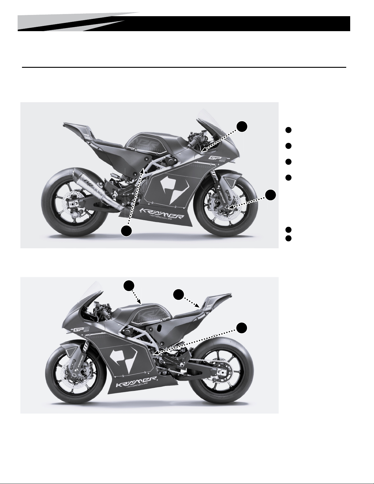
Reference Views of Vehicle..............4
Serial Numbers .....................4
Operating Components ...............4
Control Components ...................5
Start Up Procedure ....................5
Shut Down Procedure ..................5
Vehicle Break-in Procedure..............6
Pre-Ride Inspection....................6
Post-Race Service .....................6
Post-Crash Inspection ................6
Transporting / Loading .................7
Raising the Motorcycle on Lift Stands .....7
Storage .............................8
MAINTENANCE / SERVICE
Service Schedule......................9
Krämer Motorcycles Onlineshop ..........9
Checking the Engine Oil Level ...........9
Changing the Engine Oil & Filter,
and Cleaning the Oil Screens ..........9
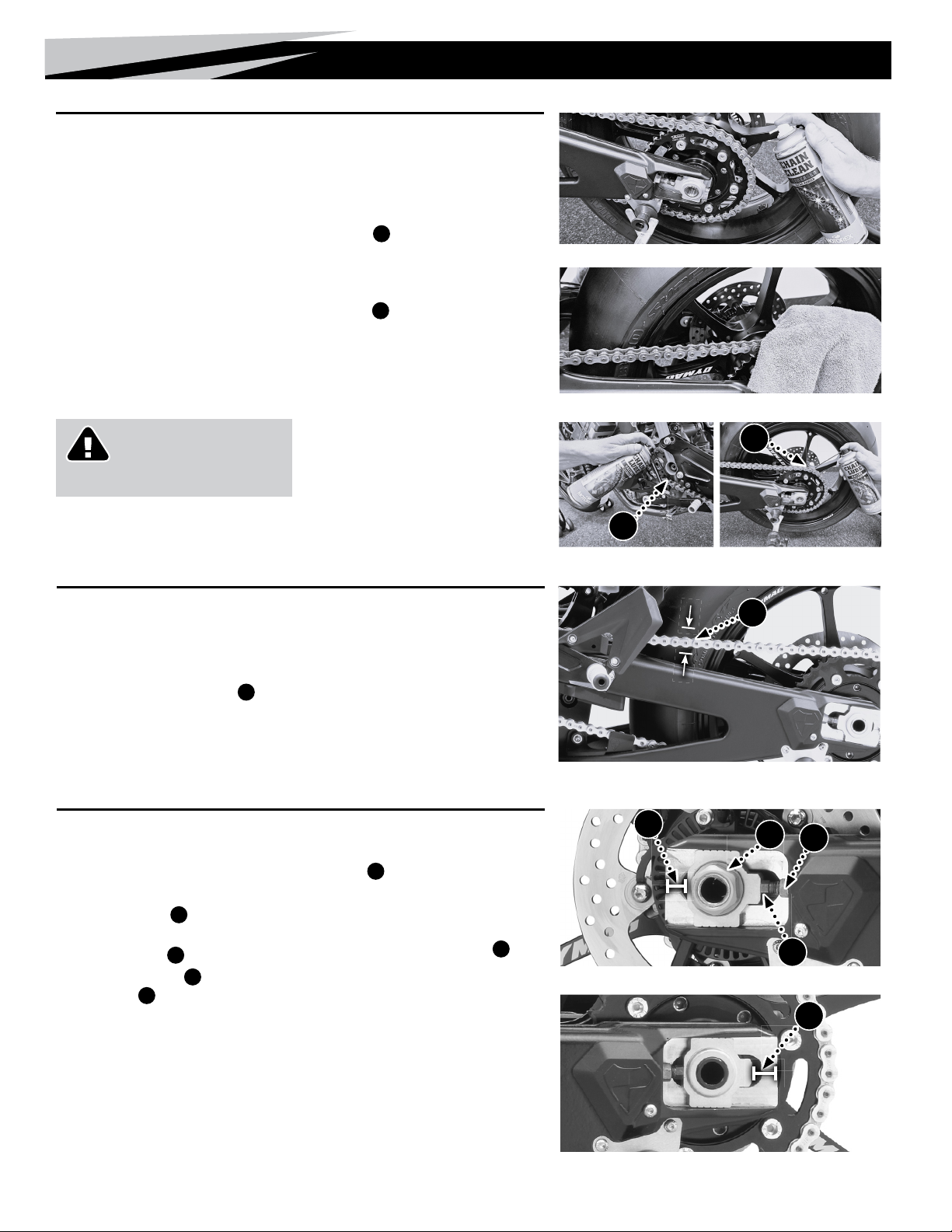
Chain Cleaning / Lubrication............10
Checking the Chain Tension ............10
Adjusting the Chain Tension / Rear Axle
Alignment ........................10
Fuel Filler Cap ....................... 11
Air Filter Servicing....................11
ENGINE
Repairs. . . . . . . . . . . . . . . . . . . . . . . . . . . . . 12
Recommended Engine Maintenance......12
Engine Modes .......................12
Traction Control ......................12
Wheelie Control ......................12
Pit Limiter ..........................12
COOLING SYSTEM
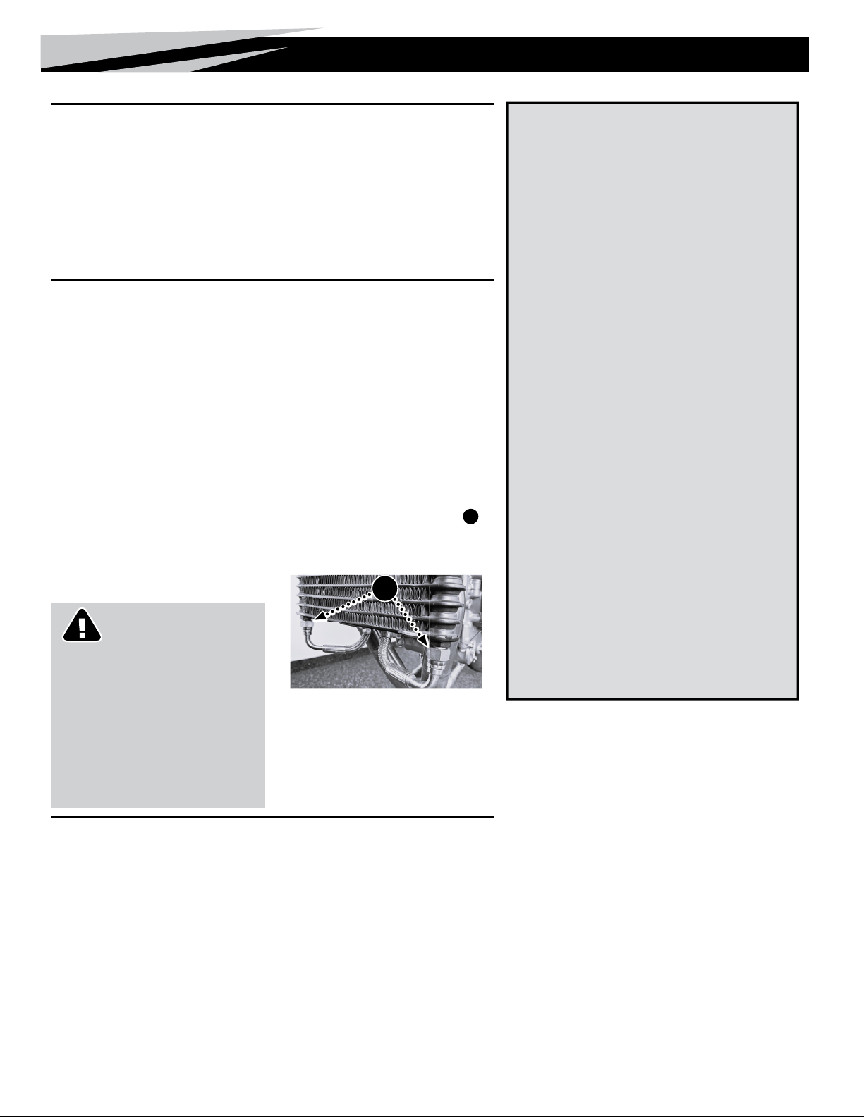
Checking the Coolant Level.............13
Draining the Coolant ..................13
Filling/Bleeding the Cooling System ......13
CHASSIS
Handlebar Adjustment.................14
Steering Damper Setup ................14
Seat/Tank Height Adjustment ...........14
Bodywork Removal ...................15
Bodywork Installation .................15
Fuel Tank Draining Procedure ...........16
Fuel Tank Removal/Installation..........16
Clutch Lever Free Play and Reach
Distance ......................... 17
Front Brake Lever Response and Travel
Distance ......................... 17
Rearset Setup .......................18
Adjusting the Foot Pegs................18
Rear Brake Lever Adjustment ...........18
Shift Lever Height Adjustment...........18
BRAKE SYSTEM
Brake Inspection .....................19
Brake Bleeding ......................19
Changing the Brake Pads ..............20
SUSPENSION
Suspension Inspection.................21
Checking the Steering Head Bearing Play..21
Adjusting the Steering Head Bearing Play..21
Changing the Fork Offset...............22
Fork Suspension Settings ..............23
Adjusting Spring Preload...............23
Adjusting Compression Damping.........23
Adjusting Rebound Damping ............23
Fork Specications ...................23
Rear Shock Suspension Settings.........24
Adjusting the Spring Preload ...........24
Adjusting Compression Damping.........24
Adjusting Rebound Damping ............24
Shock Absorber Specications ..........24
WHEELS
Front Wheel Removal .................25
Front Wheel Installation ...............25
Rear Wheel Removal ..................26
Rear Wheel Installation ................26
ELECTRICAL
Tail light Operation....................27
Charging the Tail light .................27
Fuses ..............................27
Battery.............................28
Wiring Diagram ......................28
TECHNICAL DATA
GP2 890-RR Specications.............30
Fluid Capacities ......................30
Engine Specications .................30
Electrical System.....................30
TORQUE SPECIFICATIONS
Engine Torque Chart ..................31
Chassis Torque Chart..................32
Safety Wire .........................32
DASHBOARD
AIM MXS 1.3 Race GPS with Data Logger . 33
Dash Logger Indicators Overview ........33
Dash Logger Menu Conguration Settings . 34
Set Date and Time..................34
Set Backlight......................34
Set Video Input ....................34
Lap Time Setup....................35
Counters Management ..............35
GPS & Tracks .....................35
Wi-Fi Management .................36
System Info .......................36
GPS Search.......................36
Sampled Data Recall................37

4Usage and Setup
Usage and Setup
Right Side View
Left Side View
A
C
E
F
D
Identification / Serial Numbers
Serial Numbers
AChassis S/N — R.H. side
steering head.
BEngine S/N — L.H. side of the
engine above the sprocket.
CFork S/N — inside the axle
clamp.
DShock S/N — top section of
shock.
Operating
Components
EFuel Fill
FIntake Cover/Air Filter Box
B
Reference Views of Vehicle NOTE: Instructions, such as right-hand (R.H.) side and left-hand (L.H.) side
are from rider position.

5
Usage and Setup
Control Components
Hand Controls
ADashboard
BMain Switch
(behind fairing support)
CClutch Lever
DSuspension zero front*
EWorkmode selector
FTrimmer +
GTrimmer -
H Trimmer context
H(Traction control,
HWheelie control or
HEngine brake)
I Pit limiter /
ESuspension zero rear*
JStart Button
K Ignition/Kill Switch
LFront Brake Lever
MThrottle
Foot Controls
NShift Lever
ORear Brake Lever
Start Up Procedure
1. Pull the Main Switch B, located on the back side of
dashboard/fairing support, to the ON position.
2. Press Ignition/Kill Switch K, wait 5 seconds for fuel pump
to pressurize.
3. Press START button J
Shut Down Procedure
1. Press the Ignition/Kill Switch K
2. Press Main switch Bto OFF position
GH
I
* only for bikes equipped with suspension travel sensors
A
C
D
D
E
E
F
F
J
B
M
L
Hand Controls
Rear Brake Lever Shift Lever
Startup/Shutdown ControlsEngine Performance Controls
Main Switch
NO
K
B
J
K
G
HI

6Usage and Setup
Pre-Ride Inspection
• Check safety critical screws for
correct torque [See pg. 32]
• Check engine oil level - Oil level to be
located between the “maximum” and
“minimum” indicators [See pg. 9].
• Check coolant level - Coolant should
be visible at the bottom of the radiator ll
tting when the radiator cap is removed
[See pg. 13].
• Check tire pressure in warm condition
(with tire warmers on)
Set to 2.3 bar (33 PSI) in the front tire and
1.65 bar (24 PSI) in the rear (Pirelli Superbike
Slick SC1 Tires). Tire temperature should be
75-85°C (167-185°F) while checking. Tire
warmers should always be used.
• Check fuel level - Recommended race fuel
amount is approximately 7.0 L (1.85 US gal)
per 20 minutes of riding time. Maximum fuel
capacity is 16 L (4.2 US gal).
• Check the chain tension [See pg. 10]
• Inspect suspension components (forks,
rear shock, linkage) for leaks, excessive
wear, or any looseness [See pg. 21].
• Let the engine run up to 80°C (176°F),
during which the throttle should not be
turned.
• Check the oil cooler connections A
for outcoming oil drops.
(a thin oil lm is acceptable)
Vehicle Break-in Procedure
Following the rst outing
(15-20 minutes):
• Screws should be checked for the correct
torque [See pg. 32] and general
condition.
• Bleed the front brakes [See pg. 19].
For the rst 100 km (62 miles)
• Do not exceed 70% of full brake pressure.
For the rst 200 km (124 miles)
• Do not exceed 10500 rpm.
After the rst day
• Change engine oil and lters.
Post-Race Service
After each race weekend or 5 hours ride time,
whichever comes rst:
• Remove and clean the fairing
[See pg. 15]
• Thoroughly clean the motorcycle
(frame, tank, swingarm, fenders and rims)
• Replace engine oil and oil lters [See pg. 9]
• Bleed the front and rear brake
[See pg. 19]
• Perform chain maintenance
[See pg. 10]
Post-Crash Inspection
1. Remove the entire fairing (including the Intake Cover/Air
Filter Box) [See pg. 15].
2. Disassemble the air lter and check for any blemishes/dirt
within the air lter box and air lter [See pg. 11].
3. Thoroughly clean the fairing and all exposed areas of the
motorcycle while checking for damage.
4. Replace any damaged parts with new ones.
5. Inspect Suspension [See pg. 21] .
Loosen the front axle pinch bolts and bottom triple
clamp bolts. Compress the front forks several times, to
insure functionality, before re-tightening every bolt to the
appropriate torque speci cations.
6. Check the speed sensors and sensor rings for any
damages.
7. Clean and lubricate the chain [See pg. 10].
8. Check the coolant level [See pg. 13].
9. Check the engine oil level [See pg. 9].
After crash the oil level may appear low, start engine, run
for 15 seconds, stop engine, and check level.
Typical crash damage to inspect:
- Front forks
- Handlebars
- Crash pads
- Crash pad frame mounting plates
- Rear set
- Shift & brake linkages
- Debris trapped between the linkages
CAUTION!
Danger of scalding
During motorcycle operation, the coolant
gets very hot and is under pressure.
– Do not open the radiator or other
cooling system components if the engine
or the cooling system are at operating
temperature.
– Allow the cooling system to cool down
before inspecting or servicing.
A

7
Usage and Setup
Raising the Motorcycle on Lift Stands
NOTE: Park the motorcycle on a level, rm surface.
Lifting the rear (always raise rear rst)
1. The motorcycle is equipped with lifting spools C. Insert the lift stand
into the groove of the lifting spools.
2. Press down on the rear handle of the stand raising the rear of the
motorcycle.
Lifting the front
The motorcycle is equipped to lift the front with a two-pin stand
and also with a head-lift stand.
• Two-pin stand
1. Position the pins of the two-pin stand right under the fork legs. The
holding xtures Dare placed in the middle between the pinch bolts
one each side. Make sure the pins t into their holding xtures before
lifting.
2. Press down on the front handle of the stand, raising the front of the
motorcycle.
• Head-lift stand
1. Position the pin of the lift stand into the hole on the lower triple clamp
Eof the front forks.
2. Press down on the front handle of the stand, raising the front of the
motorcycle.
Transporting / Loading
NOTE: Use wheel chock to stabilize front wheel.
Recommended Tie-Down Points
1. FRONT: Attach a soft-tie loop straps on the lower triple tree
(examplary shown in the pictures). Lead the loop forward out the lower
front fairing A attaching to the tie-down straps secured to a solid
mounting point in the transport vehicle.
• Use one on each side of the motorcycle.
• Tighten straps enough to tension the front forks partially, being
careful that the forks are not compressed completely.
2. REAR: Attach a tie-down strap around the rear swingarm Band
tighten the strap sideward.
CAUTION!
Don’t park the motorcycle in
direct sun.
The windshield can amplify the sun’s
radiant heat. C
A
B
E
D
E
D
Positioning of two-pin Stand
Positioning of head-lift stand

8Usage and Setup
Storage
To store the motorcycle for an extended period,
take the following actions.
Before storing the motorcycle:
• Inspect all parts for function and wear.
• If repairs or replacements are necessary,
perform the service before storing.
Preparing for Storage
1. Drain fuel tank empty. See “Fuel Tank Draining
Procedure” on page 16.
2. Clean the motorcycle.
3. Change the engine oil and the oil lter. Clean the oil
screens.
4. Check the coolant level and service if necessary with
Motul MoCool coolant.
If the storage area will reach temperatures below 0°C
(32°F) drain the coolant completely [See pg. 13].
5. Check the tire pressure.
6. Remove the battery from the motorcycle. Store in a
safe, warm area, 0°-30°C (32°-85°F), out of direct
sun. Keep connected to a lithium rated oat charger.
7. Store motorcycle in a dry location with a stable
temperature.
8. Raise the motorcycle on the front and rear lifting
stands.
Removing from Storage
1. Fill coolant, if drained for freezing temperature
storage conditions [See pg. 13].
2. Install a fully charged battery.
3. Perform pre-ride checks.
4. Lower the motorcycle from the lifting stands.
5. Take for a test ride.

9
Maintenance / Service
Service Schedule
For a detailed listing of service schedule see the chart on pg. 29.
Krämer Motorcycles Onlineshop
If any part of your GP2-890RR needs to be replaced because of wear or damage, spare parts can be
found in the Krämer Motorcycles Onlineshop:
www.kmc-shop.com
Checking the Engine Oil Level
Check the engine oil level at normal engine
operating temperature.
1. Stand the motorcycle upright on a level surface.
2. Start engine and warm to normal operating
temperature. Turn off the engine, wait one
minute before checking the level.
3. Check the engine oil in the sight glass window
A.
The level must be between the lower and upper
markings beside the window.
4. If needed, add oil, at oil ller B, to speci ed
level.
Oil Level Window (R.H. side of engine)
Upper Level
Lower Level
A
Changing the Engine Oil & Filter, and Cleaning the Oil Screens
Oil Draining
1. Raise the rear of the motorcycle on a rear lift
stand [See pg. 7].
2. Remove the right side fairing and lower fairing
[See pg. 15].
3. Start the engine and warm it to normal
operating temperature.
4. Remove the safety wire.
5. Place a drain container under the engine.
6. Remove the oil ller cap Bfrom the clutch
cover.
7. Remove the oil drain plugs Calong with the
magnets, the o-rings, and the oil screens.
8. Completely drain the engine oil.
9. Inspect the magnets, o-rings and
the oil screens for any metal shavings,
and thoroughly clean the plugs, screens, and
magnets.
Oil Filter Changing
1. Remove the screws from the oil lter cover D,
and remove cover with the o-ring.
2. Pull out the lter. Allow the remaining engine
oil to drain.
3. Thoroughly clean the parts and sealing
surfaces.
4. Insert the new oil lter.
5. Coat the o-ring with oil, position the oil lter
cover, and reinstall the cover screws.
6. Torque the cover screws – 6 Nm (4.4 lb-ft).
Oil Changing
1. Drain the oil
2. Change the oil lter
3. Install the oil drain plugs C, the magnets, the
o-rings and the oil screens.
4. Tighten the oil screen plugs C–
15 Nm (11.1 lb-ft).
5. Fill up engine oil at ller B– 3.2 L. (3.4 qt.)
of Motorex 15W/50 Racing Pro 4T oil.
6. Install and tighten the ller plug B.
7. Let the engine run for approx. 30 seconds,
check thoroughly for leaks.
8. Check the engine oil level Aand add oil if
necessary.
9. Rewire the locking safety wire following the
instructions on pg. 32.
Oil Filter, Drain Plugs with Screens and Magnets (L.H. side of engine)
Oil Filler Oil Filter Screws
C
Maintenance / Service
Safety wire oil drain plugs
C, oil lter cover D, and
ller plug B
B
D

10 Maintenance / Service
Right side of swingarm
Left side of swingarm
Chain tension measurement
Checking the Chain Tension
1. Raise the rear of the motorcycle on a lift stand [See pg. 7].
2. Check that the shift lever is in neutral position.
3. Rotate the wheel and measure at the chain mid-point between sprockets at various points of the chain.
The speci ed vertical chain tension C is 30-35 mm (1.18-1.38 in). If the chain tension varies
strongly at several points, the chain should be replaced.
Adjusting the Chain Tension / Rear Axle Alignment
1. Raise the rear of the motorcycle on a lift stand
[See pg. 7].
2. Check that the shift lever is in neutral position.
3. Loosen the jam nuts Gon the adjuster
screws on both sides of the swingarm.
4. Loosen the axle nut D.
5. Turn the adjuster screw Euntil the vertical
chain tension C is 30-35 mm (1.18-1.38 in).
Measure at the chain mid-point.
6. On both sides, measure and compare the
distance Fbetween the swingarm’s rear edge
and the edge of the adjuster blocks. Fine-tune
the adjuster screws until the distance is equal
(+/- 1 mm) on both sides.
7. Tighten the adjuster screw jam nuts G.
8. Check that the adjuster blocks are fully seated
forward against the adjuster screws.
9. While applying forward pressure on the wheel,
tighten the axle nut to speci ed torque –
100 Nm (73.7 ft-lb).
Chain Cleaning / Lubrication
1. Raise the rear of the motorcycle on a lift stand
[See pg. 7].
2. Check that the shift lever is in neutral.
3. Spray chain cleaner on the chain while turning
the rear tire. Rotate the wheel until the entire
chain is sprayed with the cleaner.
4. Let the cleaner soak for approximately 5
minutes.
5. Remove excess cleaner – using a fabric rag
(not a paper towel), wipe the chain while
rotating the wheel several turns, making sure
that the entire chain has run through the rag
several times.
6. Let the chain dry to the touch before spraying
lubricant.
7. Apply chain lubricant – Carefully spray the
lubricant in the front of the chain tunnel in the
swingarm A, with the spray nozzle facing
downwards into the inside of the chain links.
Rotate the rear wheel until the entire chain is
lubricated. Also lubricate the top of the chain as
shown by B.
8. Clean the area surrounding the chain – when
completing the cleaning and lubrication
process, check and clean any residues of any
liquids on the rear rim, tire, brake disc, and
swingarm.
9. Check the chain tension [See pg. 10].
Wipe Cleaner Dry
Spray Chain Lubricant
Spray Chain Cleaner
A
G
E
D
F
F
CAUTION! Pinch Hazard
Be careful not to pinch ngers
between chain and sprockets.
C
B

11
Maintenance / Service
Air Filter 1/4-Turn Fasteners
Reusable Foam Air Filter Air Filter Support Cage
A
B
C
FIRE HAZARD
Fuel is highly
fl ammable.
The fuel in the fuel tank
expands when warm and
can escape if over lled.
• Turn off the engine for
refueling
• Do not refuel the vehicle
near open ames or lit
cigarettes
• Wipe spilled fuel
immediately
Fuel Filler Cap
Open the Fuel Filler Cap
1. Push down on cap lever A.
2. Rotate it counter-clockwise 1/4-turn.
3. Lift out cap.
Close the Fuel Filler Cap
1. Line up the cap retainer pins Bwith slots C in the ller neck.
2. Rotate it clockwise, approximately 1/4-turn until it clicks.
Air Filter Servicing
Removal
1. Remove the Intake Cover/Air Filter Box from
the motorcycle [See pg. 15].
2. Open the 1/4-turn fasteners Aat the front
and rear of the air lter.
3. Remove the air lter and inspect.
4. Remove the foam air lter from the lter
support cage.
Installation
1. Install foam air lter on lter support cage.
2. Grease the air lter rim
(TwinAir BIO Air Filter Sealant).
3. Position the air lter in the air lter box and
lock the 1/4-turn fasteners Aat the front and
rear of the air lter.
Cleaning the Air Filter.
1. Clean and oil the foam air lter element
following directions of the reusable foam air
lter service kit. (TwinAir BIO line of cleaner, oil
and sealant).
2. Clean the air lter support cage.
3. Clean the air lter box.
4. Clean the intake ange and inspect for
damage.
5. Reinstall the air lter.
A
FOAM AIR FILTER CLEANER
AND OIL (RECOMMENDED)
• TwinAir BIO line of cleaner, oil and sealant.
• NOTE: The foam air lter is factory oiled
with TwinAir BIO biodegradable oil and
sealant which are not compatible with
petroleum based lter products. To ensure
compatibility and engine protection continue
using the TwinAir BIO line on the air lter.
A

12 Engine
Repairs
In case of damage or problems with the engine, please contact your local Krämer Motorcycles
dealer.
Recommended Engine Maintenance
• See Service Schedule on pg. 29
Engine Modes / Workmodes
• NOTE: The Engine Mode can be changed at any moment during riding or also standing.
Using the Engine Mode selector button Ethree different Engine Modes Acan be selected. Each mode
adjusts the throttle response as well as the engine braking.
• Sun + Arrow Up: Dry throttle map with more engine braking
• Sun + Arrow down: Dry throttle map with less engine braking
• Rain: Wet throttle map with less engine braking and rain speci ed traction control
Pit Limiter
• NOTE: The Pit Limit mode limits the speed of the motorcycle to 60 km/h (37 mph).
1. Before using the Pit Limit mode, make sure that the engine is running.
2. Engage Pit Limit mode by pressing the button Ion L.H. handlebar for two seconds. Exit Pit Limit
mode by pressing the button again.
3. When engaged, the dash logger will display a “PIT LIMITER” message.
Engine
Traction Control setting
Pit Limiter Button
Engine Mode selection
I
E
Traction Control
• NOTE: Traction Control setting can be changed at any moment during riding or also standing.
The Traction Control (TC) can be adjusted from minimum to maximum in ten steps overall. The neutral
setting is “0”, less TC intervention is covered by steps “-1” to “OFF” whereas increased TC intervention
is covered by stepts “1” to “MAX”. To nd the preferred setting in both dry and wet conditions, start with
“MAX” and then slowly adjust the TC intervention until feeling comfortable.
1. Choose to adjust the TC by pressing the Trimmer context button H.
2. Use the + / - buttons Fand Gto select the preferred TC setting shown by B.
H
F
G
Wheelie Control
• NOTE: Wheelie Control mode can be changed at any moment during riding or also standing.
The Wheelie Control can be adjusted from minimum to maximum in six steps overall (“OFF” to “5”). When
turned on, it will reduce the lift of front wheel while hard acceleration.
1. Choose to adjust the Wheelie Control by pressing the Trimmer context button H.
2. Use the + / - buttons Fand Gto select the preferred Wheelie Control setting, the indicator C
shows whether the Wheelie Control (=AWM eg. Anti Wheelie Mode) is turned on or off.
Wheelie Control setting
H
F
G
A
B
C
Repack the Muffler
• Every 1.000 km or when it is burned out. The muf er is burned
out when the bike is signi cantly louder than normal. Empty
muf er reduces engine performance and can lead to cracks in the
exhaust.
• Part Number for the Exhaust Service in the KMC Onlineshop:
320501001S

13
Cooling System
Cooling System
Checking the Coolant Level
1. With the engine cold, position the motorcycle
on a level surface.
2. Remove the front, side and lower fairing [See
pg. 15].
3. Check coolant level of the radiator.
Remove radiator cap A.
Coolant should be visible at the bottom of the
radiator ll tting—35mm (1.38”) below the
upper edge of ller neck B.
4. Reinstall the radiator cap.
Draining the Coolant
1. With the engine cold, position the motorcycle
on a level surface.
2. If still in place, remove the front, side and lower
fairing [See pg. 15].
3. Place a suitable container under the engine.
Remove the drain screw C.
4. Remove the radiator cap.
5. Completely drain the coolant.
6. Insert and tighten the drain screw Cwith a
new seal ring – 6 Nm (4.4 ft-lb).
7. Install the radiator cap.
Filling/Bleeding the Cooling System
1. With the engine cold, remove
the
radiator cap
A
.
2. Tilt the vehicle slightly to the right.
3. Completely ll the radiator with coolant. Run
the engine until the coolant is no longer visible
from the ller neck. Stop the engine and ll in
coolant up to the limit again.
4. Repeat Step 3 for two to three times until the
coolant level reaches the lower edge of the
ller neck.
5. Start and run the engine to operating
temperature. Turn off the engine.
6. When the engine is cool, check the coolant
level in the compensating tank (located behind
the dashboard) and the radiator. Add coolant if
necessary.
AB
C
Radiator Fluid Level
Coolant Drain Plug

14 Chassis
Chassis
Fuel Tank Mounting/Height Adjustment Screws
Steering Damper Adjusting Knob
Handlebar Height and Angle Adjustment
Handlebar Width Adjustment
Handlebar Adjustment
The position of the handlebars is adjustable in both height and
angle. Please note that the right and the left handlebar sides
mirror each other, and neither should be at a different angle
or height.
Height and Angle Adjustment
1. Loosen the clamping screws A of the clip-ons on both sides.
2. Adjust the height of the handlebars by sliding them up or down on
the fork tube. Adjust the angle by rotating around the fork tube.
Use the angle marks Bto ensure that both sides are equal.
3. Swing handlebars from lock to lock, making sure nothing touches
or rubs.
4. Tighten the clamping screws A of the clip-ons alternately until
the appropriate torque is attained – 10 Nm (7.4 ft-lb).
Width Adjustment (2 positions)
1. Loosen the clamping screws C of the clip-ons on both sides.
2. Adjust the width of the handlebars. Read the setting marks at the
edge of the window D. Ensure that both sides are equal.
• Check the steering for binding and kinked cables or lines.
3. Tighten the clamping screws C of the clip-ons alternately until
the appropriate torque is attained – 10 Nm (7.4 ft-lb).
Steering Damper Setup
Setting the steering damper’s rmness
is dependent on riding style and track
characteristics. In high-speed corners, a
higher setting may help keep the motorcycle
more stable. However, too high of a setting in
tight and twisty sections may cost valuable
agility and precision.
Adjust Damper Firmness
1. Rotate the adjusting knob Eclockwise to the
last detectable click.
2. Adjust to the desired rmness by turning the
adjusting knob counter-clockwise.
• The Adjustment Range is 1-24 clicks
The standard is 12 clicks.
E
A
C
B
D
Seat/Tank Height Adjustment
The seat height is adjusted by moving
the complete seat/tank unit. The height
is adjusted by turning the eccentric tank
mounts G.
1. Loosen the bottom mount screws Fon both
sides of the tank.
2. Using a 6 mm Allen wrench placed in the
triangular hole, turn the eccentric base Gto
the desired seat position.
3. Temporarily tighten the left mounting screw.
4. Remove the right mounting screw, apply
blue thread lock*, reinsert and tighten to the
appropriate torque – 30 Nm (22.1 ft-lb).
5. Remove the left mounting screw, apply blue
thread lock*, reinsert and tighten to the
appropriate torque – 30 Nm (22.1 ft-lb).
* Loctite®243™
F
G

15
Chassis
Bodywork Installation
Install bodywork in the order of appearance.
Install Upper Fairing
1. Install the upper fairing by carefully
maneuvering around the forks.
2. Install the two 1/4-turn fasteners Aunder
the windshield.
Install Intake Cover/Air Filter Box
3. Position the Intake Cover/Air Filter Box.
4. Finger-tighten the two screws Bat the rear
of each side.
5. Apply blue thread lock* and install the two
screws Jholding the steering damper mount
— 10 Nm (7.4 ft-lb).
6. Torque the screws Bat the rear of each side
— 6-9 Nm (50-80 in-lb).
Install Side Fairing
7. Position the Side Fairing.
8. Install the two 1/4-turn fasteners Cincluding
one pin on each side.
9. Install the two 1/4-turn fasteners Fon each
side.
Install Lower Fairing
10. Carefully maneuver the lower fairing under the
bike, watch out not to damage the cooling ns
of the oil cooler.
11. Install the six 1/4-turn fasteners E– three
on each side.
12. Install the two 1/4-turn fasteners D– one on
each side.
Install Front Fender
13. Spread the fender and install it from the front
sliding it rearward.
14. Install the two 1/4-turn fasteners G– one on
each side.
Install Tail Cap
15. Install the two screws Hunder the Tail Cap
— 5 Nm (44 in-lb).
16. Install the two screws Ion top of the Tail
Cap — 5 Nm (44 in-lb).
*Loctite®243™
Bodywork Removal
Remove the bodywork pieces in the order of
appearance. Reinstall the bodywork pieces in
reverse order [See below].
Remove Tail Cap
1. Remove the two screws Hunder the tail cap.
2. Remove the two screws Ion top of the tail
cap.
3. Slide the tail cap rearward and upward.
Remove Front Fender
4. Remove the 1/4-turn fasteners Gon each
side.
5. Spread the fender and remove it forward.
Remove Lower Fairing
6. Loosen the 1/4-turn fasteners Don each
side.
7. Remove the three 1/4-turn fasteners Eon
each side.
8. Carefully remove the lower fairing, watch out
not to damage the cooling ns of the radiators.
Remove Side Fairing
9. Remove the three 1/4-turn fasteners Con
each side.
10. Remove the two 1/4-turn fasteners Fon
each side.
11. Carefully remove the side fairing.
Remove Intake Cover/Air Filter Box
12. Remove the two screws Jholding the
steering damper mount, then turn the steering
damper to the side.
13. Remove the screws Bon each side.
14. Carefully lift the intake cover/air lter box
rearward and up.
Remove Upper Fairing
15. Remove the two 1/4-turn fasteners Aunder
the windshield.
16. Carefully remove the upper fairing by pulling it
forward.
F
C
E
D
F
B
C
E
IH
D
G
G
B
A
Front Upper Fairing Fastener
Locations
Upper and Lower Fairing Fastener Locations
Front Fender Fastener - R.H. Front Fender Fastener - L.H.
Tail Cap Fastener Locations
J
Steering Damper Screws

16 Chassis
Fuel Tank Removal/Installation
Removal
1. Remove the air box cover [See pg. 15].
NOTE:
Regularly check the tightness of
velocity stacks.
2. Remove the shock adjuster screws Dand let
the adjuster hang to the side.
3. Unplug the fuel pump electrical connector E.
4. Remove fuel hose from injection rail.
5. Remove the support bracket screws Fand
the tank mounting screws Gon both sides.
6. Remove the fuel tank by lifting it towards the
rear of the motorcycle.
Installation
7. Position the fuel tank in place.
8. Install and tighten the screws Fon both sides
— 8 Nm (5.9 ft-lb).
9. Install, apply blue thread lock*, and tighten the
screws G on both sides — 25 Nm (18.4 ft-lb).
10. Plug in the fuel pump electrical connector E.
11. Install fuel hose on the injection rail.
12. Mount the shock preload adjuster, install and
tighten the shock preload adjuster screws D
— 10 Nm (7.4 ft-lb)
* Loctite®243™
Fuel Tank Draining Procedure
NOTE:Before starting the draining procedure,
have at the ready a fuel container large enough to
hold the amount of fuel remaining in the tank.
1. Remove the fuel cap to allow tank ventilation.
2. Remove the protective red cap Afrom the
fuel tank quick-couple drain port Bon the
fuel pump located on the lower right-hand side
of the fuel tank.
3. Using the dealer-provided drain hose C, slide
back the collar of the quick-couple tting, and
place it on the drain port. Fuel will start gravity-
draining immediately.
4. When the tank is empty, replace fuel cap.
5. Remove drain hose C, clean, and store.
6. Replace the red protective cap A.
D
E
E
F
G
Shock Preload Adjuster Screws
Attaching the Quick-Couple Drain Hose
Protective Cap on the Fuel Tank Drain Port
Fuel Pump Connector
Fuel Tank Mounting ScrewsFuel Tank Support Bracket Screws
A
BC
CAUTION! Fire Hazard
Drain the fuel in a well-ventilated
area without any open ame or sparks.
Have a re extinguisher nearby.
Drain and store fuel in an approved fuel
container.
Fuel Pump Connector (unplugged)

17
Chassis
Clutch Lever Free Play and Reach Distance
Checking Clutch Lever Free Play
1. Check the clutch lever for smooth operation.
2. Position the handlebar to straight-ahead.
3. Move the lever until resistance is felt, determine
the amount of play. 3-5mm is the speci ed
amount of free play.
Adjusting Clutch Lever Free Play
1. Position the handlebar straight ahead.
2. Loosen lock nut A.
3. Turn the adjusting barrel Bto adjust the
clutch lever free play. 3-5mm is the speci ed
amount of free play.
4. Tighten the lock nut A.
Adjusting Clutch Lever Reach Distance.
1. Position the handlebar straight ahead.
2. Turn the adjustment knob Cto achieve the
proper lever distance from the handlebar to
reach the lever comfortably and ensure proper
clutch engagement.
Front Brake Lever Response and Travel Distance
Adjusting Front Braking Response
1. Use the adjustment knob Dto set desired
brake response behavior.
N = Soft, liner braking
S = Sporty braking
R = Hard, direct braking
Adjusting Front Brake Lever Braking Ratio
1. Remove the protection cap E.
2. Turn the setting screw to the desired braking
ratio.
18 = Longer brake lever travel, soft response,
and less lever force. Red indicator visible G.
20 = Less brake lever travel, hard response,
and more lever force. Black indicator visible.
3. Replace the protection cap E.
Adjusting Front Brake Lever Reach Distance
1. Position the handlebar straight ahead.
2. Turn the adjustment knob Fto achieve the
proper lever distance from the handlebar for the
rider to reach the lever comfortably and ensure
proper brake engagement.
Front Braking Response and Lever Reach Distance Adjusting Knobs
Front Braking Lever Ratio Adjustment Screw
3-5 mm
Lever Reach
Distance
Lever Reach
Distance
B
C
F
E
G D
A
NOTE: Proper free play is important to
prevent clutch damage.
• No free play could cause the clutch to slip.
• Too much free play could cause incomplete
clutch engagement.
D
F

18 Chassis
Rear Brake Lever Adjustment
1. Loosen the brake rod jam nut G.
2. Adjust the length of the brake rod H by
screwing the rod end bearing in or out of the
brake rod until the brake lever is in the desired
position.
3. Tighten the jam nut G.
Adjusting the Foot Pegs
Right Side
1. Remove the exhaust muf er retainer
spring A.
2. Loosen the nuts B.
3. Loosen the bottom screw Dof the foot peg
carrier.
4. Loosen and remove the top screw Cso that
the carrier can move freely.
5. Position the carrier to the desired location.
6. Apply blue thread lock* and tighten the top
screw Cto the appropriate torque – 25 Nm
(18.4 ft-lb).
7. Apply blue thread lock* and tighten the bottom
screw Dto the appropriate torque – 25 Nm
(18.4 ft-lb).
8. Tighten the nuts Bto the appropriate torque –
25 Nm (18.4 ft-lb).
9. Reinstall the exhaust muf er retainer
spring A.
Left Side
1. Loosen the bottom screw Fof the foot peg
carrier.
2. Loosen and remove the top screw Eso that
the carrier can move freely.
3. Position the carrier to the desired location.
4. Install, apply blue thread lock* and tighten the
top screw Eto the appropriate torque – 25
Nm (18.4 ft-lb).
5. Install, apply blue thread lock* and tighten the
bottom screw Fto the appropriate torque –
25 Nm (18.4 ft-lb).
6. Adjust the position of the shift and brake levers
[See below].
* Loctite®243™
Rearset Setup
The adjustable rearset allows a personalized setting for each rider, with both foot pegs, the
shift lever, and the brake lever being adjustable.
Shift Lever Height Adjustment
Adjust the shift lever height by changing the shift
linkage length.
1. Hold the shift shaft linkage Jwith a wrench
and loosen the jam nuts Iand Kwith a
second wrench.
2. Adjust the length of the shift shaft linkage by
rotating the shaft.
3. Adjust until the shift lever is in the desired
position. Keep a minimum of 8 mm of thread
inside the linkage rod ends.
4. Tighten the jam nuts Iand Kto the
appropriate torque – 10 Nm (7.4 ft-lb).
R.H. Side Rearset Adjustment
R.H. Side Rearset Adjustment Preparation
L.H. Side Rearset Adjustment
Brake Lever Adjustment – R.H. Side
CE
A
DF
B
H
G
I
J
K
Shift Lever Height Adjustment

19
Brake System
Brake System
WARNING! Danger of accidents
Reduced braking ef ciency can be caused
by worn brake pads.
– Check the brake pads regularly.
– Change worn brake pads immediately.
NOTE: If the brake pads are
not changed in time, the steel
brake pads carriers grind on the
brake disc. The braking effect is greatly
reduced and the brake discs are rendered
unserviceable.
Brake Inspection
Brake Pads
1. Visually inspect the brake pads Afor wear,
cracking, and damage on all brake calipers.
2. Ensure they have the minimum thickness.
Minimum thickness 1 mm
(≥ 0.04 in)
If the minimum thickness is less than
speci ed or damage is found, change the
brake pads.
Brake Discs
1. Check the thickness of the brake disc in several
places to see if it is within the speci ed wear
tolerance.
Wear Limit
Front ≥ 4.5 mm (≥ 0.18 in)
Rear ≥ 4 mm (≥ 0.16 in)
If the brake disc thickness is less than the
speci ed value, change the brake discs.
Brake Lines and Master Cylinders
1. Visually inspect the brake lines and master
cylinders for leaking and cracking. Replace
components if necessary.
Brake Fluid Level
Checking/Adding Front Brake Fluid Level
1. Remove the brake uid reservoir mounting
screw B.
2. Check that the uid level is between the MIN
and MAX markings. Add Motorex Racing brake
uid to the MAX level.
3. Remount the brake uid reservoir.
Checking/Adding Rear Brake Fluid Level
1. Position the motorcycle on rear lift stand.
2. Check that the uid level is between the MIN
and MAX markings. Add Motorex Racing brake
uid to the MAX level.
AA
Front Brake Caliper
Front Brake Discs
Front Fluid Reservoir
Rear Brake Caliper
Rear Brake Disc
Rear Fluid Reservoir
Rear Caliper Bleed ScrewFront Caliper Bleed Screws
Brake Lever Bleed Screw
USE ONLY Motorex Racing
Brake Fluid
from a new closed container
MAX
MIN
B
Brake Bleeding
Bleeding Front Brake Calipers
Use standard manual or vacuum bleeding
procedures to bleed the front brake calipers.
SPECIAL NOTES:
• Bleed each caliper individually using the
bleed screw C.
• Bleed brake lever at the bleed screw D.
Bleeding Rear Brake Caliper
Use standard manual or vacuum bleeding
procedures to bleed the brake caliper.
SPECIAL NOTES:
• Remove the rear brake caliper and invert
with the bleed screw Efacing up.
• Raise the caliper to a position where the
bleed screw is higher than the master
cylinder.
• Place a 6 mm Allen wrench between brake
pads to simulate the brake disc.
• Bleed the caliper using standard procedure.
• Remove the Allen wrench and install the
caliper back on the motorcycle.
E
C
D
MAX
MIN
MIN
MAX
MIN
MIN
MAX
MAX

20 Brake System
Rear Brake Caliper
1. Position the motorcycle on a rear lift stand.
2. Remove the locking safety wire E.
3. Remove mounting bolts D.
4. Remove brake reservoir cap and membrane.
5. Manually press the brake caliper against the
brake disc to retract the caliper piston. Monitor
that the uid in the reservoir doesn’t over ow.
Remove some by turning the reservoir down if
necessary.
6. Remove the retaining clip H.
7. Remove pin G.
8. Remove brake pads Fand retaining springs.
9. Clean the brake caliper.
10. Install the new brake pads with retaining
springs.
11. Replace pin Gand retaining clip H.
12. Position the caliper, apply white grease**,
install mounting bolts D, and tighten to the
appropriate torque – 20 Nm (14.8 ft-lb)
13. Rewire the locking safety wire Efollowing the
instructions on pg. 32.
14. Press the brake pedal until brake pads contact
the brake disc and there is rm resistance on
the pedal.
15. If needed, re ll brake uid level to the MAX line.
* Loctite®243™ ** White lithium grease
Front Brake Calipers
1. Position the motorcycle on a rear lift stand.
2. Position the brake reservoir in a horizontal
position. Remove brake reservoir cap and
membrane.
3. Manually press the brake caliper against the
brake disc to retract the caliper piston. Monitor
that the uid in the reservoir doesn’t over ow.
Remove some if necessary.
4. Remove the locking safety wire A.
5. Remove mounting bolts B.
6. Remove calipers and spacers from mounts.
7. Remove brake pads Cfrom calipers.
8. Clean the brake calipers.
9. Install the new brake pads. Check that the
springs is correctly seated.
10. Position calipers and spacers in place and
install mounting bolts B, but do not tighten
them yet.
11. Squeeze the brake lever until brake pads
contact the brake disc and there is rm
resistance on the lever. Secure the lever in an
active position. Check that the brake caliper is
straight and aligned.
12. Apply white grease** and tighten the mounting
bolts Bto the appropriate torque – 45 Nm
(33.2 ft-lb)
13. Rewire the locking safety wire following the
instructions on pg. 32.
14. If needed, ll the brake uid level to the MAX
line, secure the cap, and remount the brake
reservoir.
* Loctite®243™ ** White lithium grease
Rear Brake Reservoir
Front Brake Reservoir
Rear Brake Caliper
Front Brake Calipers
Changing the Brake Pads
E
B
A
H
F
G
D
C
MIN
MIN
MAX
MAX
MAX
MIN
MIN
MAX
USE ONLY Motorex Racing
Brake Fluid
from a new closed container
USE ONLY Motorex Racing
Brake Fluid
from a new closed container
Table of contents
Other Kramer Motorcycle manuals