Remove turn Signal giass after having removed the
screw.
Unscrew hex screw and remove turn Signal housing
plus bulb socket from the turn signal holder; then
remove bulb socket from housing with the aid of a
screwdriver, if necessary.
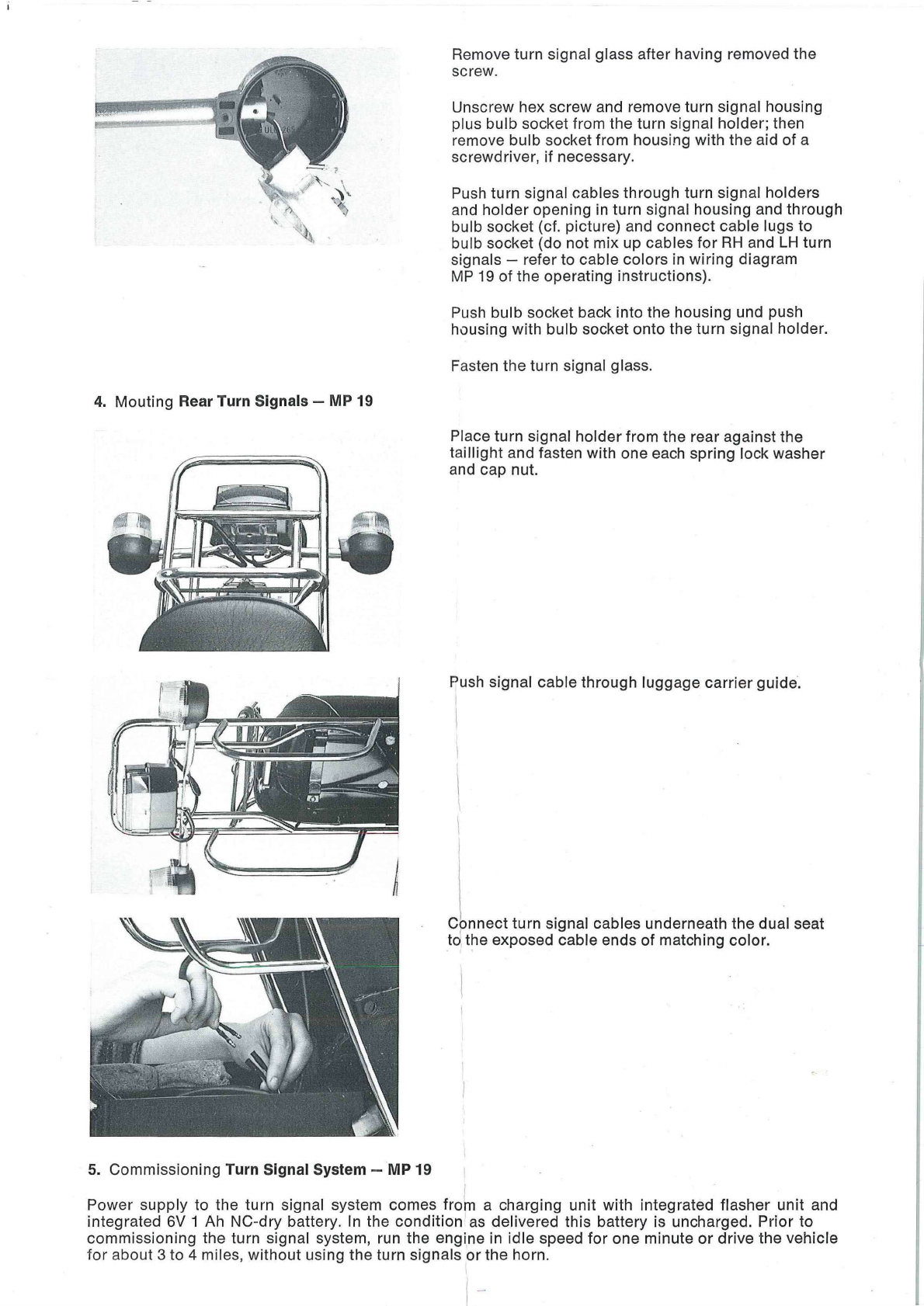
Push turn signal cables through turn signal holders
and holder opening in turn signal housing and through
bulb socket (cf. picture) and connect cable lugs to
bulb socket (do not mix up cables for RH and LH turn
signals — refer to cable colors in wiring diagram
MP 19 of the operating instructions).
Push bulb socket back into the housing und push
housing with bulb socket onto the turn signal holder.
Fasten the tum signal glass.
Place turn signal holder from the rear against the
taillight and fasten with one each spring lock washer
and cap nut.
Push signal cable through luggage carrier guide.
Connect turn signal cables underneath the dual seat
to the exposed cable ends of matching color.
4. Mouting Rear Turn Signals — WIP 19
5. Commissioning Tum Signal System — MP 19
Power supply to the turn signal system comes from a charging unit with integrated flasher unit and
integrated 6V 1 Ah NC-dry battery. In the condition as delivered this battery is uncharged. Prior to
commissioning the tum signal system, run the engine in idle speed for one minute or drive the vehicle
for about 3 to 4 miles, without using the turn signals or the horn.


 Supplementary service manual")


