Kremlin Cyclomix User manual

INSTRUCTION MANUAL
CYCLOMIXTM
CYCLOMIXTM PH
MIXING MACHINE
Manual : 0804 573.171.112
Date : 8/04/08 – Supersede : 9/01/06
Modif.: "Use the auto-wash" added (page 25)
KREMLIN REXSON – 150, avenue de Stalingrad
93 245 - STAINS CEDEX - FRANCE
Téléphone : 33 (0)1 49 40 25 25 Fax : 33 (0)1 48 26 07 16

KREMLIN Page 1 Manual : 573.171.112
SUMMARY
1. EC DECLARATION OF CONFORMITY ...................................................................................................... 2
2. GENERAL SAFETY INSTRUCTIONS......................................................................................................... 2
INSTALLATION REQUIREMENTS ............................................................................................ 2
EQUIPMENT REQUIREMENTS ................................................................................................ 3
MAINTENANCE REQUIREMENTS............................................................................................ 3
ENVIRONNMENT....................................................................................................................... 4
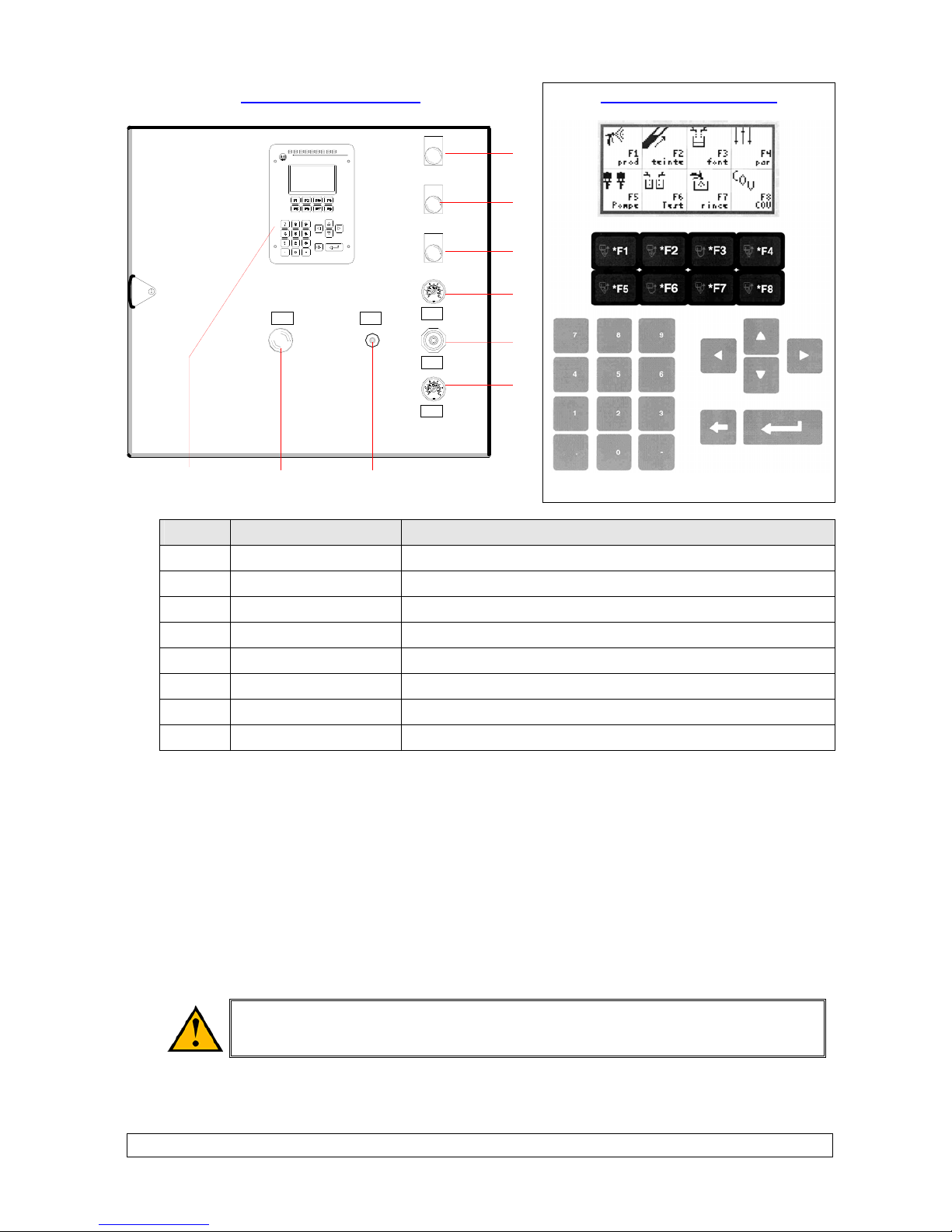
3. DESCRIPTION ............................................................................................................................................. 4
4. OPERATING PRINCIPLE ............................................................................................................................ 7
5. TECHNICAL FEATURES ............................................................................................................................ 8
6. INSTALLATION ........................................................................................................................................... 8
7. OPERATING .............................................................................................................................................. 10
DRIVING FROM THE MACHINE ............................................................................................. 10
SWITCHING ON THE MACHINE ............................................................................................. 10
8. FIRST SWITCHING ON ............................................................................................................................. 11
9. FIRST PLACING INTO OPERATION ........................................................................................................ 13
FLUSHING OF THE PUMPS AND OF THE MACHINE INTO SOLVENT ............................... 13
START-UP OF THE MACHINE ................................................................................................ 14
10. APPLICATION PROGRAMMING .............................................................................................................. 15
AUTHORIZATION..................................................................................................................... 16
LIST OF THE PARAMETERS .................................................................................................. 17
EXPLANATION OF THE PARAMETERS................................................................................. 18
GUN PRIMING.......................................................................................................................... 20
BASE FLUSHING ..................................................................................................................... 20
11. INDICATIONS GIVEN BY THE LED .......................................................................................................... 21
12. BATCH ....................................................................................................................................................... 21
13. TEST .......................................................................................................................................................... 21
14. WEEK-END FLUSHING OR PRODUCTION FLUSHING.......................................................................... 22
15. OTHER MENUS ......................................................................................................................................... 23
AUTOMATIC MENU ................................................................................................................. 23
AUTO-WASH MENU ................................................................................................................ 25
16. MAINTENANCE......................................................................................................................................... 27
17. TROUBLESHOOTING............................................................................................................................... 28
DIAGNOSTICS ......................................................................................................................... 29
18. DISASSEMBLY -REASSEMBLY ............................................................................................................. 33
MIXER....................................................................................................................................... 33
PILOTED VALVES (FLUID VALVES AND TEST VALVES)..................................................... 33
19. PREVENTIVE MAINTENANCE PLAN ...................................................................................................... 35
ADDITIONAL DOCUMENTS :
Annexes Pneumatic and electric diagrams
Mixing ratio chart
Doc. 573.171.120
Spare parts Cyclomix or Cyclomix PH Doc. 573.344.050 or Doc. 573.358.050
Color changer Doc. 573.188.050
Flow switch Doc. 573.320.050
AIRMIX filter Doc. 573.253.050

KREMLIN Page 2 Manual : 573.171.112
Dear Customer,
You are the owner of our new CYCLOMIXTM mixing machine and we would like to take this
opportunity to thank you.
To make sure your investment will provide full satisfaction, special care has been taken by
KREMLIN during all designing and manufacturing processes.
To obtain the best result, safe and efficient operation of your equipment, we advice you to read and
make yourself familiar with this instruction and service manual. Indeed, the non-compliance with
instructions and precautions stated in this manual could reduce the equipment working-life, result in
operating trouble and create unsafe conditions.
1. EC DECLARATION OF CONFORMITY
The manufacturer : KREMLIN REXSON with assets of 6 720 000 euros
Head office : 150, avenue de Stalingrad – 93 245 - STAINS CEDEX - FRANCE
Tel. 33 (0)1 49 40 25 25 - Fax : 33 (0)1 48 26 07 16
Herewith declares that : Two-component mixing machine is in conformity with the provisions of :
EC - Machinery directive (98/37/EEC Directive) and with national implementing legislation.
Established in Stains, on March 1st 2003,
Daniel TRAGUS
President
2. GENERAL SAFETY INSTRUCTIONS
The CYCLOMIXTM mixing machine shall be installed outside the explosive area. It
shall be in a safe area (non-explosive area according to the ATEX directive – refer to
§ 6)
WARNING : Any misuse of the equipment or accessories can damage them, result in serious body
injury, fire or explosion hazard and reduce the equipment working life. Read, understand and
comply with the safety instructions hereafter.
The personnel involved in operating and servicing this equipment must be aware of all safety
requirements stated in this manual. The workshop supervisor must be certain that the personnel has
perfectly understood the safety instructions and complies with them.
Read all instruction manuals as well as the tags of the equipments before operating the equipment.
Read local safety instructions and comply with them.
INSTALLATION REQUIREMENTS
ÂGround the equipment as well as the component to be painted.
Use the equipment only in a well-ventilated area to prevent from serious body injuries, fire and
explosion hazards. Do not smoke in the spray area.
Never stock paints and solvents in the spray area. Always close the pots and the tins.
Keep the spray area clean and free from debris (solvent, rags,…).

KREMLIN Page 3 Manual : 573.171.112
Read paint and solvent manufacturer's technical instructions.
Spraying of some materials may result in hazardous working conditions. To protect the operator,
respirator mask, hand cream and glasses are required (Refer to chapter "Safety equipment" of
KREMLIN selection guide).
EQUIPMENT REQUIREMENTS
The operating pressure of these equipments are particularly high. Consequently, some precautions
must be taken in order to prevent from accidents and from unsafe working conditions.
ÂNever exceed the components maximum working pressure of the equipment.
HOSES
Do not use hoses with a maximum burst-proof pressure less than four times the maximum service
pressure of the pump (see data sheet).
Be certain the hoses are not crimped, leaking and not unrolled.
Be certain hoses are in good conditions and showing no evidence of damage.
ÂUse only air hose with static conductor to connect the pump with the spray gun.
All fittings must be tight and in good condition.
PUMP
ÂGround the equipment (use the connection on the pump).
Do not use any product or solvent incompatible with the pump components.
Use the appropriate solvent for the material being sprayed to increase the equipment working life.
GUN
Never wipe the end of the tip with the fingers.
Always depressurize air and fluid hoses before carrying out any servicing on the gun.
Never point the spray gun at anyone or at any part of the body.
CYCLOMIXTM
ÂDo not install the machine in an explosive area. It shall be in a safe area (non-explosive
area).
ÂConnect the machine to a mains supply fitted with a ground.
Do not use any product or solvent incompatible with the machine components.
Use the appropriate solvent for the material being sprayed to increase the equipment working life.
ÂWear protective glasses to protect the operator from possible discharges during the
handling of the CYCLOMIX TM machine test outlets.
ÂDo not use electrostatic spraying for water-based paints or paints with a resistivity lower
than 10 MΩ.
MAINTENANCE REQUIREMENTS
ÂNever modify these equipments.
Check them daily, keep them in a good condition and replace the worn parts only with KREMLIN
parts.
Before cleaning or removing components of the equipment, it is compulsory :
1 - to stop the air supply,
2 - to open the gun fluid circuit to depressurize the hoses,
3 - to shut off the machine electrical supply,
4 - to open the drain valve.

KREMLIN Page 4 Manual : 573.171.112
ENVIRONNMENT
Label marking on the control box
(box located outside the spray booth)
This equipment consists of a label plate with the name of the manufacturer, the
equipment part number, the interesting informations to use correctly the
equipment (pressure, voltage…) and the above pictogram.
The equipment is designed with and consists of high quality materials and
components which can be re-used.
The 2002/96/EC European Directive covers all equipments with a crossed-out
bin pictogram. Please inform yourself about the collection systems for electric
and electronic equipments.
Please according to local rules and do not throw the old equipments with
household wastes. A correct disposal of the old equipment will help prevent
negative consequences for the environment and health.
3. DESCRIPTION
The CYCLOMIXTM mixing machine is designed for applying paints or two-component varnishes (solvent or
water-based).
It is available for 3 technologies of application : air spray, AIRMIX spraying, AIRLESS spraying
(maximum spraying : 200 bar / 2,900 psi).
It comes in an independent and moving form. It is only supplied with compressed air (maximum 6 bar / 87
psi) and with electricity (230 V).
It consists of : a frame, a control bay with automaton (PLC) and electropneumatic control components, a
module that receives the volumetric meters and the automatic valves for materials and solvents.

KREMLIN Page 5 Manual : 573.171.112
1
2
34
566
9
14
18
13 12
16
17
78 1110
15
21
19
20
22
23
IN 0
IN 1
24
25
1 Frame 14 Automatic valve
2 Control bay 15 Mixer
3 Screen 16 Test valve (TA & TB)
4 LED 17 Connecting support plate (inlets)
5 Air regulator 18 Connecting support plate (outlets)
6 Gauge 19 Mains supply unit (230V + T)
7 Automaton (PLC) 20 Cord grip (robot interface unit)
8 Supply 21 Cord grip (STD9 box supply)
9 Electrovalve 22 Beaker support (test valves)
10 Flowmeter 23 Beaker support (gun)
11 Pressure switch 24 Airmixfilter in line
12 Color changer 25 Air filters
13 Meter IN0 – IN1 : automaton (PLC) inlets

KREMLIN Page 6 Manual : 573.171.112
FRONT PART OF THE BAY
2
3
4
8
9
8
5+6 7
1
H
I
J
K
L
E
F
G
SCREEN AND KEYBOARD
Ind. Description Function
E Red LED Fault
F Orange LED Operating (except production)
G Green LED Production
H Gauge Reading of the spraying air pressure (gun)
I Air regulator Adjustment of the spraying air pressure (gun)
J Gauge Reading of the CYCLOMIXTM air supply pressure
K Black push-button Emergency flushing if electricity shut off
L Yellow push-button Function stopping
The machine is totally programmable via a man/machine interface. The screen indicates continuously, by
a simple identification, the statuses of the machine and the keyboard enables to have access to the
essential functionalities : ON / OFF - FLUSHING - PRODUCTION.
The informations relating to the operating of the machine (real-time display of the ratio, of the
consumption…) can be read on the LCD screen. The CYCLOMIXTM saves continuously the instantaneous
consumptions of base, catalyst and solvent as well as the total consumptions and the emissions of
Volatile Organic Compounds (VOC) during the operating of the machine.
On the right side of the machine, there is a cord grip. It is useful for the interface unit with the robot in the
situation of an automatic spraying.
On the left side of the machine, there is a cord grip. It is useful for supplying the STD9 box (115V / 230V),
in the situation of using an electrostatic gun.
Do not use electrostatic spraying for water-based paints or paints with a
resistivity lower than 10 MΩ.

KREMLIN Page 7 Manual : 573.171.112
4. OPERATING PRINCIPLE
The BASE and CATALYST materials are sent to the mixing machine from 2 pumps or pressure tanks.
Each material crosses a piloted valve, a meter. The cycle begins with the simultaneous opening of the
CATALYST and BASE valves. The 2 meters send their informations to the computer that shuts off the
catalyst valve when the computerized mixing ratio is reached.
The mixing process is based on a base constant flow. The catalyst flow is injected low in frequency and
regulated in pressure. The injection is made directly into the base flux at the mixer level.
The automaton (PLC) checks continuously the mixing ratio and if it notices a fault that it cannot correct, an
alarm is activated. The machine goes on safety mode.
SBB
VP4
VTA
CA
CB
ASA
VP6
VP2B VP3
VP1VP2A
MEL
VP1 Base solvent piloted valve (SA) VP5 Base test piloted valve
VP2B Catalyst piloted valve (B) VP6 Injection piloted valve
VP2A Base piloted valve (A) CA Base meter
VP3 Catalyst solvent piloted valve (SB) CB Catalyst meter
VP4 Catalyst test piloted valve MEL Mixer

KREMLIN Page 8 Manual : 573.171.112
5. TECHNICAL FEATURES
Number of colors : 1
Solvent and water-based paints compatibility
Possibility of automatic piloting via robot
Control external PLC
Batch
Different access levels to the software
Multilingual display
Display on the screen, in text form of the
machine operating, parameters, alarms and
faults
Mixing permanent check
Adjustable threshold alarm
Adjustable pot-life indicator
Automatic mixing control cycle
Automatic flushing cycle
VOC display
Total indicator for base , catalyst and solvent
consumption
Voltage : 230V / 115V – 75W
Minimum air pressure : 4 bar / 58 psi
Fluid pressure : from 2 to 200 bar/from 29 to 2900
psi
Weight : 65 kg / 143.26 lbs
Dimensions : 1380 mm x 640 mm x 480 mm
Stainless steel fluid circuit (Base and Catalyst) for
Cyclomix standard
316 L stainless steel fluid circuit (Catalyst) for
Cyclomix PH
Adjustable : from 0,6/1 to 20/1 (BASE volume /
CATALYST volume) (from 166% to 5%)
Measure precision : 1 %
Mixed fluid flow : from 50 to 1500 cm3/mn
Fluid viscosity : from 30 to 5000 cps
OPTIONAL :
Auto-wash
Remote control box
6. INSTALLATION
The CYCLOMIXTM mixing machine must be installed outside the spray booth.
Check the mains voltage and the voltage of the CYCLOMIXTM machine.
The CYCLOMIXTM must be connected to a clean and dry compressed air network (minimum 4 bar / 58 psi)
and to a single-phase electric supply (230 V / 115V).
ÂBefore connecting the CYCLOMIXTM, be certain the mains voltage is the same than the one of the
machine (230 V). If no, open the door of the bay and switch over the supply switch (ind. 8)
(230V Æ115V).
An air filter installed on the air supply of the machine equips the CYCLOMIXTM.
You will connect on the right of the frame on the
connecting support plate :
R1 (F 1/4 BSP) : compressed air supply hose
B (M 1/2 JIC) : CATA fluid hose
SB (M 1/2 JIC) : SOLVENT (CATA) hose
A (M 1/2 JIC) : BASE fluid hose
SA (M 1/2 JIC) : SOLVENT (BASE) hose
TB : CATA test valve outlet
TA : BASE test valve outlet

KREMLIN Page 9 Manual : 573.171.112
Connect the gun on the 2 outlets located on the plate
on the left (air and fluid supply).
R2 (F 1/4 BSP) : air hose
D (F 1/4 BSP) : mixed fluid hose
IN : return of the auto-wash pneumatic push-button
(cup)
R2
D
IN
Some Airmixin line filters are mounted on the "INLETS" connecting support plate : fluid and solvent of the
machine (A, B, SA and SB). In the standard version, # 6 screens come with filters. They must be adapted
to the material to be mixed and changed if necessary (refer to Spare parts).
B
A
Z1
Z2
Z2
1m
1m
1
2
3
4
5
8B
R1
B
SB
A
SA
6
6
77
A Explosive area : area 1 (Z1) or area 2 (Z2)
(spray booth)
4 BASE pump
B Non-explosive area (safe area) 5 SOLVENT pump (base)
1 CYCLOMIXTM mixing machine 6 Filter
2 CATA pump 7 Fluid pressure regulator
3 SOLVENT pump (cata) 8 Gun

KREMLIN Page 10 Manual : 573.171.112
Assemble filters at the outlet of the BASE and CATA pumps.
Assemble pressure regulators at the outlet of the BASE and CATA pumps.
Assemble fluid hoses and air hoses between the pumps and the CYCLOMIXTM, between the
CYCLOMIXTM and the gun. When choosing fluid hoses, respect the pressures delivered by the pumps.
For the air hoses, assemble antistatic hoses.
Unscrew all regulators before supplying air to the installation.
Shut off the test valves (TA & TB).
7. OPERATING
DRIVING FROM THE MACHINE
SCREEN
The different menus and the informations relating to the machine are displayed on the screen.
ÂRead carefully the messages and follow the instructions to operate the machine.
KEYBOARD
From F1 to F8 These keys control the different work phases of the CYCLOMIXTM
(refer to menus)
↵These keys enable the shift in the PARAMETER menu.
0 … 9 Digital keypad : these keys enable to enter the values of the parameters.
SWITCHING ON THE MACHINE
The placing of the system into operation requires that the BASE, CATALYST and
SOLVENT DRUMS are full enough to ensure the production.
Connect the gun before placing the system into operation.
Switch on the bay (switch located on the side of the bay).
Supply air to the CYCLOMIXTM bay (minimum 4 bar / 58 psi). The pressure can be read by means of the
gauge located on the front part of the bay.
Supply air to the air regulators of pumps (BASE, CATALYST, SOLVENT).
When switching on the bay, a menu is displayed on the screen.
Nota : Parameters have been programmed in the factory before the delivery of the machine. You must
adapt the parameters to the use. They must be modified by an authorized person (refer to list of
parameters).
This manual suits for next models
1
Table of contents