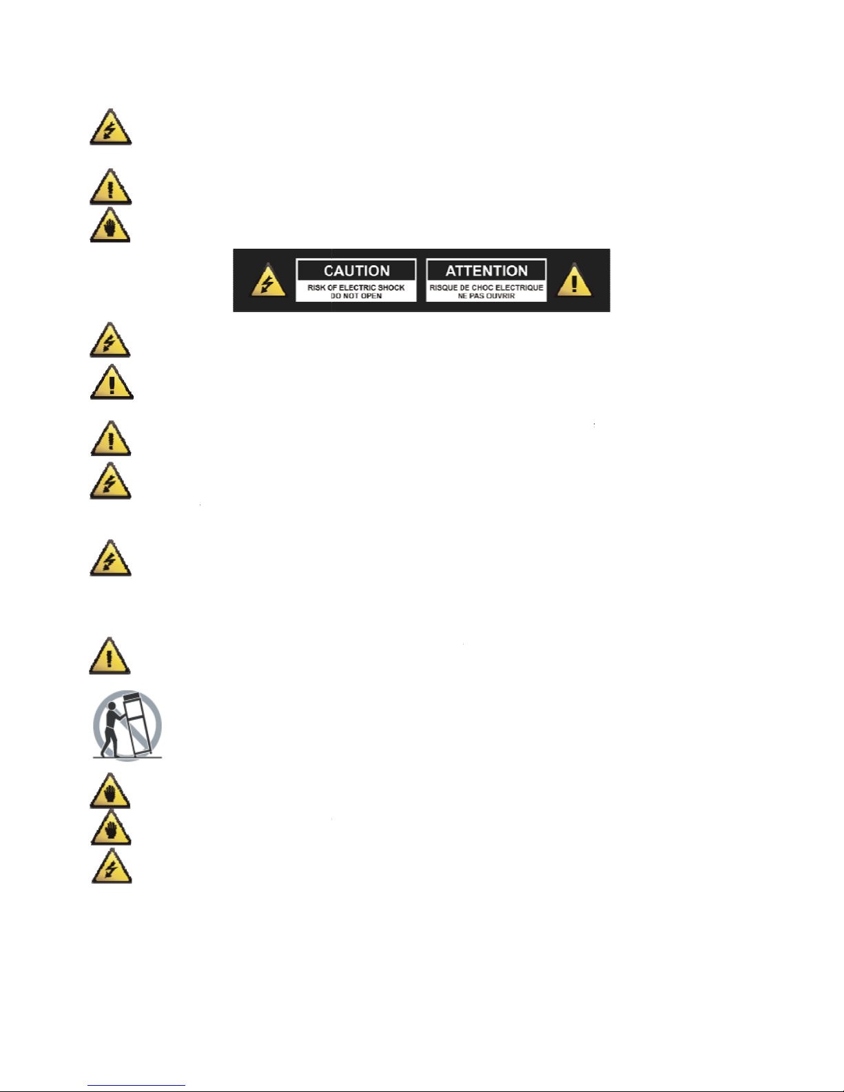
KRK 12sHO User manual

KRK12sHO SUBWOOFER
USER GUIDE
GUIDE D'UTILISATION
GUÍA DE USUARIO
Instruction Manual (English) – Page 1
Manuel d'instruction (français) – Page 22
Manual de instrucciones (español) – página 46

CAUTION: THE
USER TO THE P
R
MAGNITUDE TO
WARNING: TH
E
IMPORTANT OP
E
NOTE: THE HA
N
REGARDING TH
E
CAUTION: TO
R
ARE NO USER-
S
WARNING: RE
A
UNIT. RETAIN
T
READ AND FO
L
WARNING: Thi
s
harm.
CAUTION: To r
e
water; for exa
m
unit from the
w
always use a so
f
CAUTION: The
u
should not be s
i
installation, su
c
situated from h
e
naked flame so
u
WARNING: Do
injury to a child
manufacturer o
and
mo
v
ove
r
app
a
NOTE: Should t
disposal of elec
t
NOTE: KRK Sys
t
or the applicati
o
CAUTION TO P
R
ENGLISH:
T
GERMAN:
D
FRENCH:
L
SPANISH:
E
ITALIAN:
L
IMPORT
A
LIGHTNING FLASH WITH AN A
R
R
ESENCE OF UN-INSULATED DA
N
CONSTITUTE A RISK OF ELECTR
E
EXCLAMATION POINT WITHIN
E
RATING AND MAINTENANCE (
S
N
D WITHIN AN EQUILATERAL T
R
E
OPERATION OF THE UNIT, AN
D
R
EDUCE THE RISKS OF FIRE O
S
ERVICABLE PARTS INSIDE.
A
A
D AND FOLLOW ALL THE SA
T
HIS USER MANUAL FOR FU
T
L
LOWED.
s
product contains a chemical
k
e
duce the risks of fire or electri
c
m
ple, near a bath tub, washbo
w
w
all outlet before cleaning. Nev
f
t dry cloth. Unplug this produ
c
u
nit should be installed so tha
t
i
tuated on a bed, sofa, rug or s
i
c
h as a bookcase or cabinet, th
a
e
at sources such as radiators,
h
u
rces, such as lighted candles,
s
not place this unit on an unsta
or adult and serious damage t
r sold with the unit. Any moun
should use a mounting access
o
v
ed with care. Quick stops, exc
e
r
turn. Use only with the cart, st
a
ratus. When a cart is used, us
e
he unit become damaged bey
o
t
ronic products in your region.
t
ems, LLC cannot be held resp
o
o
ns provided for use with the
u
R
EVENT ELECTRIC SHOCK, M
A
T
he apparatus shall be connect
e
D
as Gerät ist eine Wandsteckd
o
L
'appareil doit être connecté à
u
E
l aparato estará conectado a u
L
'apparecchio deve essere colle
1
A
NT SAFETY I
N
R
ROWHEAD SYMBOL WITHIN A
N
GEROUS VOLTAGE WITHIN TH
IC SHOCK TO PERSONS.
AN EQUILATERAL TRIANGLE IS
S
ERVICING) INSTRUCTIONS IN
T
R
IANGLE IS INTENDED TO ALER
T
D
SHOULD BE READ FULLY BEF
O
R ELECTRIC SHOCK DO NOT
R
A
LL SERVICING SHOULD BE
R
FETY AND OPERATING INST
R
T
URE REFERENCE. ALL WAR
N
k
nown to the State of Californi
a
c
shock do not expose this pro
d
w
l, kitchen sink, laundry tub, in
er use thinner, cleaning fluids,
c
t during lightning storms or
w
t
its location or position does n
o
i
milar surface that may block t
h
a
t may impede the flow of air t
h
eat registers, stoves or other
d
s
hould be placed on, or near t
h
ble surface, cart, stand or trip
o
o the unit. Use only with a car
t
ting of the device on a wall or
o
ry recommended by the man
u
e
ssive force and uneven surfac
e
and, tripod, bracket, or table s
p
e
caution when moving the ca
r
o
nd repair, or reaches the end
o
o
nsible for damage, and, or incl
u
nit.
A
TCH WIDE BLADE OF PLUG
T
e
d to a Mains socket outlet wi
t
o
se mit einem Erdungsleiter an
u
ne prise secteur avec connexi
o
na toma de red eléctrica con u
n
gato a una presa di rete con u
n
N
STRUCTIONS
N EQUILATERAL TRIANGLE IS I
N
E UNITS ENCLOSURE THAT MA
Y
INTENDED TO ALERT THE USE
R
T
HE LITERATURE ACCOMPANYI
N
T
THE USER TO SPECIFIC GUIDA
N
O
RE USING THE UNIT FOR THE FI
R
EMOVE ANY COVERS, OR OP
R
EFERRED TO QUALIFIED SE
R
R
UCTIONS BEFORE CONNECT
I
N
INGS ON THE UNIT AND ITS
a
to cause cancer and birth de
f
d
uct to rain or moisture. Do no
t
a wet basement or near a swi
m
solvents or chemically impreg
w
hen unused for long periods o
f
o
t interfere with its proper ve
n
h
e ventilation openings; or pla
hrough its ventilation opening
d
evices (including amplifiers) t
h
h
e unit.
o
d, bracket or table. The unit m
t
, stand, tripod, bracket or tabl
e
ceiling should follow the man
u
u
facturer. An appliance and ca
r
e
s may cause the appliance an
d
p
ecified by the manufacturer,
o
r
t/apparatus combination to a
v
o
f its life, please consult the re
g
uding data loss caused by imp
T
O WIDE SLOT FULLY INSER
T
t
h a protective earthing conne
c
geschlossen werden.
o
n à la terre.
n
a conexión a tierra.
n
a connessione a terra protetti
v
N
TENDED TO ALERT THE
Y
BE OF SUFFICIENT
TO THE PRESENCE OF
N
G THE PRODUCT.
N
CE AND INFORMATION
RST TIME.
EN THE UNIT. THERE
R
VICE ENGINEERS.
I
NG OR USING THIS
PACKAGING SHOULD BE
fe
cts or other reproductive
t
use this product near
m
ming pool. Unplug the
nated cloths. For cleaning
f
time.
n
tilation. For example, it
ced in a built-in
s. The unit should be
h
at produce heat. No
ay fall, causing serious
e
recommended by the
u
facturer’s instructions
r
t combination should be
d
cart combination to
o
r sold with the
v
oid injury from tip-over.
g
ulations regarding
roper use of the unit and
T
.
c
tion.
v
a.

1. The unit and
casing.
2.Protect the p
o
exit from the a
p
3.Do not defeat
other. A groun
d
safety. If the pr
o
4.If the mains p
rupture value.
5.Never use a d
a
6.The power su
p
7. Only use atta
DO NOT ATTE
M
Upon completi
o
characteristics
a
equipment is in
REPLACEMEN
T
ATTENTION P
O
CORRESPOND
A
This unit sho
u
The power cord
Objects have fa
l
The unit has be
e
The unit does n
o
The device has
b
NOTE: Unplug
t
soft damp cloth
NOTE: Care sho
If an indoor ant
e
parts of other e
l
CAUTION – PO
IMPORT
A
power supply should only be c
o
wer cable from being walked
o
p
paratus.
the safety purpose of the pola
d
ing type plug has two blades
a
o
vided plug does not fit into y
o
lug supplying this product inc
o
a
maged or frayed power cable
;
p
ply cable of the unit should b
e
chments/accessories specified
M
PT SERVICING OF THIS UNI
T
o
n of any servicing or repairs, r
e
a
s the original parts have been
safe operating condition.
T
WITH UNAUTHORIZED PAR
T
O
UR …VITER LES CHOC ELEC
T
A
NTE DE LA PRISE ET POUSS
E
u
ld be serviced by qualified
or the plug has been damage
d
l
len, or liquid has been spilled
i
e
n exposed to rain or liquids o
f
o
t appear to operate normally
b
een dropped or the enclosure
t
he unit from the wall outlet b
e
.
uld be taken so that objects d
o
e
nna is used (either built into
t
l
ectrical appliances such as a l
a
WER LINES Any outdoor ante
n
2
A
NT SAFETY I
N
onnected to a power supply o
u
o
n or pinched particularly at p
l
rized or grounding-type plug.
A
a
nd a third grounding prong. T
o
ur outlet, consult a qualified e
o
rporates a fuse then it should
;
this can introduce serious ris
k
e
unplugged from the wall out
by the manufacturer.
T
YOURSELF. REFER SERVICI
N
e
quest the assurance that only
used, and that the routine saf
e
T
S MAY RESULT IN FIRE, ELE
T
RIQUES, INTRODUIRE LA L
A
E
R JUSQUíAU FOND.
service personnel when:
d
i
nto the unit
f
any kind
or exhibits a marked change i
n
damaged.
e
fore cleaning. Never use benz
e
o
not fall, and liquids are not s
p
t
he set or installed separately)
,
a
mp, TV set etc.
n
na must be located away fro
m
N
STRUCTIONS
u
tlet only of the voltage and fr
e
l
ugs, convenience receptacles,
A
polarized plug has two blad
e
he wide blade or the third pro
n
lectrician for replacement of t
h
only be replaced with a fuse o
f
k
of exposing lethal voltages.
let when it is to be unused for
N
G TO QUALIFIED SERVICE P
E
Factory Authorized Replacem
e
e
ty checks have been perform
e
CTRIC SHOCK OR OTHER HA
Z
A
ME LA PLUS LARGE DE LA FI
n
performance
e
ne, thinner or other solvents
f
p
illed into the enclosure throu
g
,
never allow any part of the a
n
m
all power lines.
e
quency marked on its
and the point where they
e
s with one wider than the
n
g is provided for your
h
e obsolete outlet.
f
identical or lower
a long period of time.
E
RSONNEL.
e
nt Parts with the same
e
d to guarantee that the
Z
ARDS.
CHE DANS LA BORNE
f
or cleaning. Use only a
g
h any openings.
n
tenna to touch the metal

OUTDOOR AN
T
system is groun
Electrical Code,
structure, grou
n
unit, connectio
n
a. Use No. 10 A
W
larger, as a gro
u
b. Secure anten
c. Mount anten
n
d. Use jumper
w
is used. see NE
C
EXAMPLE OF A
N
TELEVISION EQ
U
NOTE TO CATV
National Electri
c
be connected t
o
REGULATORY
C
conformity wit
h
The Declaration
Authorized Eur
o
IMPORT
A
T
ENNA GROUNDING If an outs
ded so as to provide some pro
t
ANSI/NFPA No. 70-1984, provi
n
ding of the lead-in wire to an
n
to grounding electrodes and
r
W
G (5.3mm
2
) copper, No. 8 A
W
u
nd wire.
na lead-in and ground wires t
o
n
a discharge unit as close as p
o
w
ire not smaller than No.6 AW
G
C
Section 810-21 (j).
N
TENNA GROUNDING AS PER N
A
U
IPMENT.
SYSTEM INSTALLER: This re
m
c
al Code that provides guideli
n
o
the grounding system of the
b
C
ERTIFICATION KRK declare u
n
h
the following standards:
s of Conformity can be obtain
e
o
pean representative: Phone:
+
3
A
NT SAFETY I
N
ide antenna is connected to y
o
t
ection against voltage surges
a
des information with respect t
antenna discharge unit, size o
f
r
equirements for the groundin
W
G (8.4mm
2
) aluminium, No. 1
7
o
house with stand-off insulat
o
o
ssible to where lead-in enters
G
(13.3mm
2
) copper, or the eq
u
A
TIONAL ELECTRICAL CODE INS
T
m
inder is provided to call the C
A
n
es for proper grounding and, i
n
b
uilding, as close to the point
o
n
der our sole responsibility th
a
e
d from 382 Ave. de la Couron
n
+
3226450500 Fax: +3264505
0
N
STRUCTIONS
o
ur tuner or tuner-preamplifier
a
nd built-up static charges. Ar
t
o proper grounding of the ma
s
f
grounding conductors, locati
o
g electrode.
7
AWG (1.0mm
2
) copper-clad
s
o
rs spaced from 4-6 feet (1.22
-
house.
u
ivalent, when a separate ante
T
RUCTIONS CONTAINED IN ART
I
A
TV system installers attention
n
particular, specifies that the
g
o
f cable entry as practical.
a
t this product, to which this d
e
n
e, B-1050 Brussles.
0
5
, be sure the antenna
t
icle 810 of the National
s
t and supporting
o
n of antenna discharge
s
teel or bronze wire, or
-
1.83 m) apart.
nna-grounding electrode
I
CLE 810 - RADIO AND
to Article 820-40 of the
g
round cable ground shall
e
claration relates, is in

4
World Class Performance in Studio Reference Monitors
KRK’s industry-leading line of studio monitors and subwoofers provide a level of precision and
performance unheard of in monitor systems. Your KRK12sHO subwoofer features several key design
elements that have come to be recognized as the “studio standard” for the world's finest engineers,
producers, and musicians. Your KRK subwoofer delivers world-class performance — at a price that makes
this a truly uncommon value.
Contents
Introduction 4
Unpacking 5
KRK Systems’ Design Philosophies 6
KRK’s ERGO Room Correction System 7
System Block Diagram 8
System Controls – Rear Panel 9
Connecting Your System 12
Subwoofer Placement and Set Up 14
Setting Subwoofer Levels 15
Hooking Up Your Subwoofer: 5.1 Surround 16
Bass Management Theory 17
Troubleshooting 18
Shipping Instructions 20
Specifications 21
Introduction
Congratulations and thank you for purchasing the KRK12sHO active studio subwoofer! We are the most
dedicated monitor company in the world and we are thrilled you have joined our ever growing family of
loyal customers. The KRK12sHO joins our premium subwoofer series, delivering an outstanding
performance, incredible accuracy, and high output level, again raising the bar above the competition.
We are not the new standard. We have always been the standard among the world’s finest engineers,
producers, musicians, and DJs.

5
The purpose of this manual is to explain the main features of the KRK12sHO and briefly describe its
operation. We encourage you to take a few minutes to familiarize yourself with the included information.
Thank you for choosing KRK!
Important notes:
Safety: To ensure correct operation of this product and for your own safety, please read the Important
Safety Instructions section.
Caution:
-Do not remove the rear panel of the subwoofer. It could result in electric shock. Refer to qualified
service personnel to perform any repair or service to the electronics.
-This product is capable of producing sounds at a volume that could cause permanent hearing
damage.
Unpacking
Your new subwoofer has been carefully inspected and tested prior to packing and shipping. After
unpacking your subwoofer, carefully inspect it for exterior damage and immediately report any physical
damage during transit to your shipping carrier. Save the shipping boxes and all packaging materials in
case the unit needs to be returned to your local dealer or KRK Systems, LLC.
•When you open the KRK12sHO carton, you will see that the subwoofer has been inverted so
you can fit the feet following the guide placed on top of the unit. Once this is completed, you
can return the product to its normal orientation for installation.
•Please ensure that you have fitted the type of feet required for the surface you intend to place
the subwoofer on. The KRK12sHO are supplied with rubber feet that are already screwed into
the M6 threads located on the bottom of the subwoofer.
•Ensure that the voltage indicator found in the voltage selector is set to the correct voltage
setting for your local supply.
Please read the warranty card that was included in the shipping carton with your product before shipping
to KRK Systems. A Return Material Authorization (RMA) from KRK Systems is required before shipping a
product to KRK Systems for repair. After obtaining a RMA from KRK Systems, all KRK Systems products in
need of repair can be returned to the dealer where they were purchased or sent directly to KRK Systems.
•For the safest possible return to KRK, please use the shipping carton and packaging materials
that were originally provided with your subwoofer.

6
•KRK cannot be responsible for any damages incurred during the shipping process due to poor
packing. Make certain to use insurance on your return shipment.
If your subwoofer is out of warranty and you would like a quotation before servicing your product, please
include a note with your contact information on it and we will contact you with a service quote. Service
will be performed once your method of payment has been established and approved.
KRK Systems’ Design Philosophies
Our Focus is Your Mix
At KRK, our focus has always been to make the most accurate studio monitors available at any price.
We don’t offer PA gear, mixers or motorcycles – just the tools you need to deliver a great mix. From the
legendary Exposé Series, to VXT to the new RoKit Generation 2 (“G2”) series – we know recording
monitors.
We do not add sonic characteristics like some other manufacturers that make their monitors appear to
provide more SPL or add low frequencies which may sound impressive to an untrained ear, but prevent a
competent engineer from making the right mix decisions.
When you use a KRK monitor, you can be confident that your mixes will translate well to the wide variety
of playback conditions that can occur in the real world. We want your audio mixes to sound good
everywhere – not just in your studio!
Port Design
Our ports are designed to greatly reduce air flow turbulence for high performance audio reproduction. The
result? Clear, accurate and well designed low frequency extension.
Even More Accurate than Before
We optimized our speaker voicing to provide even more accurate frequency response for transparent
audio reproduction using our custom made KRK drivers. What you hear is what you get, where ever your
music is being played. Our drivers are all custom-designed by our world-class studio monitor engineering
team.

7
KRK’s ERGO Room Correction System
We highly recommend use of the KRK ERGO room correction / audio interface for delivering the best
possible performance from your KRK monitoring system.
ERGO is a standalone, high-performance room correction system that allows you to use up to two
subwoofers with dedicated crossover functionality and delay compensation, and act as FireWire audio
interface with superb quality conversion.
For more information about using ERGO with your monitoring system, please visit our website at
http://www.krksys.com/product_ergo.php

System Bl
o
o
ck Diagram
8

9
System Controls – Rear Panel
Before installing and connecting the KRK12sHO, please read the System Controls descriptions so you are
familiar with the main concepts.
Figure 2.1 – System Controls on the Rear Panel
(1) INPUT SENSITIVITY
The input sensitivity should be adjusted to match the maximum audio output of the device that is
connected to the KRK12sHO input. Consult the instruction manual of the audio equipment, such as the
mixing console, that is connected to the input of the KRK12sHO.
(2) LOW-PASS FREQUENCY ADJUSTMENT
Low-Pass Frequency adjustment is performed through a continuously variable adjustment. The range is
from 60Hz to 160Hz. If you are using the Subwoofer Line Outs for the monitors, you will want to place this
at the 80Hz position so that the subwoofer only produces frequencies below this point. The Subwoofer

10
Line Outs have a fixed High Pass Filter (HPF) that passes only the mid and high frequencies above 80Hz to
the studio monitor.
(see additional information in the Connecting Your System section).
(3) PHASE ADJUSTMENT
The phase of the subwoofer can be fine tuned to adjust the phase of the subwoofer at the listening
position. A proper in-phase subwoofer will yield more bass than one that has not been adjusted. Be sure
the speaker is placed in an optimal location before making the final adjustments. (refer to the Setting
Subwoofer Levels section below).
(4) LFE INPUT
The LFE (Low-Frequency Effects/Enhancement) input is intended for a surround system with a channel
dedicated to low frequency sounds ranging from 3 Hz to 120 Hz. Ensure the Low-Pass Frequency
adjustment control is set to the LFE setting (fully clockwise).
(5) RIGHT & LEFT INPUTS - BALANCED
The RIGHT & LEFT inputs are connected to your audio equipment outputs, such as a mixing console, or
audio interface
(6) RIGHT & LEFT OUTPUTS - BALANCED
The RIGHT & LEFT outputs are connected to your studio monitors. The subwoofer outputs have a fixed
80Hz High Pass Filter(HPF) that removes low frequencies and passes only the mid and high frequencies to
the studio monitors.
(7) POLARITY
The polarity switch position of 0 or 180 degrees depends on a number of variables. These variables
include, the distance of the subwoofer from the listening position and monitors, as well as the system's
absolute polarity and the bass response of the room (refer to the Subwoofer Setup and Placement
section in order to determine the correct switch position for your monitoring system and room).
(8) LIMITER
The subwoofer contains a limiter circuit which provides improved protection. The default setting for this
switch will be in the OFF position. The limiter is designed to mitigate the negative effects of over driving
the amplifier and or the speaker’s driver. The limiter, when engaged to the ON position, can greatly
reduce the risk of harming a driver.
(9) GROUND LIFT
Engaging the ground lift switch can sometimes reduce ground loop noise in your system. By providing an
AC mains ground on the KRK12sHO and proper installation in a 'quiet studio' environment, the system is
happily quiet. However, noise will be induced if the monitor is installed in less than desirable settings (i.e.
audio cables run alongside power cables, behind refrigerators, near florescent lighting, older buildings
with bad wiring), or with certain equipment with lots of RFI (lap-top supplies, PCs, generator supplied AC

11
lines). This is because there is a ground loop through the sub panel, mains wiring, source, and back to the
subwoofer on Pin-1 of the Audio inputs. Ground currents traveling through this loop impose different
voltages along the path at different gain stages within the circuitry, thus creating noises.
The Ground lift switch does not affect the AC mains/panel safety ground. It does not 'open' the connection
thru Pin-1 to the panel, but increases the resistance (from zero ohms to one thousand ohms) to reduce
the ground current and induced noises. Safety is not affected.
Figure 2.2 – Bottom Section of the Rear Panel
(10) POWER SWITCH
The power On/Off switch is located on the rear panel. The triangle in the KRK logo on the rear plate
illuminates when power is applied.
(11) AC INPUT VOLTAGE SELECTOR
To change the AC Input Voltage, remove the power cord and slide the voltage selector to the desired
voltage setting. Please note that when making voltage changes, the fuses will have to be replaced (refer
to the Changing Fuses section below).
(12) AC INPUT INLET SOCKET
A standard IEC-type AC Inlet Socket is used to provide power to the subwoofer. Be sure to use the power
cord that is included with the product or one that is rated equal or greater than 240V, 15A.

12
(13) FUSE HOLDER
Under normal operation the fuses should not blow. A blown fuse usually indicates an overload or fault
condition. To change the fuse, remove the power cord, pry off the fuse block with a small flathead
screwdriver and change the blown fuses. Refer to the Specifications section for fuse current ratings.
NOTE: If the fuses blow immediately upon power up, this indicates a fault condition and the monitor
should be returned to KRK for repair.
(14) FOOTSWITCH
The footswitch connection is a bypass feature which allows the user to defeat the sub and provide full
range audio to your recording monitor in instances where the Line Outs are being utilized. This feature is
of great benefit in that the high-pass filter is bypassed allowing full bandwidth to run to the monitors
while muting the subwoofer. This allows the user to evaluate the impact of the subwoofer on the mix. The
KRK12sHO includes one KRK KFS-1 latching footswitch with LED indicator. For the LED indicator to be
utilized a ¼” TRS cable is required between the footswitch and the KRK12sHO. A ¼” TS cable can be used
with the KRK KFS-1 footswitch bypass feature with the exception that the LED indicator will not be
required.
Connecting Your System
IMPORTANT: Before starting up the subwoofer, be sure all connections are made, all fader
and controls should be set at their minimum levels, and all other equipment should be
powered prior to powering up your KRK12sHO subwoofer. If you are connecting the sub’s Line
Outs to your monitors, turn monitor power on after the subwoofer.
KRK subwoofers include a built-in crossover and amplifier, so you only need the appropriate hook up
cables to integrate it into your existing monitor system. First, you’ll need to connect a pair of cables from
the stereo monitor outputs of your console (or audio hardware device) to the left and right XLR or ¼”
input jacks on the subwoofer. Next, if you are using the internal 80 Hz high-pass filter built into the
subwoofer for the existing full-range monitors, hook the XLR output jacks on the subwoofer to the line-
level inputs of your full range monitors.
A more advance system is required if the preference is to not use the internal 80Hz high-pass filter. Such
advance systems would require the use of an external crossover. It is recommended to use an external
crossover that features a subwoofer output connection. Consult the external crossover user manual to
learn how to setup and connect the full range monitors and a subwoofer.

13
Subwoofer Hook Up with Active Monitors
If you are using active (powered) monitors, use an XLR or ¼” cable to connect the output of the subwoofer
directly to the input of the monitor. The output marked "Left" should go to your left monitor, and the
output marked "Right" should go to your right monitor.
Figure 3.1 – Subwoofer Hookup with Active Studio Monitors
Subwoofer Hook Up with Passive Monitors
If you are using passive (non-powered) monitors, use an XLR or ¼” cable to connect the output of the
subwoofer directly to the input of the monitor’s external power amplifier, and then connect the power
amplifier speaker output to the monitors.
Do not connect the speaker output of the monitor’s external amplifier to the input of the subwoofer. This
will cause permanent damage.
Figure 3.2 – Subwoofer Hookup with Passive Studio Monitors

14
Subwoofer Placement and Set Up
Note: A properly set up subwoofer system extends the bass response of the main stereo monitors down
into the 30-Hz range, but without exaggerating bass response in the room. Improper setup may cause an
exaggeration of bass response in the room, which in turn may cause the engineer to mix in less bass
energy than desired. We recommend paying close attention when configuring your subwoofer.
Bass frequencies are largely non-directional, however that does not mean that you should ignore the
subwoofer's placement in the room. If fact, a sub's physical position in the room in relation to the floor,
walls and other surfaces radically influences its bass response. In a monitoring situation, it is desirable to
place the subwoofer so that it produces the smoothest frequency response at the listening position. In
addition, since the subwoofer's output will interact with the other monitor speakers in the room, it is
important to consider the subwoofer and near-field speakers as a total system.
If you have access to a Real Time Analyzer and a calibration microphone, then setting up the room can be
fairly painless. There are good selections of iPhone/Smartphone applications which will allow your device
to measure SPL.
However, it can also be done with a generic SPL meter, or even your own ears, once you know what to
listen for.
What you are attempting to do is find a place in the room where the subwoofer interacts smoothly with
the acoustics to even out the bass response at the listening position. One way to do this is to reverse the
normal position of the subwoofer and listening spot by temporarily moving the subwoofer to your seat
position in front of the console. Then play back pink noise in the 30 to 80 Hz range or music with robust
bass information. Now by moving the SPL meter (or your ears) around the various potential speaker
positions in the room, you can listen for where the bass sounds the loudest. That is where the speaker
loading would potentially be at its greatest. Once you find the optimal spot, place the subwoofer at that
position and listen to it from the console position. Even without an SPL meter you can then use stepped
band-pass, pink noise and sine-wave sweeps to evaluate how even the bass response is. Move the
subwoofer around a foot at a time until the bass response is as even as possible at the listening position.

15
Figure 4.0 – Subwoofer Placement
Setting Subwoofer Levels
Once the stereo monitors and subwoofer are in position, their levels need to be matched. The process is
straightforward and is described below:
Obtain an SPL (Sound Pressure Level) meter, these are very cheap and are now commonly available as
Smartphone/iPhone applications. Set the low-pass filter on the subwoofer back plate to 80 Hz.
Send a one octave wide, band-pass pink noise signal to your monitoring system (the main speakers from
ERGO, or from the subwoofer if using the internal crossover). A good choice is 500 to 1,000 Hz band-
passed pink noise, which is within the fundamental frequency range of many vocalists, and minimizes
high-frequency problems but doesn't excite the subwoofer. Adjust your main monitors until you reach a
comfortable monitoring level. (Typically 85 decibels SPL using the C response curve on the SPL meter)
Next, route 1-octave, band-passed, bass pink noise to the subwoofer to the monitor system. A good noise
choice is 35 to 70 Hz, which is below the 80-Hz frequency of the subwoofer high-pass filter, but
sufficiently high enough that most subwoofers will have adequate response in that band. Set the gain of
the subwoofer level control until it matches the same 85-decibel SPL level. Then, turn up the low-pass
filter control on the subwoofer to 130 Hz. This allows the bass energy between the near-field speakers
and subwoofer to overlap.
Listen from the mix position and route pink noise with a band-pass of 80 Hz to 130 Hz to your monitoring
system. Have someone adjust the phase on the subwoofer (ideally a full 360 degrees), and then back, and
note the position which sounds loudest. The loudest position is correct and in phase. Now return the low-

16
pass filter to the 80-Hz position (or another frequency if you are using external high-pass filters for the
near-field speakers).
Your system should now be properly aligned for phase, level and spectral response.
Hooking Up Your Subwoofer: 5.1 Surround
This is a bit more involved than a stereo hook up since there are now six speakers involved— as well as
something called Bass Management (see the Bass Management Theory section). Notice in the figure
below that for professional use a separate 6-channel level control box is required between the mix-down
deck and the monitor speakers. This is because few small format mixing consoles have provisions to
switch and level-manage a 6-channel audio signal. The simplest and perhaps best way to accomplish this
is to use an external, 5.1 level controller. It is placed between the outputs of the mix-down deck and the
monitor speakers, allowing it to control the playback level while the mix-down deck receives full-level
recording signal.

17
Beyond Stereo to 5.1 Surround
When using a subwoofer for the LFE (Low Frequency Effects) channel in a 5.1 surround monitoring
system, rotate the low pass filter all the way to the right to the 170Hz position. Note that the LFE channel
is set with an additional 10dB of monitoring gain. To set this level, we recommend using 2-octave wide,
band-passed, pink noise from 20 to 80Hz for the LFE channel and 500 to 2,000Hz for the near-field
speakers. After adjusting each near-field monitor one at a time to 85dB SPL, adjust the LFE channel 10dB
louder to 95dB SPL.
Bass Management Theory
Bass management is a method for extending the bass response of small, near-field speakers used in 5.1
surrounds sound systems (familiarly called home-theatre systems). This is done by routing frequencies
below a cutoff point to a separate subwoofer (sometimes called “bass redirection” in home-theater
receivers). This can usually be enabled by selecting “Small Speakers” from a speaker set up menu. This
process places a group of two-way filters in the speaker output path, typically at 80Hz. These filters route
all sonic energy above this given frequency (e.g. 80Hz) to the Left, Center, Right, Left Surround and Right
Surround speakers. In turn, the process redirects the low-frequency energy from the five full-range
channels to a single subwoofer, which also reproduces the separate LFE channel.
Bass management is used in practically every consumer home-theater system. Therefore, audio engineers
mixing for modern listeners should realize that their studio monitoring systems must be able to reproduce
sufficient low frequencies so they can avoid recording undesirable subsonic information. Without such
studio monitoring, it is possible to release a mix with infrasonic problems, such as pops, air conditioner

18
rumble, traffic noise, footsteps, etc. These subsonic noises will be eliminated (masked) by the natural
high-pass filter effect of using near-field monitors with a response that goes down only as low as 40 or
50Hz. Thus, infrasonic problems may not be recognized (heard) in the studio. However, since virtually all
home-theatre systems use subwoofers with bass management, consumers will hear these infrasonic
problems at high volume levels in their home.
Bass management effectively extends the low-frequency response of near-field monitors down well into
the 25 to 40Hz range (depending on the subwoofer used). This allows the engineer to take evasive action
in the studio, such as engaging high-pass filters on input channels and microphones, adding pop filters
and suspension mounts to microphones and correcting HVAC and other rumble problems.
Troubleshooting
If you’re having trouble, check out these tips...
If there is no power, check to see if...
•The power cord is plugged into both the IEC socket on the rear panel of the unit and into the AC
mains.
•The AC mains voltage is matched to the operating voltage requirements. If the AC mains voltage is
higher than the selected voltage, it is possible that the fuse needs to be replaced.
•The power light is illuminated on the front panel of the monitor or on the back panel of the
subwoofer. Note that with the new RoKit series (Generation 2) or the VXT series, the logo illuminates
on the front panel to indicate that power is on. If the power indicator is not on, turn the power switch
off and check the A/C mains fuse(s).
•NEVER USE A LARGER AMPERAGE FUSE THAN IS SPECIFIED! See the Specifications section for the
correct fuse value. Turn the power switch back on. The power light should illuminate.
•Note: If a fuse change was needed (and the AV mains voltage is set correctly) yet upon powering the
unit back up the fuse(s) blow again, the product needs to be returned to the dealer you purchased it
from, or to KRK, for servicing.
If you can’t hear any sound...
•Repeat the steps in the Troubleshooting section above before continuing to the next steps.
•Check to see if all other audio devices using the same AC outlet are still operating.
•Make sure that:
•The audio source cable is plugged into both the source output and the unit’s input.
•The Input Sensitivity is set correctly.
•The signal source (e.g. mixing console, work station, CD player, etc.) is turned up to a level
that can properly send a signal to the monitors.

19
•If one of the full range monitors is working then exchange the audio input cable from the non-
working monitor to the working unit. This will determine whether it's really the monitor, a faulty
cable, or some other glitch in the audio chain.
•If the unit is still not responding, it should be returned to the dealer that you purchased it from, or to
KRK, for servicing.
If the monitor suddenly stops working...
•Turn the unit’s send down or off.
•Repeat the steps in the Troubleshooting sections above before continuing to the next steps.
•Carefully check to see if the amplifier's back plate is hot! If the unit has been running at highest
power output for an extended period of time, it could be that it has become overheated and the
protection circuitry has shut the system down momentarily. The unit provides maximum circuitry
protection against AC power surges, amplifier overdrive, and overheating of the amplifiers. Turn the
unit off then wait 30 minutes to allow the back plate to cool down. Turn the power switch back on.
•Increase the volume to check for normal operation.
•If the unit is still not responding, it should be returned to the dealer that you purchased it from, or to
KRK, for servicing.
The sound quality changes...
•Repeat the steps in the Troubleshooting section above before continuing to the next steps.
•Disconnect the signal cable at the unit’s input. With power on, place your ear close to each driver
(tweeter/woofer) and listen for noise (i.e. a slight hiss or hum). If there's absolutely no sound
whatsoever, it could be that one or more of the drivers (woofer, tweeter or both) is at fault. It's also
possible that the problem lies somewhere in the electronics.
•Play some non-distorted source material at a low volume. Carefully cover the tweeter (to block the
sound) without touching the diaphragm. Is the woofer producing a clean sound? If there is not a clear
tonal quality, or any sound at all, then the woofer probably needs to be replaced.
•Cover the woofer so you can hear mostly the tweeter. Is the tweeter producing a clear sound? If there
is not a clear tonal quality, or any sound at all, then the tweeter probably needs to be replaced.
•Once you have a better idea of what may be at fault then call us and speak with someone in the
service department. They will help you determine the best solution to correct your unit. The service
department can be reached at 954-949-9600.
The monitor (or subwoofer) hisses, hums or makes other loud noises...
Here are some suggestions that will help you eliminate these undesirables from your system:
•Make sure that the power cord is plugged snugly into the IEC socket on the rear of the unit.
•Check the connections between the signal source and the unit. The sub and monitor’s XLR and TRS
connectors are a completely balanced system. If you're connecting an unbalanced output to the
Other manuals for 12sHO
1
This manual suits for next models
1
Table of contents
Languages:
Other KRK Subwoofer manuals
Popular Subwoofer manuals by other brands

Sunfire
Sunfire SDS-8 quick start guide

Sound Sation
Sound Sation hyper bass series user manual

IMG STAGE LINE
IMG STAGE LINE PSUB-115AK instruction manual

Diamond Audio Technology
Diamond Audio Technology M5101 manual

Power bass
Power bass PS-DF110T Application guide

BASSFACE
BASSFACE IndyEVO10/2RK instruction manual