KROHNE USB ADAPTER PLUS User manual

Configuration tool for:
•IFC 100 / 300 (with Pactware)
•BATCHFLUX 5500 C (with BatchMon Plus)
•IFC 010 / 090 / 110 and BATCHFLUX 5012 C / 5015 C (with ImoMon Plus)
USB ADAPTER PLUS
USB ADAPTER PLUSUSB ADAPTER PLUS
USB ADAPTER PLUS Quick Start
Quick StartQuick Start
Quick Start
© KROHNE 06/2014 - 4003748601 - QS USB_Adapter_Plus R03 en

CONTENTS
2 www.krohne.com 06/2014 - 4003748601 - QS USB_Adapter_Plus R03 en
USB ADAPTER PLUS
1 General description 3
2 Operation 4
2.1 IFC 100 .............................................................................................................................. 4
2.2 IFC 300 .............................................................................................................................. 5
2.3 BATCHFLUX 5500 C.......................................................................................................... 6
2.4 Converters with ImoCom................................................................................................ 12
3 Notes 13

GENERAL DESCRIPTION 1
3
USB ADAPTER PLUS
www.krohne.com06/2014 - 4003748601 - QS USB_Adapter_Plus R03 en
The USB-Adapter Plus is an adapter to read / write all kind of data to many different converters.
The following overview shows you which parts and software you need:
The scope of delivery includes the USB-Adapter Plus, the cable needed for IFC 100 / 300 and the
printed documentation. Optionally you receive a set of connection cables / connectors for
connection to BATCHFLUX 5500 and old ImoCom type converters.
Signal converter Cable Software
IFC 100 and IFC 300 Standard cable dubox 2x3-pole > dubox 2x4-pole
or IR interface cable Pactware + DTM + GDC
drivers
BATCHFLUX 5500 C Optional cable M12 5-pole > dubox 2x4-pole
Optional T-connector M12 5-pole BatchMon Plus
BATCHFLUX 5500 C with
status output Optional cable M12 8-pole > dubox 2x4-pole
Optional T-connector M12 8-pole
Old ImoCom converters,
eg BATCHFLUX 5015,
IFC 010
Optional cable dubox 1x5-pole > 2x4-pole ImoMon Plus
2OPERATION
4
USB ADAPTER PLUS
www.krohne.com 06/2014 - 4003748601 - QS USB_Adapter_Plus R03 en
As described in the previous chapter, the USB-Adapter Plus can be used in three ways. Each way
is described in a separate section.
2.1 IFC 100
The standard delivery includes all items you need to use it with an IFC 100 signal converter.
Needed software:
•GDC driver
•IFC 100 HART DTM
•Pactware configuration tool
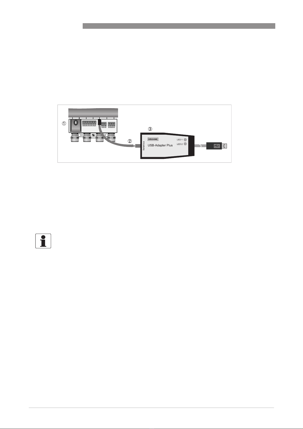
Figure 2-1: Connection of adapter to the GDC bus of the IFC 100.
1 Connection room of IFC 100
2 Cable 2x3-pole > 2x4-pole
3 USB-Adapter Plus
INFORMATION!
All relevant tools are on the CD and on the website of the manufacturer. Connect the USB
connector to your PC, start the relevant program and follow the instructions given on the display.
Refer to the documentation of the signal converter for a description of the menu.
OPERATION 2
5
USB ADAPTER PLUS
www.krohne.com06/2014 - 4003748601 - QS USB_Adapter_Plus R03 en
2.2 IFC 300
The standard delivery includes all items you need to use it with an IFC 300 signal converter.
Needed software:
•GDC driver
•IFC 300 HART DTM
•Pactware configuration tool
with GDC connection cable
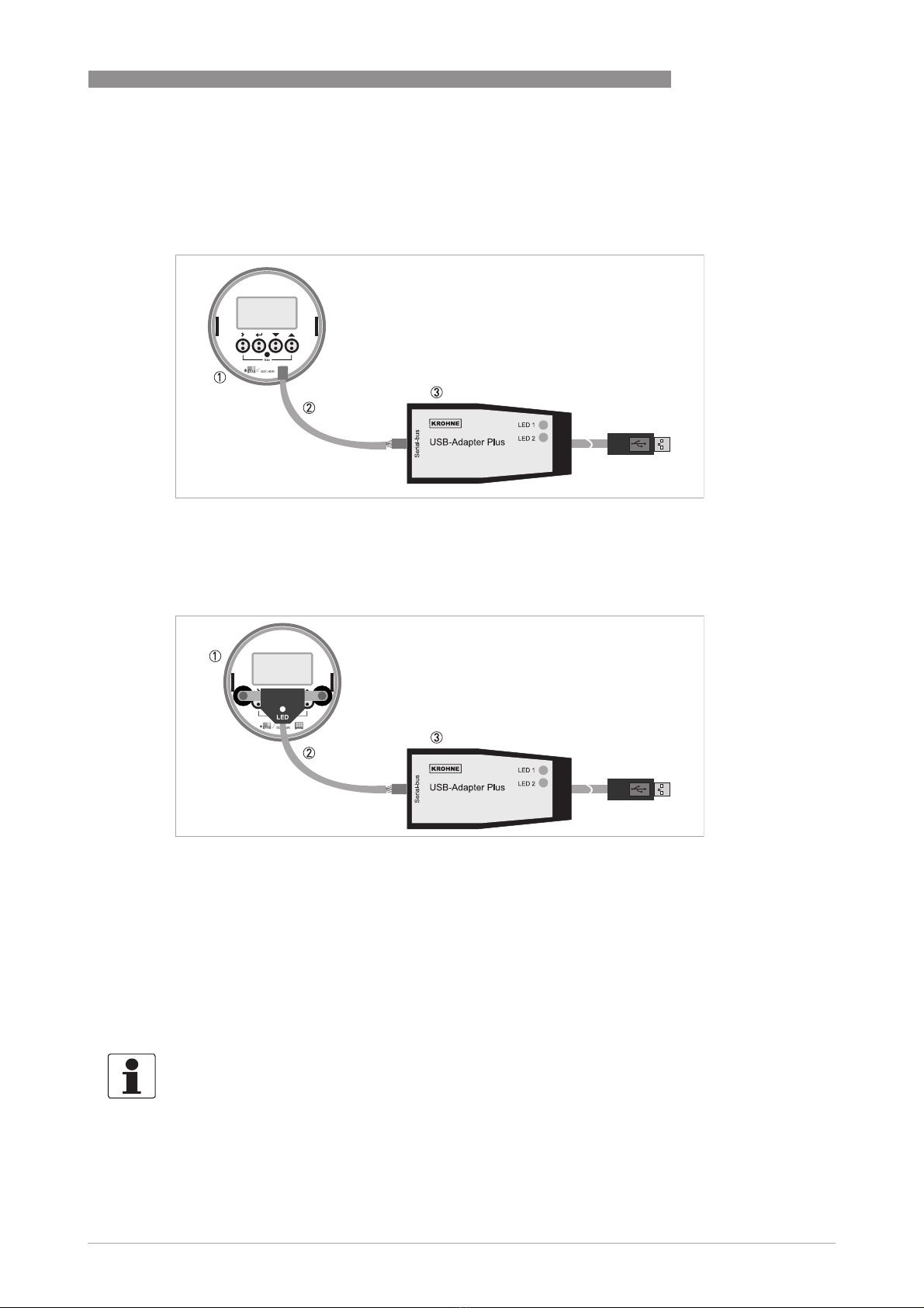
Figure 2-2: Connection of adapter to the GDC bus of the IFC 300.
1 Connection room of IFC 300
2 Cable 2x3-pole > 2x4-pole
3 USB-Adapter Plus
with IR interface cable
Figure 2-3: Connection of adapter to the IR interface of the IFC 300.
1 Display of IFC 300
2 IR Interface cable
3 USB-Adapter Plus
INFORMATION!
All relevant tools are on the CD and on the website of the manufacturer. Connect the USB
connector to your PC, start the relevant program and follow the instructions given on the display.
Refer to the documentation of the signal converter for a description of the menu.

2OPERATION
6
USB ADAPTER PLUS
www.krohne.com 06/2014 - 4003748601 - QS USB_Adapter_Plus R03 en
2.3 BATCHFLUX 5500 C
Needed software:
•BatchMon Plus
CAUTION!
The T-connectors and the cables ( M12 5-pole / 8-pole) are available as an optional package.
To order the specific cables notice the items 2, 3and 5in the illustration below
Figure 2-4: Connection of adapter to the BATCHFLUX 5500 C.
1 24 V supply (to be provided by customer)
2 T-connector (optional);
M12 5-pole
M12 8-pole (for BATCHFLUX 5500 C with status output)
3 BATCHFLUX 5500 C connector
M12 5-pole
M12 8-pole (for BATCHFLUX 5500 C with status output)
4 USB-Adapter Plus (standard)
5 Optional cable;
M12 5-pole -> 2x4-pole
M12 8-pole -> 2x4-pole (for BATCHFLUX 5500 C with status output)

OPERATION 2
7
USB ADAPTER PLUS
www.krohne.com06/2014 - 4003748601 - QS USB_Adapter_Plus R03 en
Installation procedure:
• Do NOT connect the USB adapter yet.
• Install the software KROHNE BatchMon Setup Version 3.x.x. Ignore any error messages about
Windows certificates.
• Connect the USB cable to the computer. The wizard "New hardware found" starts.
- Choose "Not now", click 1x on "Next".
- Screen "Hardware" opens, click 2x on "Continue".
- If hardware is detected, click on "Finish". Message shows "Hardware can be used".
• Start the BatchMon Plus program once. Close the program and start it again. In the menu, the
function "On-line processing" is now enabled.
The menu of the BATCHFLUX 5500 C is given on the next pages.
INFORMATION!
All relevant tools are on the website of the manufacturer.
INFORMATION!
Next time, just connect the USB-Adapter Plus and start the program.

2OPERATION
8
USB ADAPTER PLUS
www.krohne.com 06/2014 - 4003748601 - QS USB_Adapter_Plus R03 en
Menu C1: Process input
No. Function / subfunction Settings / descriptions
C1.1 Calibration
C1.1 Calibration
C1.1.1 Zero calibration Measured zero point (m/s).
Use the "calibration" button to calculate a new zero. Calibration procedure
takes 30 seconds.
C1.1.2 Size entry selection Value (mm), Table (mm, inch)
For "Value": manual input of flow meter size in box 1.1.3.
For "Table": choose from pull down menu in box 1.1.4.
C1.1.5 GK selection GK, GKL
For "GK": value is shown in box 1.1.6.
For "GKL": value is shown in box 1.1.7
C1.1.8 Coil resistance 10...220 Ω
Configured, can be changed.
C1.1.9 Field frequency 1/6...2 * line frequency
Choose from pull down menu.
1.1.10 Select settling Standard (predefined), Manual
1.1.11 Settling time 0,001...0,25 (s)
Manual input
1.1.12 Line frequency 50 or 60 Hz
1.1.13 Measurement conductivity Off, On
Off: Default
1.1.14 Number values 0...10
Number of measurements taken to calculate the average conductivity (if
1.1.13 is switched on).

OPERATION 2
9
USB ADAPTER PLUS
www.krohne.com06/2014 - 4003748601 - QS USB_Adapter_Plus R03 en
Menu C2: Inputs/outputs (I/O's)
C1.2 Filter
C1.2 Filter
C1.2.1 Min. limitation -100...-0,001 (m/s)
The output freezes at this value.
C1.2.2 Max. limitation 0,001...100 (m/s)
The output freezes at this value.
C1.2.3 Flow direction Normal direction (default), Reverse direction
C1.2.4 Time constant 0...100 (s)
Manual input
C1.2.5 Low flow cut off threshold 0...10 (m/s)
Manual input
C1.2.6 Low flow cut off
hysteresis 0...10 (m/s)
Manual input
C1.3 Information
C1.3 Information
No. Function / subfunction Settings / descriptions
C2.1 Hardware
C2.1.0 Hardware Frequency output, Pulse output
C2.1.1 Terminals D Program frequency output in submenu 2.2.0.1.
Program pulse output in submenu 2.2.0.2.
C2.2 Frequency output (if selected in 2.1.0 "hardware")
C2.2.1 Pulse shape Symmetric, Fixed, Automatic (default)
C2.2.2 Pulse width 5E-5...2 (s)
C2.2.3 100 % pulse rate 0,01…10000 (Hz)
C2.2.4 Range min. -1E+30...+1E+30 (m3/s)
Manual input.
C2.2.5 Range max. -1E+30...+1E+30 (m3/s)
Manual input.
C2.2.6 Polarity Both polarity, Positive polarity (default), Negative polarity, Absolute polarity
C2.2.7 Limitation min. -1E+30...+1E+30 (%)
C2.2.8 Limitation max. -1E+30...+1E+30 (%)
C2.2.9 Low flow cut off threshold 0...20 (%)
Manual input.
C2.2.10 Low flow cut off
hysteresis 0...20 (%)
Manual input.
C2.2.11 Time constant 0...100 (s)
C2.2.12 Invert signal Off (default), On

2OPERATION
10
USB ADAPTER PLUS
www.krohne.com 06/2014 - 4003748601 - QS USB_Adapter_Plus R03 en
Menu C3: Device
C2.2.17 Delay low flow cutoff 0...10 [s]
Manual input.
C2.2 Pulse output (if selected in 2.1.0 "hardware")
C2.2.1 Pulse shape Symmetric, Fixed, Automatic (default)
C2.2.2 Pulse width 5E-5...2 (s)
C2.2.6 Polarity Both polarity, Positive polarity (default), Negative polarity, Absolute polarity
C2.2.11 Time constant 0...100 (s)
C2.2.12 Invert signal Off (default), On
C2.2.13 Max. pulse rate 0,01...10000 (Hz)
C2.2.14 Value per pulse -1E+30...+1E+30 (m3)
C2.2.15 Low flow cut off threshold -1E+30...+1E+30 (m3/s)
Manual input
C2.2.16 Low flow cut off
hysteresis -1E+30...+1E+30 (m3/s)
Manual input
C2.2.17 Delay low flow cutoff 0...10 [s]
Manual input.
C2.3 Status output (not available in BATCHFLUX 5500 C Standard version)
C2.3.1 Mode Off, error, flow direction (default)
C2.3.2 Invert signal Off (default) , on
No. Function / subfunction Settings / descriptions
C3.1 Units
C3.1.1 Volume flow l/s, l/min, l/h, m3/s, m3/min, m3/h, ft3/s, ft3/min, ft3/h, gal/s, gal/min, gal/h,
lG/min, lG/h, free unit
When you choose "free unit" two additional boxes will appear: box 3.1.2 (text
free unit) and box 3.1.3 (m3/s * factor). With this factor the BATCHFLUX will
calculate the right value for your free unit.
C3.1.4 Volume ml, l, hl, m3, in3, ft3, yd3, gal, lG, free unit
When you choose free unit two additional boxes will appear: box 3.1.5 (text
free unit) and box 3.1.6 (m3* factor). With this factor the BATCHFLUX will
calculate the right value for your free unit.
C3.1.7 Flow speed ft/s, m/s (default)
No. Function / subfunction Settings / descriptions
Table of contents


