Krowne BS36 Installation instructions

Due to our commitment to continued product improvement, specications are subject to change without notice. No. REF MANUAL
Krowne Metal Corporation • 100 Haul Rd. Wayne, NJ 07470 • P: (800) 631-0442 • [email protected] • krowne.com
For Commercial Use Only. Not Residential.
Refrigeration
Installation & Operating Manual

2
Due to our commitment to continued product improvement, specications are subject to change without notice. No. REF MANUAL
Krowne Metal Corporation • 100 Haul Rd. Wayne, NJ 07470
Refrigeration
Installation & Operating Manual
krowne.com
Installation ............................................................................. 3
Operating Temperature and Defrosting .............................. 3
Thermostat.............................................................................. 4
Cleaning Instructions ............................................................ 4
Safety Notices....................................................................... 4
Specifications.................................................................... 5-6
Wire Diagrams.................................................................. 7-8
Replacement Parts: Compressor Housing........................... 9
Replacement Parts: Locks, Handles, & Doors ..............10-11
Replacement Parts: Mechanical & Lighting ...................... 12
Replacement Parts: Temperature Control .......................... 13
Replacement Parts: Shelving.............................................. 14
Direct Draw Coolers Parts & Accessories ......................... 15
Legs, Casters, Accessories..................................................16
Troubleshooting................................................................... 17
Changing a Door Handle.................................................. 18
Changing a Stainless Steel Top ......................................... 19
Changing a Swing Door ....................................................20
Changing Sliding Door ......................................................20
Changing LED Lights........................................................... 21
Adjusting Shelving .............................................................. 21
Warranty .............................................................................22
Terms ....................................................................................23
Table of Contents
Need replacement parts?
Refrigeration replacement parts available for all units.
Natural
Refrigerant
Natural Refrigerant
Hydrocarbon refrigerants are natural, nontoxic refrigerants
that are one of the most climate-friendly and cost-efcient
refrigerants with no ozone depleting properties.
partsbykrowne.com

3
Due to our commitment to continued product improvement, specications are subject to change without notice. No. REF MANUAL
Refrigeration
Installation & Operating Manual
Krowne Metal Corporation • 100 Haul Rd. Wayne, NJ 07470 krowne.com
Installation
Operating Temperature & Defrosting
SELF-CONTAINED UNITS:
Digital thermostat can be found on the front condensing unit cover. To set to desired temperature, follow the steps below.
1. Press SET for 1 second. The set value will start flashing after a few moments
2. Increase or decrease the value using UP or DOWN
3. Press SET to confirm new value
Manual defrost cycle: Press DOWN for more than 3 seconds
The operating temperature for the Self-Contained Back Bar Cooler is preset at the factory for an average of 35°F.
Average operating range is from 29°Fto 38°F.
Remote units need to be set by a certified refrigeration technician.
CAUTION:
This temperature is only a set point. If set to 32°F, product will not be 32°F and air temperature inside unit will not be 32°F.
Operating temperature/average temperature is usually 4°F to 5°F above set temperature.
Inspection Upon Receipt
Remove all shipping material from unit before operation.
Please inspect the unit for any hidden freight damage and
report any damage immediately to Krowne Metal Corp.
If included, install optional casters or legs to bottom of
unit. Please avoid turning unit on its side or rear to install
accessories. If this cannot be avoided, unit must be left in
the upright position for 24 hours before operating. All units
come equipped with predetermined mounting holes and self
starting bolts for easy install (bolts are provided only when
casters or legs are ordered from factory). It is important
to check that casters or legs are securely attached with
appropriate mounting hardware.
Electrical Requirements
115 Volt AC, 1 Phase, 60Hz. We recommend using a
dedicated 15 amp circuit minimum. 8’-0” grounded
cord standard on Self Contained Back Bar Coolers, Bottle
Coolers and Mug Frosters. Remote units come with a
terminal block inside the box for a hard wire connection
(supplied by the end user).
At Krowne Metal Corporation we are dedicated to customer satisfaction. This installation guide is provided to clarify and
answer any questions you may have regarding our line of Commercial Refrigerators. Please read this guide before attempting
installation or operation. Thank you for choosing Krowne as your refrigeration provider.
Plumbing
Self-Contained Back Bar Coolers have an evaporating pan
and do not require any plumbing hook-up. Remote units
require a drain hook-up. We recommend using 1/2” tubing
and running it through the same knockout used for the
refrigeration hook-up.
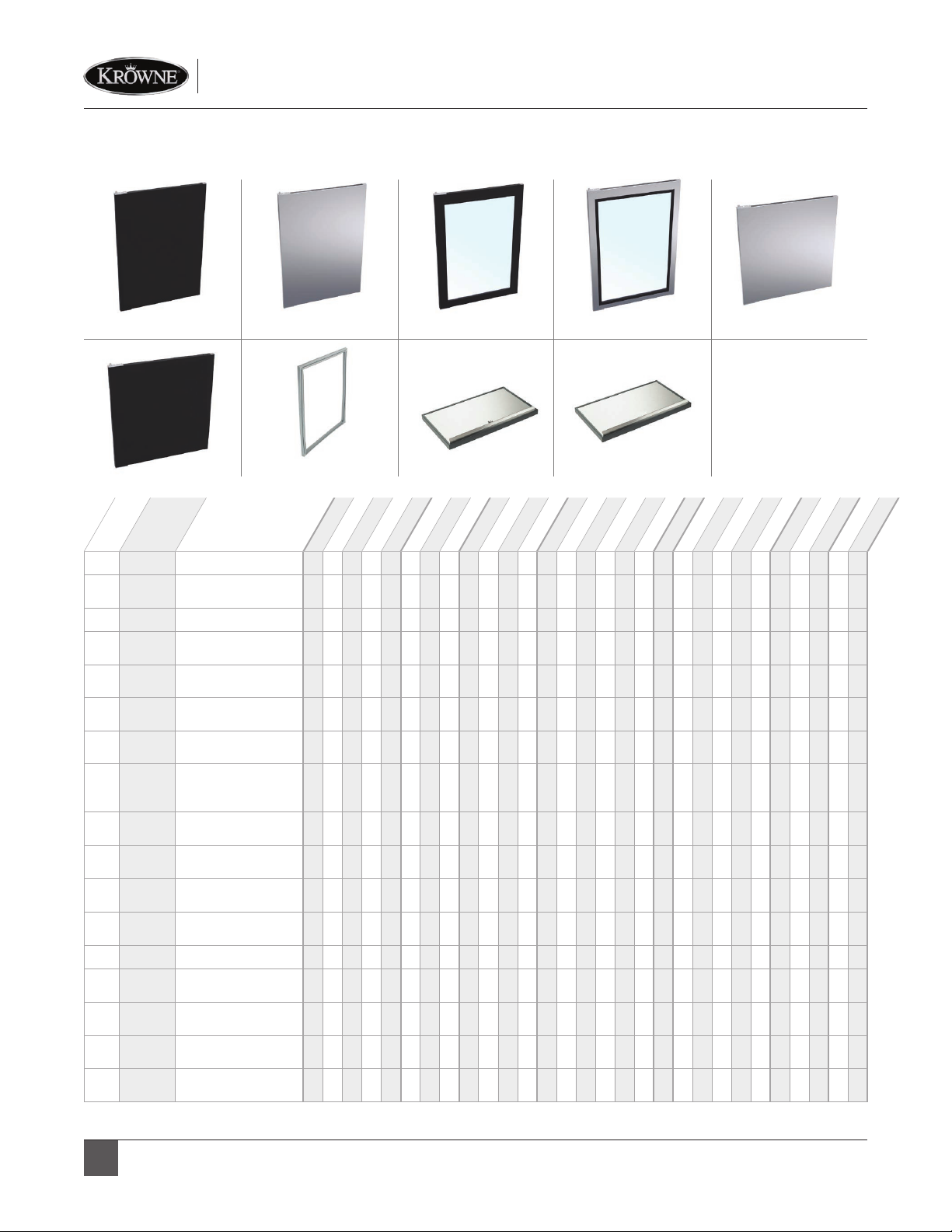
Installing of Shelves (Back Bar Coolers)
Shelves and installation clips are shipped within the cooler.
Shelves can be installed based on owner’s preference.
Location
Place unit in desired location and level. It is important for
the unit to be level, or it will not drain properly, and the
doors will not close properly, which in turn will affect the
function of the cooler and void any factory warranty. Allow
2” clearance for Back Bar Coolers in the back. If required,
unit can be sealed to oor using an NSF approved clear
silicone. Excess sealant should be wiped clean. DO NOT
BLOCK OR OBSTRUCT FRONT GRILL.

4
Due to our commitment to continued product improvement, specications are subject to change without notice. No. REF MANUAL
Krowne Metal Corporation • 100 Haul Rd. Wayne, NJ 07470
Refrigeration
Installation & Operating Manual
krowne.com
Make sure to avoid all products which may corrode the
stainless steel such as steel wool and chlorine based
bleaches. The cooler should be cleaned with a mild
detergent, warm water and a soft cloth. All cleaning
materials should be washed away and the cooler
completely dried.
DO NOT CLEAN WITH ANY BLEACH PRODUCTS Condenser must be cleaned every 60 days or may void
warranty. Prior to removing front panel on Back Bar Coolers,
you must shut off the unit (shut off switch is located next
to digital thermostat). Remove front grill for access to
condenser. If the condenser is not regularly cleaned, loss of
efciency and ultimately condenser failure may occur.
Doors as well as the interior of the cooler should be cleaned
occasionally to prevent buildup of liquids and other matter
that may interfere with operation. To clean these surfaces use
a mild detergent, warm water and a soft cloth. Dry completely!
DANGER: Risk of re or explosion. Flammable refrigerant
used. To be repaired only by trained service personnel.
Consult repair manual/owner’s guide before attempting
to service this product. Dispose of properly in accordance
with federal or local regulations. All safety precautions must
be followed. Do not puncture refrigerant tubing.
IMPORTANT: Keep clear of obstruction all ventilation
openings in the appliance enclosure or in the structure for
building-in.
IMPORTANT: Component parts shall be replaced with like
components. Servicing shall be done by factory authorized
service personnel, as to minimize the risk of possible ignition
due to incorrect parts or improper service.
Thermostat Key
Alarm Key
Code Alarm
E0 Box temperature probe error
E1 Evaporator defrost probe
DF Unit is running in defrost
Label Alarm
ADefrost ON/OFF LED
B* Fan ON/OFF LED
CCompressor ON/OFF LED
DTemperature Display (Avg. Inside Air Temp.)
EUP Button or HOLD for ON/OFF Compressor Power
FSET/MUTE Button
GDOWN Button or HOLD for Defrost Override
IMPORTANT: All service should be performed by a certied
refrigeration technician.
*B is only available on Mug Froster Congurations
Note:
All Mug Frosters have an evaporator coil defrost
every 4 hours and a full box defrost between
5 AM - 9AM daily. Time is preset at factory.
Below Notices apply to Hydrocarbon Refrigeration only (R290)
Thermostat
Cleaning Instructions
Safety Notices

5
Due to our commitment to continued product improvement, specications are subject to change without notice. No. REF MANUAL
Refrigeration
Installation & Operating Manual
Krowne Metal Corporation • 100 Haul Rd. Wayne, NJ 07470 krowne.com
Model No. BS36 BS60 BS84 BS108 NS52 NS72
Number of Doors 123423
Length 36” 60” 84” 108” 52” 72”
Depth 24” w/o Top
25” w/ Top
24” w/o Top
25” w/ Top
24” w/o Top
25” w/ Top
24” w/o Top
25” w/ Top
24” w/o Top
25” w/ Top
24” w/o Top
25” w/ Top
Refrigerant Type R290 R290 R290 R290 R290 R290
Charge 2.75 oz. 2.6 oz. 3.1 oz. 3.85 oz. 2.6 oz. 2.6 oz.
Design Pressure
H/L 450/130 450/130 450/130 450/130 450/130 450/130
H.P. 1/5 1/4 1/3 1/3 1/4 1/4
Full Load Amps 1.7 2.2 2.7 2.8 2.2 2.2
Case Capacity 7.0 15.7 24.5 30.0 12.0 19.0
Weight (lbs.) 285 360 480 525 300 420
Self-Contained
Back Bar Coolers
All units are 115V, 1 Phase, 60 Hz
Pass Thru
Back Bar Coolers
All units are 115V, 1 Phase, 60 Hz
Sliding Door
Back Bar Coolers
All units are 115V, 1 Phase, 60 Hz
Direct Draw Coolers
All units are 115V, 1 Phase, 60 Hz
Model No. SD60 SD108 PTSD60L
Number of Doors 244
Length 60” 108” 60”
Depth 25” 25” 26”
Refrigerant Type R290 R290 R290
Charge 2.6 oz. 3.85 oz. 2.6 oz.
Design Pressure H/L 450/130 450/130 450/130
H.P. 1/4 1/3 1/4
Full Load Amps 2.2 2.8 2.2
Case Capacity (12 oz. Bottles) 15.7 31 15.7
Weight (lbs.) 360 720 380
Model No. KPT36L KPT52L KPT60L KPT72L KPT84L
Number of Doors 24466
Length 36” 52” 60” 72” 84”
Depth 27-1/4” 27-1/4” 27-1/4” 27-1/4” 27-1/4”
Refrigerant Type R290 R290 R290 R290 R290
Charge 2.75 oz. 2.6 oz. 2.6 oz. 2.6 oz. 3.1 oz.
Design Pressure H/L 450/130 450/130 450/130 450/130 450/130
H.P. 1/5 1/4 1/4 1/4 1/3
Full Load Amps 1.7 2.2 2.2 2.2 2.7
Case Capacity (12 oz.
Bottles) 7.0 12.0 15.7 19.0 24.5
Weight (lbs.) 290 320 360 460 520
Model No. DB36 DB52 DB60 DB72 DB84 DB108
Number of Doors 122234
Length 36” 52” 60” 72” 84” 108”
Depth 25” 25” 25” 25” 25” 25”
Refrigerant Type R290 R290 R290 R290 R290 R290
Refrigerant Ounces 2.75 2.6 2.6 2.6 3.1 3.85
Design Pressure H/L 450/130 450/130 450/130 450/130 450/130 450/130
H.P. 1/5 1/4 1/4 1/4 1/3 1/3
Full Load Amps 1.7 2.2 2.2 2.2 2.7 2.8
Weight (lbs.) 285 300 360 420 480 525
Specifications

6
Due to our commitment to continued product improvement, specications are subject to change without notice. No. REF MANUAL
Krowne Metal Corporation • 100 Haul Rd. Wayne, NJ 07470
Refrigeration
Installation & Operating Manual
krowne.com
Model No. BR48 BR72 BR96
Number of Doors 234
Case Capacity 12 20 30
Length 48” 72” 96”
Depth 24” 24” 24”
Amps 1.0 (Lights and Fans) 1.5 (Lights and Fans) 2.0 (Lights and Fans)
Weight (lbs.) 280 395 510
Model No. MC24 MC36 MC48
Number of Doors 112
Length 24” 36” 48”
Depth 24” 24” 24”
Refrigerant Type R290 R290 R290
Layers of Shelving 222
Charge 3 oz. 3 oz. 3 oz.
Design Pressure H/L 450/130 450/130 450/130
H.P. 1/3 1/3 1/3
Full Load Amps 2.5 2.6 2.7
Mug Capacity 10. oz 95 165 240
Weight (lbs.) 185 240 295
Model No. FMC24
Number of Doors 1
Length 24”
Depth 24”
Refrigerant Type R290
Layers of Shelving 2
Charge 3 oz.
Design Pressure H/L 450/130
H.P. 1/3
Full Load Amps 2.5
Mug Capacity 10. oz 90
Weight (lbs.) 220
Model No. BC24 BC36 BC48 BC72 BC96
Number of Doors 11223
Length 24” 36” 48” 72” 96”
Depth 24” 24” 24” 24” 24”
Refrigerant Type R290 R290 R290 R290 R290
Divider Racks 11223
Charge 2.5 oz. 2.6 oz. 3 oz. 3 oz. 3.5 oz.
Design Pressure H/L 450/130 450/130 450/130 450/130 450/130
H.P. 1/5 1/5 1/4 1/4 1/3
Full Load Amps 1.53 1.53 2.18 2.53 2.71
Case Capacity (12 oz. Bottles) 6 9.5 15.5 25.5 37
Weight (lbs.) 185 240 295 410 455
Remote Back Bar Coolers
All units are 115V, 1 Phase, 60 Hz
Slide Top Mug Frosters
All units are 115V, 1 Phase, 60 Hz
Front Door Mug Frosters
All units are 115V, 1 Phase, 60 Hz
Bottle Coolers
All units are 115V, 1 Phase, 60 Hz

7
Due to our commitment to continued product improvement, specications are subject to change without notice. No. REF MANUAL
Refrigeration
Installation & Operating Manual
Krowne Metal Corporation • 100 Haul Rd. Wayne, NJ 07470 krowne.com
Model Description
BS36 36” Back Bar Cooler
BS60 36” Back Bar Cooler
BS84 36” Back Bar Cooler
BS108 36” Back Bar Cooler
DB36 36” Direct Draw Cooler
DB52 52” Direct Draw Cooler
DB60 60” Direct Draw Cooler
Model Description
DB72 72” Direct Draw Cooler
DB84 84” Direct Draw Cooler
DB108 108” Direct Draw Cooler
KPT36 36” Pass Thru Cooler
KPT52 52” Pass Thru Cooler
KPT60 60” Pass Thru Cooler
KPT72 72” Pass Thru Cooler
Model Description
KPT84 84” Pass Thru Cooler
NS52 52” Narrow Door Back Bar Cooler
NS72 72” Narrow Door Back Bar Cooler
PTSD60 60” Sliding Door Pass Thru Cooler
SD60 60” Sliding Door Back Bar Cooler
SD108 108” Sliding Door Back Bar Cooler
Model Description
BR48 48” Remote Back Bar Cooler
BR72 72” Remote Back Bar Cooler
BR96 96” Remote Back Bar Cooler
PLUG-IN-CORD
115 VOLTS 15 AMPS RECOMMENDED
TO THE CONDENSING UNIT
EVAPORATOR FAN MOTOR, 2 SPEED(BS36 BLACK
WIRE NOT CONNECTED TO RED (1 SPEED))
BLACK
WHITE
RED
BLACK
BLACK
BROWN BROWN
WHITE
RED BLACK
BLUE
LED LIGHTS
(2 PER DOOR)
RED (+DC)
BLACK (-DC)
12VDC
LED
POWER
SUPPLY
LIGHT SWITCH
TEMPERATURE
PROBE
8
9
7
6
4
3
DIGITAL
TEMPERATURE
CONTROL
PIN&SOCKET
CONNECTOR
4 WIRE FEMALE
RECEPTACLE
PIN&SOCKET
CONNECTOR
4 WIRE MALE PLUG
GROUND
POWER SWITCH 10
DEFROST PROBE
MULLION HEATER( 1 PER POST)
EVAPORATOR FAN MOTORS
(3 MOTORS 96" MODEL)
LED LIGHTS
(2 PER DOOR)
RED (+DC)
BLACK (-DC)
LED
12VDC
POWER
SUPPLY
LIGHT SWITCH
GROUND
115VAC
Note:
Field wiring to the cabinet
and from the cabinet to the
condensing unit must comply with
all local and electrical codes
BLACK
WHITE
GROUND
CONNECTION BLOCK
(right/left side of
evaporator housing
remove cover)
WHITE
BLACK
GREEN
PURPLE
SOLENOID
VALVE (IF USED)
RED
PIN & SOCKET CONNECTOR 4
WIRE FEMALE RECEPTACLE
PIN & SOCKET CONNECTOR 4
WIRE MALE PLUG
MECHANICAL
THERMOSTAT (IF USED)
RED
BLACK
WHITE
GREEN
Wire Diagrams

8
Due to our commitment to continued product improvement, specications are subject to change without notice. No. REF MANUAL
Krowne Metal Corporation • 100 Haul Rd. Wayne, NJ 07470
Refrigeration
Installation & Operating Manual
krowne.com
DIGITAL
TEMPERATURE
CONTROL
BOX
TEMP
SENSOR
TO THE CONDENSING
UNIT
(RED)
110V PLUG-IN CORD
POWER BLACK
NEUTRAL
WHITE
LIGHT CONNECTION
(OPTIONAL)
(WHITE)
(BLACK)
POWER
SWITCH
(BLACK)
EVAP
DEFROST
SENSOR
(BLUE) CENTER PIECE MULLION HEATER
(ONLY ON 48” UNITS)
FRAME MULLION HEATER
EVAPORATOR DEFROST HEATER
(RED)
(YELLOW)
(BLUE)
(WHITE)
EVAPORATOR FAN
(BLUE)
(BLACK)
(BROWN)
PLUG-IN-CORD
115 VOLTS 15 AMPS RECOMMENDED
TO THE CONDENSING UNIT
EVAPORATOR FAN MOTOR, 2 SPEED(2 MOTORS BC96
MODEL, BC24 AND BC36 MODELS BLACK WIRE NOT
CONNECTED TO RED (1 SPEED))
BLACK
WHITE
RED
BLACK
BROWN
WHITE BLUE
BLACK BLACK
TEMPERATURE
PROBE
8
9
7
6
4
3
DIGITAL
TEMPERATURE
CONTROL
PIN & SOCKET
CONNECTOR
4 WIRE FEMALE
RECEPTACLE
PIN & SOCKET
CONNECTOR
4 WIRE MALE PLUG
GROUND
BOTTLE COOLERS
1,2 AND 3 Door
POWER SWITCH 10
DEFROST PROBE
BROWN
LIGHT CONNECTION
(OPTIONAL)
Model Description
MC24 24” Slide Top Mug Froster
MC36 36” Slide Top Mug Froster
MC48 48” Slide Top Mug Froster
FMC24 24” Front Door Mug Froster
Model Description
BC24 24” Slide Top Bottle Cooler
BC36 36” Slide Top Bottle Cooler
BC48 48” Slide Top Bottle Cooler
BC72 72” Slide Top Bottle Cooler
BC96 96” Slide Top Bottle Cooler
Wire Diagrams

9
Due to our commitment to continued product improvement, specications are subject to change without notice. No. REF MANUAL
Refrigeration
Installation & Operating Manual
Krowne Metal Corporation • 100 Haul Rd. Wayne, NJ 07470 krowne.com
1A, 1B, 1C
4A, 4B
2
5
3
6A, 6B, 6C
1A BC-755 Compressor Head,
R290 (Propane) 1/6 HP
1B BC-756 Compressor Head,
R290 (Propane) 1/3 HP
1C BC-757 Compressor Head,
R290 (Propane) 1/4 HP
2 BC-668 Mug Froster
Accumulator Assembly
3 BC-669 Bottle Cooler
Accumulator Assembly
4A BC-766
Back Bar Accumulator
Assembly for Left
Side Compressors
4B BC-767
Back Bar Accumulator
Assembly for Right
Side Compressors
5 BC-772 Wire Harness Power
Supply
6A BC-670* Suction Line &
Cap Tube Assembly
6B BC-671* Suction Line &
Cap Tube Assembly
6C BC-683 Suction Line &
Cap Tube Assembly
No.
Model
Desc.
BC24
BC36
BC48
BC72
BC96
BS36
BS60
BS84
BS108
DB36
DB52
DB60
DB72
DB84
DB108
FMC24
KPT36L
KPT52L
KPT60L
KPT72L
KPT84L
MC24
MC36
MC48
NS52
NS72
PTSD60
SD60
SD108
*Note: When ordering BC-670 and BC-671, please specify the compressor side of your unit so correct part is shipped.
Replacement Parts - Compressor Housing

10
Due to our commitment to continued product improvement, specications are subject to change without notice. No. REF MANUAL
Krowne Metal Corporation • 100 Haul Rd. Wayne, NJ 07470
Refrigeration
Installation & Operating Manual
krowne.com
1A, 1B 2A, 2B
9A, 9B8A, 8B7A, 7B, 7C
3A, 3B 4A, 4B 5
6
Note: BC96 uses (2) 33” Sliding Doors (BC-712 or BC-713) and (1) 21” Sliding Door (BC-710 or BC-711)
1A BC-700 Black Vinyl Door
1B BC-694 Black Vinyl Door
(Narrow)
2A BC-701 Stainless Steel Door
2B BC-697 Stainless Steel Door
(Narrow)
3A BC-705 Glass Door with
Black Vinyl
3B BC-695 Glass Door with
Black Vinyl (Narrow)
4A BC-706 Glass Door with
Stainless Steel
4B BC-698
Glass Door with
Stainless Steel
(Narrow)
5 BC-715 Stainless Steel Door
for Mug Frosters
6 BC-716 Black Vinyl Door
for Mug Frosters
7A BC-552 Door Gasket for
Regular Doors
7B BC-553 Door Gasket for
Narrow Doors
7C BC-657 Door Gasket for FMC
8A BC-710 21” Sliding Door
with Lock
8B BC-712 33” Sliding Door
with Lock
9A BC-711 21” Sliding Door
(no lock)
9B BC-713 33” Sliding Door
(no lock)
No.
Model
Desc.
BC24
BC36
BC48
BC72
BC96
BR48
BR72
BR96
BS36
BS60
BS84
BS108
DB36
DB52
DB60
DB72
DB84
DB108
FMC24
KPT36L
KPT52L
KPT60L
KPT72L
KPT84L
MC24
MC36
MC48
NS52
NS72
Replacement Parts - Locks, Handles & Doors

11
Due to our commitment to continued product improvement, specications are subject to change without notice. No. REF MANUAL
Refrigeration
Installation & Operating Manual
Krowne Metal Corporation • 100 Haul Rd. Wayne, NJ 07470 krowne.com
10
16A, 16B
11 12 13
18
14
19
15
20
17A, 17B,
17C, 17D, 17E
Note: BC-590 - Bottom Door Hinge and BC-591 - Top Door Hinge (Spring Loaded) are included with doors.
10 BC-619
Door Lock Assembly
for Bottle Coolers &
Mug Frosters
11 BC-828 Back Bar Door
Handle Full Assembly
12 BC-789 Back Bar Door
Handle Lock
13 BC-816 Back Bar Door
Handle Top
14 BC-817 Back Bar Door
Handle Bottom
15 BC-830 Back Bar Door
Handle Tube
16A 1575 Top Door Support
Bracket
16B 1576 Top Door Support
Bracket (Narrow)
17A BC-608
24” Gasket for
Bottle Coolers &
Mug Frosters
17B BC-609
36” Gasket for
Bottle Coolers &
Mug Frosters
17C BC-610
48” Gasket for
Bottle Coolers &
Mug Frosters
17D BC-611
72” Gasket for
Bottle Coolers &
Mug Frosters
17E BC-612
96” Gasket for
Bottle Coolers &
Mug Frosters
18 BC-590 Bottom Door Hinge
19 BC-591 Top Door Hinge
(Spring Loaded)
20 BC-592 Zinc Plated
L-Bracket
No.
Model
Desc.
BC24
BC36
BC48
BC72
BC96
BR48
BR72
BR96
BS36
BS60
BS84
BS108
DB36
DB52
DB60
DB72
DB84
DB108
FMC24
KPT36L
KPT52L
KPT60L
KPT72L
KPT84L
MC24
MC36
MC48
NS52
NS72
Replacement Parts - Locks, Handles & Doors

12
Due to our commitment to continued product improvement, specications are subject to change without notice. No. REF MANUAL
Krowne Metal Corporation • 100 Haul Rd. Wayne, NJ 07470
Refrigeration
Installation & Operating Manual
krowne.com
1
5
2
6
3
7 8
4
1 BC-760 Fan Blade
2 BC-761* Fan Motor
3 BC-776 Fan Guard
4 BC-788 Evaporator Fan
Assembly
5 BC-774 LED Power Supply
6 BC-598 LED Converter
7A BC-814 Power Switch
7B BC-814 Light Switch
8 BC-100 Bottle Cooler LED
Interior Light Kit
9A 2164**
White LED Light
Assembly for
Standard Doors
9B 2165**
White LED Light
Assembly for
Narrow Doors
10 BC-823**
Warm White LED
Light Assembly
(3500K)
11 BS-500** Blue LED Light
Assembly
No.
Model
Desc.
BC24
BC36
BC48
BC72
BC96
BR48
BR72
BR96
BS36
BS60
BS84
BS108
DB36
DB52
DB60
DB72
DB84
DB108
FMC24
KPT36L
KPT52L
KPT60L
KPT72L
KPT84L
MC24
MC36
MC48
NS52
NS72
PTSD60
SD60
SD108
*Note: BC-761 is also used as an Evaporator motor for BC, FMC, and MC units.
**Note: Light Assemblies are designed on a per door basis. For example, a 2-Door unit requires (2) Light Assemblies.
9A, 9B 10 11
Replacement Parts - Mechanical & Lighting

13
Due to our commitment to continued product improvement, specications are subject to change without notice. No. REF MANUAL
Refrigeration
Installation & Operating Manual
Krowne Metal Corporation • 100 Haul Rd. Wayne, NJ 07470 krowne.com
1A, 1B
5A, 5B
2A, 2B
6
3A, 3B, 3C, 3D
7 8
4A, 4B
1A BC-557 Evaporator Coil
1B BC-558 Evaporator Coil
1C BC-519 Evaporator Coil
2A BC-630 Evaporator Coil
2B BC-502 Evaporator Coil
2C BC-503 Evaporator Coil
2D BC-504 Evaporator Coil
3A BC-505 Evaporator Coil
3B BC-506 Evaporator Coil
3C BC-507 Evaporator Coil
3D BC-822 Evaporator Coil
4A BC-513 Thermostat Sensor
for Mug Frosters
4B BC-537 Thermostat Sensor
for Back Bar
4C BC-517 Thermostat Sensor
(Long)
5A BC-509 Digital Thermostat
for Mug Frosters
5B BC-535 Digital Thermostat
6BC-655
Evaporator Defrost
Heater (Mug Frost-
ers)
7BC-627 Condenser Coil
8BC-642 Condenser Coil
No.
Model
Desc.
BC24
BC36
BC48
BC72
BC96
BR48
BR72
BR96
BS36
BS60
BS84
BS108
DB36
DB52
DB60
DB72
DB84
DB108
FMC24
KPT36L
KPT52L
KPT60L
KPT72L
KPT84L
MC24
MC36
MC48
NS52
NS72
PTSD60
SD60
SD108
Replacement Parts - Temperature Control

14
Due to our commitment to continued product improvement, specications are subject to change without notice. No. REF MANUAL
Krowne Metal Corporation • 100 Haul Rd. Wayne, NJ 07470
Refrigeration
Installation & Operating Manual
krowne.com
1A, 1B, 1C, 1D, 1E, 1F, 1G, 1H 4
2
5A, 5B, 5C, 5D
3
6A, 6B, 6C 7
1A BC-538 21-5/8” x 18” Shelf
1B BC-539 23-5/8” x 18” Shelf
1C BC-647 7” x 19-3/4” Shelf
1D BC-648 19-¼” x 19-¾” Shelf
1E BC-649 12” x 19-3/4” Shelf
1F BC-650 15” x 19-3/4” Shelf
1G BC-747 17-5/8” x 18” Shelf
1H BC-748 19-5/8” x 18” Shelf
2T22-0018 Pilaster (18”)
3 30-317 Pilaster Clip
4 BC-811 Side Guard Rail
5A BC-496 Shelf w/ Bottle
Dividers (L or R Door)
5B BC-497 Shelf w/ Bottle
Dividers (Center Door)
5C BC-485 Shelf w/ Bottle Dividers
(L or R Narrow Door)
5D BC-499 Shelf w/ Bottle Dividers
(Center Narrow Door)
6A BC-536 Wire Partition
6B BC-540 Wire Partition
6C BC-541 Wire Partition
7 BC-498* Back Bar Shelving Kit
No.
Model
Desc.
BC24
BC36
BC48
BC72
BC96
BR48
BR72
BR96
BS36
BS60
BS84
BS108
DB36
DB52
DB60
DB72
DB84
DB108
FMC24
KPT36L
KPT52L
KPT60L
KPT72L
KPT84L
MC24
MC36
MC48
NS52
NS72
PTSD60
SD60
SD108
*Note: BC-498 is a Back Bar Shelving Kit designed for Direct Draw Coolers in which one door section requires shelving.
The Kit contains 30-317 - Pilaster Clip (qty. 12), T22-0018 - Pliaster (18”) (qty. 4), BC-811 - Side Guard Rail (qty. 3), and shelves for the specied unit (qty. 3).
Replacement Parts - Shelving

15
Due to our commitment to continued product improvement, specications are subject to change without notice. No. REF MANUAL
Refrigeration
Installation & Operating Manual
Krowne Metal Corporation • 100 Haul Rd. Wayne, NJ 07470 krowne.com
1
7
13A, 13B
2
8
14
3
9
15
4
10
16
5A, 5B, 5C, 5D, 5E
11
17
6A, 6B
12A, 12B
18
1 BC-792 CO2 Tank Mount Primary Regulator
2 BC-793 CO2 Tank Mount Primary Bulk Regulator
3 BC-794 CO2 Tank Mount Primary Nitrogen Regulator
4 BC-843 CO2 Tank Mount Secondary Regulator
5A BC-795 2-Way Manifold
5B BC-796 3-Way Manifold
5C BC-797 4-Way Manifold
5D BC-798 5-Way Manifold
5E BC-799 6-Way Manifold
6A BC-800 Sankey Keg Tap, Stainless Steel Probe for Domestic Kegs
6B BC-800-S Sankey Keg Tap, Stainless Steel Probe for Import Kegs
7 BC-801 Beer Faucet Lock
8 BC-802 1/2” ID Clear Vinyl Drain Line (For Drip Pan Drain)
9 BC-803 5/16” ID Nylon Braided Air Line (Regulator to Manifold)
10 BC-804 5/16” ID Nylon Braided Air Line (Manifold to Keg Tap)
11 BC-805 Line Cleaning Kit
12A BC-300 Royal Series Standard Beer Faucet (Satin Finish)
12B BC-900 Royal Series Standard Beer Faucet (Stainless Finish)
13A BC-325 Royal Series Flow Control Beer Faucet (Satin Finish)
13B BC-925 Royal Series Flow Control Beer Faucet (Stainless Finish)
14 BC-806 Nitro Faucet, for Stouts and Coffee
15 BC-808 Wine Faucet with Long Spout
16 BC-812 Intertap Forward Sealing High-Performance Faucet
17 BC-824 Drain Container - 4 gallon capacity
18 BC-807 Standard Black Tap Handle
No.
Model
Desc.
DB36
DB52
DB60
DB72
DB84
DB108
Direct Draw Coolers Parts & Accessories

16
Due to our commitment to continued product improvement, specications are subject to change without notice. No. REF MANUAL
Krowne Metal Corporation • 100 Haul Rd. Wayne, NJ 07470
Refrigeration
Installation & Operating Manual
krowne.com
31
4
2
5
1A BS-100 6” Stainless Steel
Legs (Set of 4)
1B BS-101 6” Stainless Steel
Legs (Set of 6)
1C BS-102 4” Stainless Steel
Legs (Set of 4)
1D BS-103 4” Stainless Steel
Legs (Set of 6)
2A BC-130 2” Overall Casters
(1” Wheels, Set of 4)
2B BC-131 2” Overall Casters
(1” Wheels, Set of 6)
2C BC-132 3” Overall Casters
(2” Wheels, Set of 4)
2D BC-133 3” Overall Casters
(2” Wheels, Set of 6)
2E BC-134 4” Overall Casters
(3” Wheels, Set of 4)
2F BC-135 4” Overall Casters
(3” Wheels, Set of 6)
2G BC-136 5” Overall Casters
(4” Wheels, Set of 4)
2H BC-137 5” Overall Casters
(4” Wheels, Set of 6)
2I BC-138 6” Overall Casters
(5” Wheels, Set of 4)
2J BC-139 6” Overall Casters
(5” Wheels, Set of 6)
3 BD-101 Garnish Insert for
Drawers
4 BD-102 (3) Adjustable Wine
Dividers for Drawers
5 BC-111 Bottle Opener and
Cap Catcher
No.
Model
Desc.
BC24
BC36
BC48
BC72
BC96
BR48
BR72
BR96
BS36
BS60
BS84
BS108
DB36
DB52
DB60
DB72
DB84
DB108
FMC24
KPT36L
KPT52L
KPT60L
KPT72L
KPT84L
MC24
MC36
MC48
NS52
NS72
PTSD60
SD60
SD108
Legs & Casters Installation Note:
Avoid turning unit on its side or rear to install accessories.
If this cannot be avoided, unit must be left in the upright
position for 24 hours before operating. All units come
equipped with predetermined mounting holes and self
starting bolts for easy install (bolts are provided only when
casters or legs are ordered from factory). It is important
to check that casters or legs are securely attached with
appropriate mounting hardware.
Legs, Casters, and Accessories

17
Due to our commitment to continued product improvement, specications are subject to change without notice. No. REF MANUAL
Refrigeration
Installation & Operating Manual
Krowne Metal Corporation • 100 Haul Rd. Wayne, NJ 07470 krowne.com
Problem Cause Solution
There is no interior
light on in the
refrigeration unit.
Light switch is in OFF position. Flip switch to ON.
LED board is inoperable. Contact your dealer.
Refrigeration unit is
running noisy.
Soft sounds from compressor, fan motor
& valves. Normal operation.
Refrigeration unit is
not running correctly. No power is getting to the unit. GFI is tripped or the circuit breaker is tripped.
Reset the circuit breaker.
The compartments are
warmer than usual in
the refrigeration unit.
Control preset is not set properly. Reset preset temperature if necessary
Condenser is dirty or obstructed. Clean condenser and clear obstruction.
Door has been left open for an extended
period of time. Wait 24 hours and recheck temperature.
Internal louvers and/or fan guard obstructed. Ensure louvers and/or fan is not obstructed.
Warm product was placed in the unit. Remove warm product and wait 24 hours.
Refrigeration system
runs for long period
of time.
Condenser is dirty or obstructed. Clean condenser and clear obstruction.
Door has been left open for an extended
period of time. Wait 24 hours and recheck temperature.
Warm product was placed in the unit. Remove warm product and wait 24 hours.
Hot day and/or warm room temperature. Normal for system to run more frequently.
Condensation forms
on the inside of the
compartments.
High humidity and/or frequent door opening. Normal operation.
Door not closing and sealing properly.
Ensure door is closing properly. Check door
seals and replace if necessary. If condensation
persists, contact your dealer.
Condensation forms
on the outside of the
compartments.
High humidity and/or frequent door opening. Normal operation.
Door not closing and sealing properly.
Make sure door is closing properly. Check door
seals and replace if necessary. If condensation
persists, contact your dealer.
Before calling for service, please use this table to troubleshoot your issue.
Troubleshooting

18
Due to our commitment to continued product improvement, specications are subject to change without notice. No. REF MANUAL
Krowne Metal Corporation • 100 Haul Rd. Wayne, NJ 07470
Refrigeration
Installation & Operating Manual
krowne.com
Top Bracket
Handle Rod
Key Lock
Bottom Bracket
Tools Required: Phillips Head Screwdriver
1. Remove the eight 32 x 1/2” Phillips head screws located
on the top and bottom bracket of your existing door
handle. Remove the handle and set the screws aside.
These screws will be used on the new handle.
2. Assemble your new handle by sliding the handle rod into
the bottom bracket and top bracket.
3. Insert the lock at an angle into the slot on the backside
of the top bracket. Turn the lock counter clockwise until
it falls into place. Make sure the lock is positioned facing
down as pictured.
4. Position the new handle by aligning the top bracket with
the holes on the top of the door. Secure with existing
screws.
5. Align the bottom bracket with the holes on the side of
the door. Secure with existing screws. Repeat steps for
additional handles.
Changing a Door Handle

19
Due to our commitment to continued product improvement, specications are subject to change without notice. No. REF MANUAL
Refrigeration
Installation & Operating Manual
Krowne Metal Corporation • 100 Haul Rd. Wayne, NJ 07470 krowne.com
Tools Required: 1/4” Hex Screwdriver
2. Remove the 1/4” hex screws on the front of the unit
above the doors. Set the screws aside. These will be
used on the new refrigeration top.
4. Remove the 1/4” hex screws on the back of the unit.
Set the screws aside. These will be used on the new
refrigeration top.
3. Locate the 1/4” hex screws on the back of the unit.
5. With 2 or more people, lift the existing stainless steel top
off and set aside. Next, place the new stainless steel top
on your unit.
1. Locate the 1/4” hex screws on the front of the unit.
6. Secure the new top by screwing in the hex screws on the
back and front of the unit.
Changing a Stainless Steel Top

20
Due to our commitment to continued product improvement, specications are subject to change without notice. No. REF MANUAL
Krowne Metal Corporation • 100 Haul Rd. Wayne, NJ 07470
Refrigeration
Installation & Operating Manual
krowne.com
1. Locate hex screws on the
underside of the stainless steel
top and unscrew with a 1/4” hex
screwdriver. (Skip steps 1-3 if
your unit has an unnished top)
3. Once all hex screws are removed,
lift stainless steel top up to remove.
CAUTION: When the top is removed,
the door(s) should pull away and drop
rapidly. We recommend having 2 or
more people assist with this step.
2. Unscrew the (3) 3/8” hex screws
that are located on the top frame
of each door using a 3/8” hex
screwdriver.
1. Locate the spring on the top frame of
your refrigeration unit (See example
on top to see what spring looks like).
2. Insert the top half in,to the
frame. Make sure the spring
is pulled back with the door.
3. Apply pressure and push
the bottom half in until you
hear it snap into place.
4. For unfinished top units: Align new door with the bottom hinge
and re-screw the top (3) 3/8” hex bolts to secure the door.
For stainless steel top units: Align new door with the bottom
hinge and re-screw the top (3) 3/8” hex bolts to secure the door.
Place the stainless steel top back onto the unit and secure with
the 1/4” hex bolts.
Tools Required: 1/4” Hex Screwdriver & 3/8” Hex Screwdriver
Tools Required: None
Changing a Swing Door
Changing a Sliding Door
This manual suits for next models
31
Table of contents