kruss MKTV5 User manual

XFCAM1080PHB/PHD Auto Focus HDMI C-mount CMOS Camera
1/10
1 The XFCAM Camera Rear Cover Function
Figure 7 The Layout of XFCAM1080PHB/PHD Camera Rear Cover
The XFCAM1080PHB/PHD is a HDMI camera with auto focus function. Through the precise control of the
sensor position, the image can be focused automatically for the stereo or biological microscope. However, this
autofocus principle will destruct the microscope’s imaging conjugate principle and we think only a minor focus
adjustment can be made to keep the image with high quality.
But for the online basic observation, the XFCAM1080PHB/PHD camera can greatly increase the working
efficiency and eliminate manual focus operations.

XFCAM1080PHB/PHD Auto Focus HDMI C-mount CMOS Camera
2/10
2 Quick Instructions for XFCAM1080PHB/PHD camera
Before starting the camera please connect the standard XFCAM1080PHB/PHD C-mount camera to camera
adapter and connect it to the microscope’s 3rd tube which will relay microscope object’s middle image to the
camera sensor.
2.1 WiFi Mode
1. Plug 12V/ 1A power cable into Power Interface ③to supply power for the camera. The LED Indicator ⑥will
turn into red;
2. Press ON/ OFF Button ⑤to start the camera and the LED Indicator ⑥will turn into blue;
3. Plug the WiFi antenna which comes with the camera into WiFi ANTENNA/ USB PORT ②to generate WiFi signal;
4. After the indicator on the WiFi antenna starting blinking, connect computer (may be Pad or Phone) to WiFi
signal whose name starts with XFCAM1080PHB/PHD. The Password is 12345678;
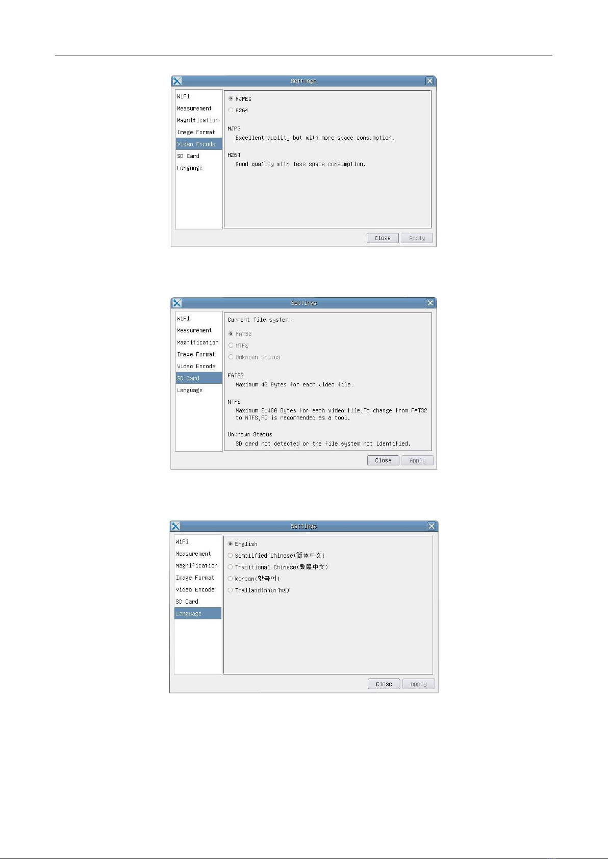
5. Open ImageView software, start XFCAM1080PHB/PHD by clicking the camera model name listed in Camera List.
For more details please refer to the ImageView help manual;
2.2 HDMI MODE
1. Plug the HDMI cable into the HDMI Port ①to connect the XFCAM1080PHD camera to HDMI display;
2. Plug a USB mouse into USB Port ②to get control of the camera by using built-in software XCamView;
3. Plug 12V/ 1A power adapter into Power Interface ③to supply power for the camera. The LED Indicator ⑥
will turn into red;
4. Insert SD card into SD Card Slot ④for saving captured images and recorded videos;
5. Press ON/ OFF Button ⑤to start the camera. LED Indicator ⑥will turn into blue;
6. Move mouse cursor to the left side of the video window, The Camera Control Panel will appear. It includes
Manual/ Automatic Exposure,White Balance,Sharpness,Denoise and other functions, please refer to 2.3 for
details;
7. Move the mouse cursor to the upper side of the video window, a Measurement Toolbar with calibration and
other measurement tools will appear, please refer to 2.3 for details; The measurement data can be output with
*.CSV format.
8. Move the mouse cursor to the bottom of the video window and a Synthesis Camera Control Toolbar will appear.
Operations like Zoom In,Zoom Out,Flip,Freeze,Cross Line,WDR and etc. can be realized. Please refer to 2.3 for
details;
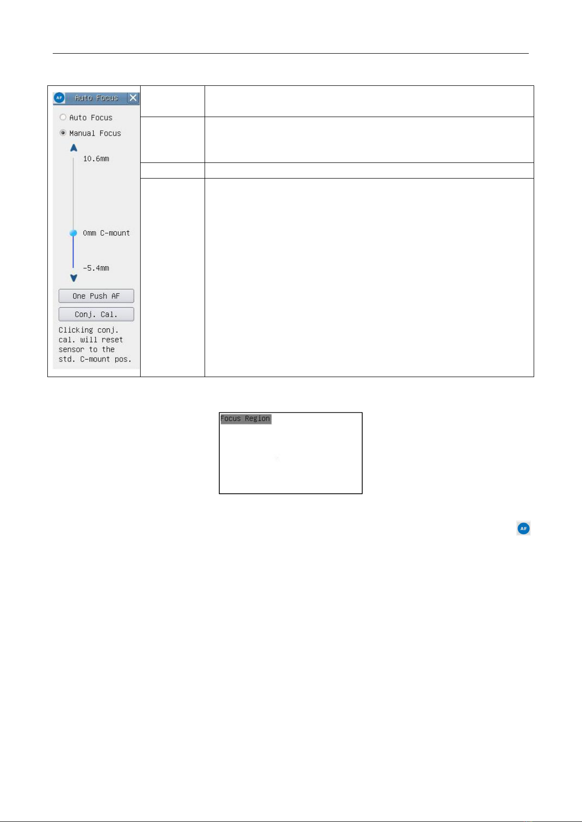
9. Move the mouse cursor to bottom of the video window, the Synthesis Camera Control Toolbar will pop up
automatically. Click the button and Auto Focus Control Panel will show up for conducting autofocus
operation;

XFCAM1080PHB/PHD Auto Focus HDMI C-mount CMOS Camera
3/10
2.3 Brief Introduction of XFCAM UI and Functions
The XFCAM UI shown in Fig. 8 includes the Camera Control Panel on the left side of the video window, the
Measurement Toolbar on the upper side of the video window, the Synthesis Camera Control Toolbar on the bottom of
the video window and the Auto Focus Control Panel on right side of the video window.
Figure 8 The XFCAM Camera Control UI
Notes
1
When users move the mouse cursor to the left side of the video window, the Camera Control Panel will pop up
automatically;
2
When users move the mouse cursor to the bottom of the video window, the Synthesis Camera Control Toolbar
will pop up automatically;
3
When user moves the mouse cursor to the bottom of the video window, the Synthesis Camera Control Toolbar
will pop up automatically. Click the button and the Auto Focus Control Panel will appear for autofocus
operation;
4
Move the mouse cursor to the upper side of the video window, the Measurement Toolbar will pop up for the
calibration and measurement operations. When user left-clicks the Float/Fixed button on the Measurement
Toolbar, the Measurement Toolbar will be fixed. In this case the Camera Control Panel will not pop up
automatically even if users move mouse cursor to left side of the video windows. Only when user left-clicks
the button on the Measurement Toolbar to exit from measuring procedure will they be able to do other
operations on the Camera Control Panel,Auto Focus Control Panel or Synthesis Camera Control Toolbar. During
the measuring process, when a specific measuring object is selected an Object Location & Attributes Control Bar
will appear for changing location and properties of the selected objects.

XFCAM1080PHB/PHD Auto Focus HDMI C-mount CMOS Camera
4/10
2.3.1 The Camera Control Panel on the Left Side of the Video Window
Camera Control Panel
Function
Function Description
Snap
Capture or Snap image from the current video window
Record
Record video from the current video window
Auto Exposure
When Automatic Exposure is checked, the system will automatically
adjusts exposure time according to the value of Exposure Compensation
value
Exposure
Compensation
Available when Auto Exposure is checked. Slide to left or right to adjust
Exposure Compensation according to current video brightness to
achieve proper brightness value
Exposure Time
Available when Auto Exposure is unchecked. Slide to left or right to
decrease or increase exposure time to adjust the video brightness
Gain
Adjust Gain to decrease or increase the video brightness. The noise will
be reduced or increased accordingly
Red
Slide to left or right to decrease or increase the proportion of Red in
video window
Green
Green is a base for reference and cannot be adjusted
Blue
Slide to left or right to decrease or increase the proportion of Blue for
the video
White Balance
Auto White Balance adjustment according to the window video
Sharpeness
Adjust Sharpness level of the video window
Denoise
Adjust Denoise level of the video window
Saturation
Adjust Saturation level of the video window
Gamma
Adjust Gamma level of the video. Slide to the right side to increase
gamma and to the left to decrease gamma
Contrast
Adjust Contrast level of the video. Slide to the right side to increase
contrast and to the left to decrease contrast
DC
For DC illumination, there will be no fluctuation in light source so no
need for compensating light flickering
AC(50HZ)
Check AC(50HZ) to eliminate flickering “strap” caused by 50Hz
illumination
AC(60HZ)
Check AC(60HZ) to eliminate flickering “strap” caused by 60Hz
illumination
Default
Set all the settings in the Camera Control Panel to the default values
The Camera Control Panel controls the camera to achieve the best image quality according to the specific
applications; It will pop up automatically when the mouse cursor is moved to the left side of the video window (in
measurement status, the Camera Control Panel will not pop up. Only when measurement process is terminated will
the Camera Control Panel pop up by moving mouse cursor to the left side of the video window). Left-clicking
button to achieve Display/ Auto Hide switch of the Camera Control Panel;

XFCAM1080PHB/PHD Auto Focus HDMI C-mount CMOS Camera
5/10
2.3.2 Icons and Functions of the Synthesis Camera Control Toolbar at the Bottom
of the Video Window
Icon
Function
Icon
Function
Zoom In the Video Window
Zoom Out the Video Window
Horizontal Flip
Vertical Flip
Video Freeze
Display Cross Line
WDR
Start Auto Focus Control Panel
Browse Images and Videos in the SD Card
Settings
Check Version of XCamView
The Setting function is relatively more complicated than the other functions. Here are more info about it:
Figure 9 Comprehensive Setting of WiFi Settings Page
Channel: WiFi signal Channel. Avoid interference caused by using the same channel. Suggest choosing different
channels for different cameras when several WiFi cameras are running at the same time;
SSID: Name of the WiFi signal. Can be user-defined by using the soft keyboard below;
Password:Password of the WiFi signal. The Password can be user-defined by using the soft keyboard below;
Default: Set Channel,SSID,Password to the default values;
Figure 10 Comprehensive Measurement Settings Page
Global:Used for setting digits behind the decimal point for measurement results;

XFCAM1080PHB/PHD Auto Focus HDMI C-mount CMOS Camera
6/10
Calibration Line Width: Used for defining width of the lines in measurement and calibration;
Color: Used for defining color of the lines in measurement and calibration;
EndPoint Type: Used for defining shape of the endpoints of lines in measurement and
calibration: Null means no endpoints, rectangle means rectangle type of endpoints.
It makes it easier to calibrate;
Point, Angle, Line, Horizontal Line, Vertical Line, Rectangle, Circle, Ellipse, Annulus, Two Circles, Polygon, Curve:
Left-click the besides the measuring patterns mentioned above will unfold the corresponding
attribute settings to set the individual property of the measuring objects.
Figure 11 Comprehensive Measuring Units, Calibration, Magnification Management Settings Page
Name: Names such as 4X, 10X, 20X ,40X , 100X are based on magnification of microscopes. For continuous zoom
microscopes, ensure that the selected magnification coincides with the scale alignment line;
Resolution: Pixels per meter. Devices like microscopes have high resolution value;
Clear All:Clear All the calibrated magnifications and resolutions;
Delete: Click Delete to delete the selected item for specific resolution;
Figure 12 Image Format Setting Page
JPEG:Save captured image in JPEG format into SD card;
TFT:Save captured image in TFT format into SD card. The TFT format saves not only image data but also the
measurement data over the image. The camera control & imaging processing software ToupView is capable of
opening TFT file;

XFCAM1080PHB/PHD Auto Focus HDMI C-mount CMOS Camera
7/10
Figure 13 Comprehensive Setting of Video Encode Setting Page
MJPEG:Save recorded videos in MJPEG coded format;
H264:Save recorded videos in H264 coded format;
Figure 14 Comprehensive Setting of SD Card Setting Page
Current File System: The maximum file FAT32 can store is of 4G Bytes; for NTFS it’s 2048G Bytes. Suggest converting
FAT32 file into NTFS format on a PC; Unknown Status: SD card not detected or the file system is not identified;
Figure 15 XFCAM Comprehensive Setting of Language Selection Setting Page
English:Set language of the whole software into English;
Simplified Chinese:Set language of the whole software into Simplified Chinese;
Traditional Chinese:Set language of the whole software into Traditional Chinese;
Korean: Set language of the whole software into Korean;

XFCAM1080PHB/PHD Auto Focus HDMI C-mount CMOS Camera
8/10
Thailand: Set language of the whole software into Thailand;
2.3.3 The Measurement Toolbar on the Upper Side of the Video Window
The Measurement Toolbar will pop up when moving mouse cursor to any place near the upper side of the video
window. Here are the introduction of the various functions on the Measurement Toolbar:
Figure 16 The Measurement Toolbar Button on the Upper Side of the Video window
Icon
Function
Float/ Fix switch of the Measurement Toolbar
Define measuring object in Show up/ Hide mode
Select the desired Measurement Unit
Choose the same Magnification as the microscope to ensure accuracy of measurement
result when measurement unit is not in Pixel unite
Object Select
Point
Angle
Arbitrary Line
Parallel
Horizontal Line
Vertical Line
Rectangle
Circle
Ellipse
Annulus
Two Circles and Center Distance
Arc

XFCAM1080PHB/PHD Auto Focus HDMI C-mount CMOS Camera
9/10
Polygon
Curve
Make Calibration to determine the corresponding relation between magnification and
resolution, this will establish the corresponding relationship between measurement unit and
the sensor pixel size. Calibration needs to be done with the help of a micrometer. For detailed
steps of carrying out calibration please refer to ToupView help manual.
Conjugate Correction: Click to do the Conjugate Correction before doing any
calibration. Then manually adjust the coarse and fine focus knob of microscope to make
sure the video is clear. Make sure the magnification in the software stays in accordance
with microscope magnification, and then select the corresponding Measurement Unit for
doing the measurement.
Export the measurement information to CSV file (*.csv)
Delete All the Measurement Objects
Setting
Exit from Current Measurement Mode
When the measurement ends, left-click on a single measuring object and the Object
Location & Properties Control Bar will show up. The icons on the control bar mean Move
Left,Move Right,Move Up,Move Down,Color Adjustment and Delete.
Note:
1) When user left-clicks Display/Hide button on the Measurement Toolbar, the Measurement Toolbar will be
fixed. In this case the Camera Control Panel will not pop up automatically even if moving mouse cursor to the left
side of the video window. Only when users left click the button on the Measurement Toolbar to exit from the
measurement mode will they be able to doing other operations in the Camera Control Panel, the Auto Focus Control
Panel or the Synthesis Camera Control Toolbar.
2) When a specific measuring object is selected during the measuring process, the Object Location & Attributes
Control Bar will appear for changing the object location and properties of the selected objects.
3) To ensure accuracy of the measurement, please click the Conjugate Correction button to reset the
camera sensor to the standard C-mount position before calibration. The measurements can be started after
calibration is completed and the video is focused.
4) In case calibration is completed but camera sensor is not on the C-mount position, The Conjugate Correction
should be done to reset sensor to the standard C-mount position and the video is focused before measurement is
started.

XFCAM1080PHB/PHD Auto Focus HDMI C-mount CMOS Camera
10 /10
2.3.4 Auto Focus Control Panel on the Right Side of the Video Window
Auto Focus
With Auto Focus button checked, the system will start autofocus according to
status of the specimen till it stays in focus;
Manual Focus
With Manual Focus checked, users should reset position of the camera
sensor by using the mouse to scroll up and down till the specimen stays in
focus;
One Push AF
Click One Push button can carry out autofocus operation for just once;
Conjugate
Correction
Left-click the Conjugate Correction button can reset the camera sensor to
standard C-mount position. Conjugate Correction allows users to get sensor
position calibrated while ensuring that the camera video window is clear as
well as image seen from eyepiece is clear. Suggest users do Conjugate
Correction when using the camera for the first time to ensure the camera
sensor at the standard C-mount position. This ensures the object plane,
eyepiece image plane and camera adapter image plane at the standard
position;
Note: 1) When height of the specimen changes, users must make sure the
sensor at the standard C-mount position while adjusting the coarse and fine
focus knob of microscope to focus; 2) Before doing measurement please do
Conjugate Correction to make sure accuracy of the measurement results
(please refer to Measurement Toolbar> Conjugate Correction... for details).
2.3.5 Focus Region in the Video Window
Figure 17 Focus Region
The Focus Region is used for selecting the region of interest for auto focus operation. When user clicks the
button on the Synthesis Camera Control Toolbar, the Focus Region will show up as well with the Auto Focus Control
Panel. Users can click any part of the video window to reset the focus region for Auto Focus operation.
When users close the Auto Focus Control Panel, the Focus Region will also be closed automatically.
Note: When Auto Focus is working, moving mouse cursor to upper side of the video window does not make
the Measurement Toolbar pop up.
This manual suits for next models
2
Table of contents