Installation
NOTE:
Please be cautious unpacking the battery, otherwise components could be damaged.
This Manual introduces the basic steps to install and set up Kstar BluE-H5/H3.
02
13
User Manual User Manual
NOTE:the voltage of a circuit which occurs continuously between any two live parts in the
worst-case rated operating condition when used as intended is DVC C
Any product damage or property loss caused by the following conditions, Kstar does not assume
any direct or indirect liability.
Product modi ed, design changed or parts replaced withoutfi authorization;Kstar
Changes, repair attempts and erasing of series number or seals by non technician;Kstar
System design and installation are not in compliance with standards and regulations;
Fail to comply with the local safety regulations (VDE for DE, SAA for AU);
Transport damage (including painting scratch caused by rubbing inside packaging
during shipping). A claim should be made directly to shipping or insurance company
in this case as soon as the container/packaging is unloaded and such damage is identi ed;fi
Fail to follow any/all of the user manual, the installation guide and the maintenance
regulations;
Improper use or misuse of the device;Insu cient ventilation of the device;ffi
The maintenance procedures relating to the product have not been followed to an
acceptable standard;
Force majeure (violent or stormy weather, lightning, overvoltage, re etc.);fi
Damages caused by any external factors.
1.8 Liability Limitation
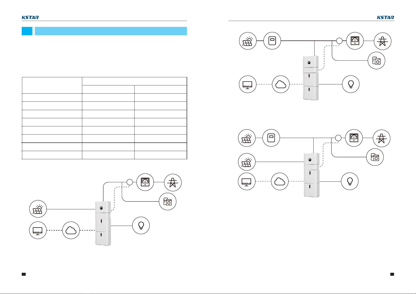
2.1.1 General
This H5/H3 energy storage system shall be installed in indoor location or outdoor
unconditioned without solar e ect location.ff
When H5/H3 systems are installed in a room,H5/H3 must not be hampered by the
structure of the building, the furnishings and equipment of the room.
The H5/H3 is naturally ventilated. The location should therefore be clean, dry and
adequately ventilated. The mounting location must allow free access to the unit for
installation and maintenance purposes, and the system panels must not be blocked.
The following locations are not allowed for installation:
The H5/H3 shall not be installed :
(a) in restricted locations as de ned for panels in AS / NZS 3000;fi
(b) within 600mm of any heat source, such as hot water unit, gas heater, air conditioning
unit or any other appliance.
(c) within 600mm of any exit;
(d) within 600mm of any window or ventilation opening;
(e) within 900mm of access to 240Vac connections;
(f) within 600mm of side of other device.
2.1.2 Restricted Locations
Habitable rooms;
Ceiling cavities or wall cavities;
On roofs that are not speci cally considered suitable;fi
Access / exit areas or under stairs / access walkways;
Where the freezing point can be reached, such as garages, carports or other places as
well as wet rooms (environmental category 2);
Locations with humidity and condensation over 90%;
Places where salty and humid air can penetrate;
Seismic areas - additional security measures are required;
Sites with altitude below 2000m;
Places with an explosive atmosphere;
Locations with direct sunlight or a large change in the ambient temperature;
Places with ammable materials or gases or an explosive atmosphere.fl
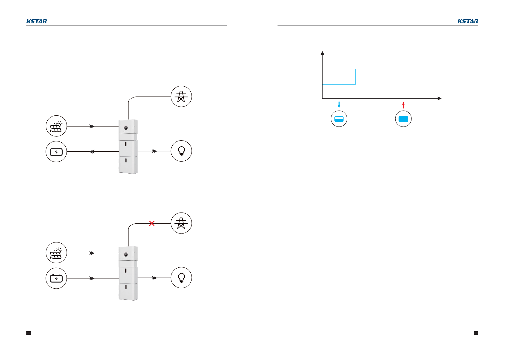
This unit shall only connect to grid as single inverter. Two or more in parallel or three
combination as three-phase, are not allowed. The installation of single phase is 5kVA
maximum.
2.1 Installation Site and Environment
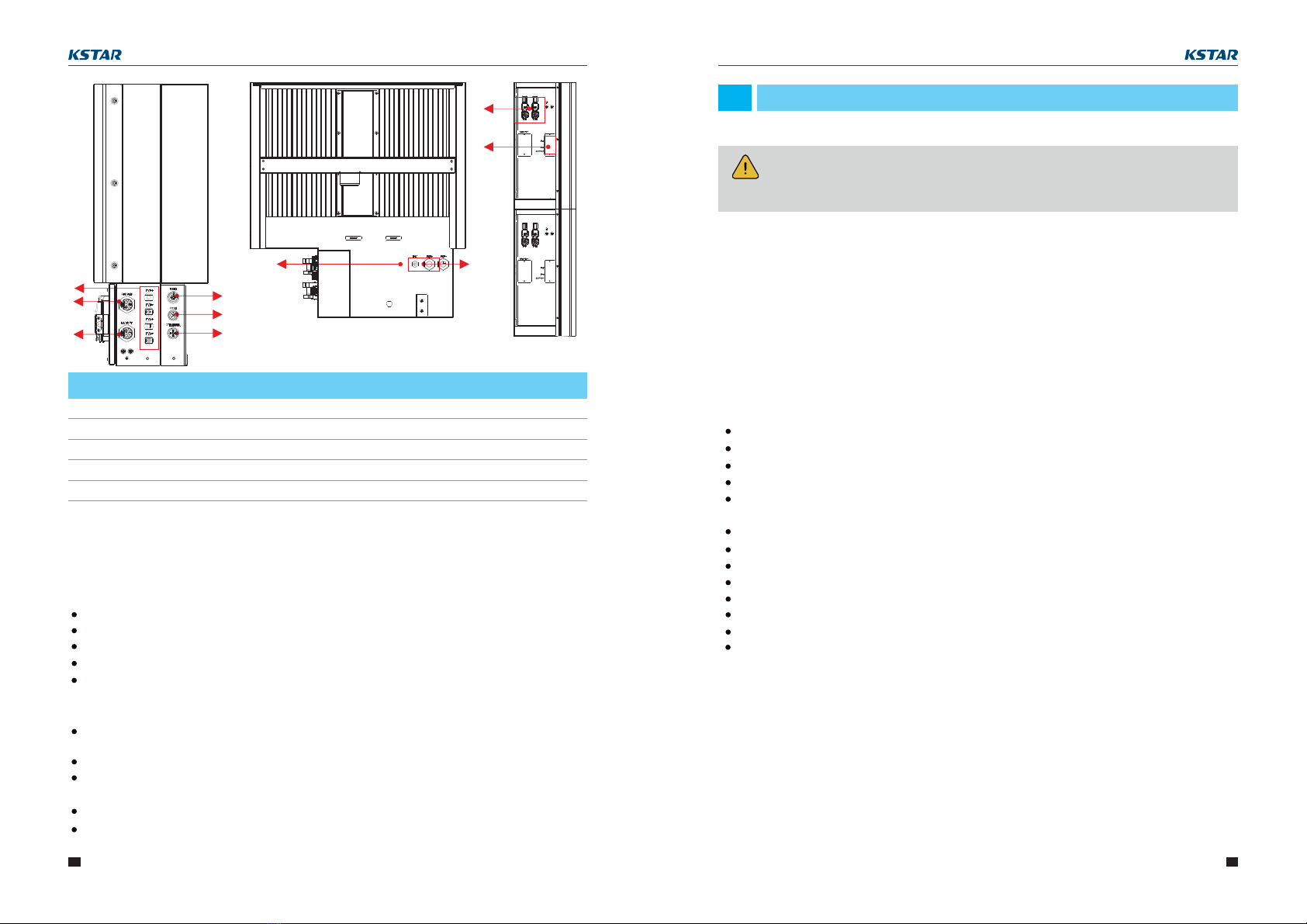
PV1, PV2
1GRID
2
BACKUP
3DRM4
COM
5CT/METER
6
INV
7BAT+,BAT-
8
DVC C DVC C
DVC C DVC A
DVC A DVC A
DVC C DVC C
Description Description
Object Object
DVC class DVC class
Figure 7 Cable Box Part without Covers
2
3
1
78
4
5
6
8
9
RJ45
9DVC C
14