KStar E8KT Instruction manual

202302 Ver:1.0
INSTALLATION, OPERATION &
MAINTENANCE MANUAL
E8KT/E10KT/E12KT
ENERGY STORAGE SYSTEM
Shenzhen Kstar New Energy Company Limited
Add:Kstar Industrial Park, Guangming Hi-Tech Park,
shenzhen ,P.R.CHINA
Tel:0755-21389008 Fax:0755-21389008
Web:www.kstar.com

Please keep the manual properly and operate in strict accordance with all safety
and operating instructions in this manual. Please do not operate the system
before reading through the manual.
Contact the nearest hazardous waste disposal station when the products or
components are discarded.
Copyright Statement

08
67
68
67
8.1 Alarm Code
8.2 Error Code
0969
Fault Diagnosis and Solutions
12 79
Quality Assurance
10 72
Product Specifications
11 77
Routine Maintenance
03
02
01
04
Installation
01
04
06
07
08
14
17
18
20
31
37
38
39
01
18
37
41
43
41
System Operation
1.1 System Introduction
1.3 Safety Introduction
1.4 Battery Safety Datasheet
1.5 General Precautions
1.6 Parts List
1.7 System Appearance
1.8 Liability Limitation
2.1 Installation Site and Environment
2.2 Installation
2.3 External CT Connection
3.1 Switch on
3.2 Switch off
3.3 Emergency Procedure
EMS Introduction and Set up
4.2 Display and Setting
CONTENTS
4.3 Configuration Menus Overview 48
Introduction
32
33
03
1.2 Operation Modes
07
64
64
64
SOLARMAN Smart APP
7.1 Registration
7.2 Create a Plant
06
60
60
Stick Logger Quick Guide
6.1 Download APP
6.2 Stick Logger Installation 60
60
60
6.3 Logger Status
6.4 Abnormal State Processing
63
6.5 Usage Methods and Notices for Reset Button
64
65
7.3 Add a Logger
7.4 Network Configuration
05
59
59
Battery Storage And Recharging
5.1 Battery Storage Requirements
5.2 Storage Expirations 59
59
5.3 Inspection Before Battery Recharging
Alarm Code and Error Code
4.1 Function Description
2.8 Single Line Diagram
2.4 DRED Port Connections (optional,only for DRM function)
2.5 COMM Port Connections
2.6 METER+DRY Port Connections 33
35
2.7 enerator connectionsG34

Figure1 DC-coupled Storage System – Scheme
Figure 3 Hybrid-coupled Storage System–Scheme
Introduction
01
E8KT/E10KT/E12KT can be applied in DC- coupled systems (mostly new installation), AC-
coupled systems (mostly retrofit) and Hybrid-coupled systems (mostly retrofit, and PV
capacity-increase), as the following schemes show:
User Manual User Manual
01 02
Figure 2 AC-coupled Storage System–Scheme
1.1 System Introduction PV
PV
Monitoring
Device
LAN
PV Inverter Grid Meter Grid
Backup Loads
Normal Loads
CT
GridGrid Meter
Backup Loads
LAN
Monitoring
Device
PV
Normal Loads
CT
GridGrid Meter
Backup Loads
LAN
PV Inverter
PV
Monitoring
Device
Normal Loads
CT

1.2 Operation Modes:
There are three basic modes that end users can choose via inverter screen/APP.
03 04
• BAT PRIORITY: Under this mode, the battery is only used as a backup power supply when
the grid fails and as long as the grid works, the batteries won’t be used to power the loads.
The battery will get charged with the power generated by the PV system or from the grid.
• PEAK SHIFT: This mode is designed for time-use mode customer. The customer is able to
set up the charging/discharging time & power via inverter screen or APP.
• SELF CONSUME: The energy generated by the solar panels will be used in the following
order: Feed the home loads; Charge the battery and then, feed into the grid.When the sun is
off, the load will be supported by battery to enhance self consumption. If the power supply
from the batteries is not sufficient, the grid will support the load demand.
$
TIME
Electricity Price
1.3.2 Operator Requirements
The operators should get a professional qualification, or be trained.
The operators should be familiar with the whole storage system, including compositions and
working principles of the system.
The operators should be familiar with the Product Instruction.
While maintaining, the maintainer is not allowed to operate any equipment until all the
equipment has been turned off and fully discharged.
The warning signs contain important information for the system to operate safely, and it is
strictly prohibited to tear or damage them. Ensure that the warning signs are always well-
functioned and correctly placed. The signs must be replaced immediately when damaged.
1.3.3 Protection of Warning Sign
1.3.1 Manual Keeping
This manual contains important information about operating the system. Before operating,
please read it very carefully.
The system should be operated in strict accordance with the instructions in the
manual,otherwise it can cause damages or loss to equipment, personnel and property.
This manual should be kept carefully for maintenance.
1.3 Safety Introduction
User Manual User Manual

1.4.1 Hazard Information
1.3.4.Setting of Warning Sign for Safety
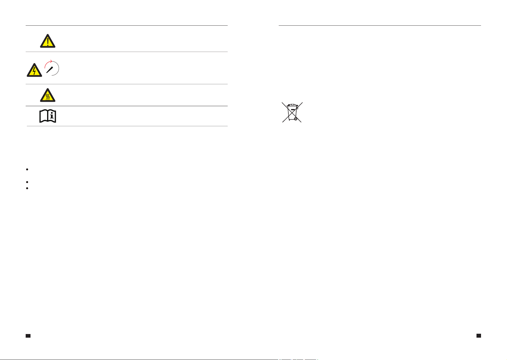
This sign indicates a hazardous situation which, if not avoided,
could result in death or serious injury!
This sign shows danger of hot surface!
Refer to the operating instructions.
The E8KT/E10KT/E12KT must not be touched or put into service until
5 minutes after it has been switched off or disconnected to prevent an
electric shock or injury.
During instruction, maintenance and repair, follow the instructions below to prevent
non-specialist personnel from causing misuse or accident:
Obvious signs should be placed at front switch and rear switch to prevent accidents caused
by false switching.
Warning signs should be set near operating areas.
The system must be reinstalled after maintenance or operation.
To ensure the electrical parameters to match requirements, related measuring equipment are
required when the system is being connected or tested.
Ensure that the connection and use matched specification to prevent electric arcs or shocks.
It is very likely that moisture may cause damages to the system. Repair or maintaining
activities in wet weather should be avoided or limited.
The battery system is part of the energy storage system which stores life-threatening high
voltage even when the DC side is switched off. Touching the battery outlets is strictly
prohibited. The inverter can keep a life-threatening voltage even after disconnecting it from the
DC and / or AC side. Therefore, for safety reasons, it must be tested with a properly calibrated
voltage tester before an installer works on the equipment.
Exempt from classification according to Australian WHS regulations.
Classification of the hazardous chemical
Other hazards
This product is a Lithium Iron Phosphate Battery with certified compliance under the UN
Recommendations on Transport of Dangerous Goods, Manual of Tests and Criteria, Part III,
subsection 38.3. For the battery cell, chemical materials are stored in a hermetically sealed
metal case, designed to withstand temperatures and pressures encountered during normal
use. As a result, during normal use, there is no physical danger of ignition or explosion and
chemical danger of hazardous materials' leakage. However, if the product is exposed to a fire,
added mechanical shocks, decomposed, added electric stress by misuse, the gas release
vent will be operated. The battery cell case will be breached at the extreme. Hazardous
materials may be released. Moreover, if heated strongly by the surrounding fire, acrid or
harmful fume may be emitted.
5min
1.3.5 Measuring Equipment
1.3.6 Moisture Protection
1.3.7 Operation After Power Failure
05 06
1.4 Battery Safety Datasheet
1.4.2 Safety Datasheet
For detailed information please refer to the provided battery safety datasheet.
User Manual User Manual
1.3.8. Information on environmental conservation and recycling
This Symbol indicates that the marked device must not be disposed of as normal
household waste. It must be disposed of at a collection center for the recycling of
electric and electronic equipment.

CAUTION:
Risk of injury through lifting or dropping the system. The inverter and battery are
heavy. There is risk of injury if the inverter or battery is lifted incorrectly or dropped
during transport or when attaching to or removing from the wall.
Lifting and transporting the inverter and battery must be carried out by more
than 2 people.
WARNING
Do not install the system in any environment of temperature below -25°C or over
60°C and in which humidity is over 95%.
Do not touch the system with wet hands.
Do not put any heavy objects on top of the system.
Do not damage the system with sharp objects.
Do not install or operate the system in potentially explosive atmospheres or
areas of high humidity.
Do not mount the inverter and the battery pack in areas containing highly
flammable materials or gases.
If moisture has penetrated the system (e.g. due to a damaged enclosure), do not
install or operate the system.
Do not move the system when it is already connected with battery modules.
Secure the system to prevent tipping with restraining straps in your vehicle.
A certified ABC fire extinguisher with minimum capacity of 2kg must be carried
along when transporting.
It is totally prohibited to smoke in the vehicle as well as close to the vehicle when
loading and unloading.
For the exchange of a battery module, please request for new hazardous goods
packaging if needed, pack it and let it be picked up by the suppliers.
In case of contact with electrolyte, rinse the affected areas immediately with
water and consult a doctor without delay.
Inverter
Risk of chemical burns from electrolyte or toxic gases. During standard operation, no
electrolyte shall leak from the battery pack and no toxic gases shall form. Despite careful
construction, if the Battery Pack is damaged or a fault occurs, it is possible that electrolyte
may be leaked or toxic gases formed.
Check the following parts list to ensure it is complete.
Delivers a total system separately on site to client, this consists of:
07 08
The transportation of E8KT/E10KT/E12KT must be made by the manufacturer or
an instructed . These instructions shall be recorded and repeated. personnel
DANGER
Do not touch uninsulated cable ends.
Do not touch the DC conductors.
Do not open the inverter and battery.
Do not wipe the system with damp cloth.
Have the system installed and commissioned by qualified with the personnel
appropriate skills only.
Prior to performing any work on the inverter or the battery pack, disconnect the
inverter from all voltage sources as described in this document.
Danger to life due to high voltages of the PV array, battery and electric shock. When exposed
to sunlight, the PV array generates dangerous DC voltage which will be present in the DC
conductors and the live components of the inverter. Touching the DC conductors or the live
components can lead to lethal electric shocks. If you disconnect the DC connectors from the
system under load, an electric arc may occur leading to electric shock and burns.
1.5 General Precautions
1.6 Parts List
User Manual User Manual
6×M5*12
4×MC4 1×User Manual
1×Collector
2×CT Connector 3×CT and
com cable 2×AC Collector
1 Mounting Panel×
5×ST6.3*50 5×D10*50
1×COM
Connector
5×M6 Gasket

09 10
PACK5.1
Accessory - Cable (PACK10.2)
Accessory - Cable (PACK20.4)
User Manual User Manual
4×M6 Gasket2×M5*12
1 Mounting Panel×
4×ST6.3*50 4×D10*50
DR-850
DB-850
DR-260
DB-260
G-1000
C-600
G-1000
C-600
DB-260
DB-1600DR-2600
DR-1100
DR-490
DB-490
G-2000
DR-490
DB-490
300~400mm

11 12
Accessory - Cable (PACK30.6) Accessory - Cable (PACK40.8)
User Manual User Manual
C-600
G-1000
DB-260
DR-2600 DB-2600 DR-1600
DR-2600 DB-2600 DR-2600
DB-850
DR-490
DB-490
G-2000
DB-490
DR-490
G-2000
C-2600
C-2600
300~400mm 300~400mm
C-600
G-1000
DB-260
DB-850
DR-3500 DB-2600 DR-2600 DR-2600 DB-2600 DR-3500
G-2000
C-2600
G-2000
C-2600
DR-490
DB-490
DR-490
DB-490
DB-490
DR-490
DB-490
DR-490
300~400mm 300~400mm

User Manual User Manual
Accessory - Mechanical Top cover
Accessory - Floor stand support
1
2
3
4
5
Hybrid Inverter
EMS Display Screen
Cable Box (connected to Inverter)
PACK5.1 (Battery 1)
PACK5.1 (Battery 2, if configured)
Object
Figure 4 E8KT/E10KT/E12KT Delivery Scope
1
2
3
5
4
Description
1.7 System Appearance
13 14

1.7.1 Cable Box Part
Figure 5 Inverter without Cable Box Covers– Front View
Figure 6 Cable Box Part without Covers – Front View
15 16
1
2
3
Battery circuit breaker
DC isolation switch
Output terminal block(BACK UP)
Object Description
User Manual User Manual
3
2
1
PV1, PV2
1
ON GRID
2BACKUP
3DRM OR PARALLEL24
COM
5METER+DRY
6
BAT
7BAT+,BAT-
8
DVC C DVC C
DVC C DVC A
DVC A DVC A
DVC A DVC A
Description Description
Object Object
DVC class DVC class
Figure 7 Cable Box Part without Covers
3
21
5
8
9
COMM
9DVC A
6
7
4
10
10 CT DVC A
11
PARALLEL111 DVC A
Note: The DVC indicates the minimum required level of protection for the circuit.
Decisive voltage
Classification
(DVC) a.c. voltage
r.m.s.
U ACL
a.c. voltage
peak
U ACPL
d.c. voltage
mean
U DCL
Limits of working voltage
V
A*
B
C
≤25
(16)
50
(33)
>50
(>33)
≤35.4
(22.6)
71
(46.7)
>71
(>46.7)
≤60
(35)
120
(70)
>120
(>70)
The table values in parentheses are to be used for PCE or portions of PCEs rated
for installation in wet locations as addressed in 6.1 for environmental categories
and minimum environmental conditions.
*DVC-A circuits are allowed under fault conditions to have voltages up to the DVC-
B limits, for maximum 0.2 s.

Installation
Any product damage or property loss caused by the following conditions, Company does
not assume any direct or indirect liability.
2.1.1 General
NOTE:
Please be cautious unpacking the battery, otherwise components could be damaged.
This Manual introduces the basic steps to install and set up E8KT/E10KT/E12KT.
This E8KT/E10KT/E12KT energy storage system is outdoor version and can be installed in an
outdoor location.
When E8KT/E10KT/E12KT systems are installed in a room, E8KT/E10KT/E12KT must not be
hampered by the structure of the building, the furnishings and equipment of the room.
The E8KT/E10KT/E12KT is naturally ventilated. The location should therefore be clean, dry
and adequately ventilated. The mounting location must allow free access to the unit for
installation and maintenance purposes, and the system panels must not be blocked.
The following locations are not allowed for installation:
The E8KT/E10KT/E12KT shall not be installed :
1.In restricted locations as defined for panels in AS / NZS 3000;
2.Within 600mm of any heat source, such as hot water unit, gas heater, air conditioning
unit or any other appliance.
3.Within 600mm of any exit;
4.Within 600mm of any window or ventilation opening;
5.Within 600mm of side of other device.
2.1.2 Restricted Locations
Habitable rooms;
Ceiling cavities or wall cavities;
On roofs that are not specifically considered suitable;
Access / exit areas or under stairs / access walkways;
Where the freezing point can be reached, such as garages, carports or other places as
well as wet rooms (environmental category 2);
Locations with humidity and condensation over 95%;
Places where salty and humid air can penetrate;
Seismic areas - additional security measures are required;
Sites with altitude over 2000m;
Places with an explosive atmosphere;
Locations with direct sunlight or a large change in the ambient temperature;
Places with flammable materials or gases or an explosive atmosphere.
Product modified, design changed or parts replaced without authorization;Company
Changes, repair attempts and erasing of series number or seals by Non-Company
technician;
System design and installation are not in compliance with standards and regulations;
Fail to comply with the local safety regulations (VDE for DE, SAA for AU);
Transport damage (including painting scratch caused by rubbing inside packaging
during shipping). A claim should be made directly to shipping or insurance company
in this case as soon as the container/packaging is unloaded and such damage is
identified;
Fail to follow any/all of the user manual, the installation guide and the maintenance
regulations;
Improper use or misuse of the device;
Insufficient ventilation of the device;
The maintenance procedures relating to the product have not been followed to an
acceptable standard;
Force majeure (violent or stormy weather, lightning, overvoltage, fire etc.);
Damages caused by any external factors.
02
17 18
1.8 Liability Limitation
2.1 Installation Site and Environment
User Manual User Manual

2.1.3 Barrier to Habitable Rooms
A E8KT/E10KT/E12KT installed in any corridor, hallway, lobby or the like and leading to an
emergency exit shall ensure sufficient clearance for safe egress of at least 1 meter.
The E8KT/E10KT/E12KT must also not be installed in potentially explosive atmospheres for
gas cylinders that are heavier than air gases and have a vent clamp in accordance with AS /
NZS 3000.
To protect against the spread of fire in living spaces where the E8KT/E10KT/E12KT is
mounted or on surfaces of a wall or structure in living spaces with a E8KT/E10KT/E12KT on
the other side, the wall or structure shall have a suitable non-combustible barrier. If the
mounting surface itself is not made of a suitable non-combustible material, a non-combustible
barrier can be placed between the E8KT/E10KT/E12KT and the surface of a wall or structure.
If the E8KT/E10KT/E12KT is mounted at a wall or at a distance of 300mm from the wall or the
structure separating it from the habitable space, the distances to other structures or objects
must be increased. The following distances must remain free:
(i) 600 mm beside the E8KT/E10KT/E12KT;
(ii) 500 mm above the E8KT/E10KT/E12KT;
(iii) 600 mm before the E8KT/E10KT/E12KT.
If the distance between the E8KT/E10KT/E12KT and the ceiling or any object above the
system is less than 500mm, the ceiling or structural surface above the system must be
made of noncombustible material within a radius of 600mm around the system.
The E8KT/E10KT/E12KT must be mounted to ensure the highest point is not more than
2.2m above the ground or the platform.
Step 1 Remove the battery and inverter from the packaging box.
19 20
Figure 8 Limited Distance of Installation to Neighboring Objects
Step 2 Assemble the battery mounting panel on the battery.
Figure 10 Assemble Battery Mounting Panel
M5*12 Screws
2.2.1 Battery Installation
2.2 Installation
Step 3 Position the battery parallell to the wall and use a Φ10mm drill to drill holes at a
depth of about 70mm in the wall for subsequent fixation of the mounting plates.
Debris Baffle, drill φ10,
depth about 70 mm
Figure 11 Battery Installation -
Drill Holes
≥600mm≥600mm
≥500mm
≥600mm
Top----------- 500mm
Front--------- 600mm
Laterals------600mm
User Manual User Manual
Note: A shelter must be installed above the SINERGY

Hang the inverter onto the mounting panels, adjust the entire system andensure
that the battery and the inverter have been securely hung onto the panels andbrackets.
Step 4
Remove the debris baffle and secure the battery to the wall with screws and gaskets.
NOTE:
The type B RCD must be installed on the backup port of the system according to
local regulations .
Figure 12 Battery Installation – Mounting on the Wall
21 22
ST6.3*50
Gasket
To assemble the second (and all other) battery, repeat steps 6 and 7,respectively.
Figure 13 Battery Installation
Second Battery Installation
2.2.2 Inverter Installation
Step 7
Inverter Installation.
Figure 14 Inverter Installation
Figure 15 Inverter Installation on the Wall
Step 6
Step 5
User Manual User Manual
M5-12

Please make AC cables on site.
Please follow the AC cable requirements below.
23 24
Step 8-1
Step 8
For backup connection, 12AWG or 4mm² cable is required to be used. For grid connection,
10AWG or 6mm² cable is required to be used. Please make sure the resistance of cable is
lower than 1 ohm.
b. Insert the conductor into the suitable ferrule acc. to DIN 46228-4 and crimp the contact.
c. Unscrew the swivel nut from the threaded sleeve and thread the swivel nut and threaded
sleeve over the AC cable.
d. Insert the crimped conductors L, N and PE into the corresponding terminals and tighten the
screw with a hex key wrench screw driver (size:2.5, 1.2~2.0 N.m). Ensure that all conductors
are securely in place in the screw terminals on the bush insert.
e. Screw the swivel nut onto the threaded sleeve. This seals the AC connector and provides
strain relief for the AC cable. When doing so, hold the bush insert firmly by the locking cap.
This ensures that the swivel nut can be screwed firmly onto the threaded sleeve.
f. Assembly the plug shell ,adapter as below picture, Push the adapter and Shell by hand until
a “Click” is heard or felt.
g. Plug the AC connector into the jack for the AC connection by hand until a “Click” is heard
or felt.
User Manual User Manual
A
B
L1
L2
L3
N
PE
WARNING:
There are"1,2,3,N, '' symbols marked inside the connector, the Line wire of
grid must be connected to "1,2,3" terminal; the Neutral wire of grid must be
connected to "N" terminal; the Earth of grid must be connected to " "
10mm
6mm²
A
B
External diameter
Copper conductor cross-section
Object Description Value
Step 1.Strip the protection layer and insulation layer by specific length,as described in the
figure below.
Locking screw
Pin
1
2
Description
R
S
T
N
PE
3
N
≤50mm
L=E+(2~3)mm
E
R
S
T
N
PE
R
S
T
N
PE
Step 2. Make the cable and crimp theterminal.
When locking the power grid cable into the external power grid connector, the RST should be
marked on the corresponding cable, because when installing the CT, the three CTs with RST
identification need to be buckled on the RST line of the corresponding identification.

25 26
Step 8-2 Connect the Backup and Grid cables in advance according to the connector
mode, and connect them to the Backup and Grid board connectors in turn.
(8) Use tool to clamp the AC wiring terminal and wire rod; screw the nut, but do not
tighten it. Make sure that the cable is free to pass through the waterproof components.
Once the terminal is connected to the right site of the inverter, tighten the nut.
(9) Connect the AC wiring terminal to the corresponding hole site of the inverter and
lock it with a screw driver or electric screw driver (suggestion: stem diameters and
torsion of screwdriver or electric screwdriver should be 4mm and 8~12kg-f.cm
respectively)
(10) Tighten the nut.
(11) Circuit breaker parameters are recommended:
Back-up 25A/400Vac 6KA
On-grid32A/400Vac 6KA
Figure 16
Figure 17 Cable Box Bottom View, Wiring Connectors
User Manual User Manual

Connect the BAT communication cable of the cable box from Step 13 to the
topmost battery at the right side. Then use the communication cable supplied with the
batteries to connect the batteries to each other via the respective connectors on the left side.
After you have connected all the modules together, close all covers (if you want to connect
further battery modules, you must mount them before closing).
Step 9
27 28
Figure 19 Wiring the Communication Cable
Connect the power cables of the bottom battery from Step 4 to the sideterminals of
the top battery. Make sure that red connects to red and black connects toblack.
Step10
Figure 20 Wiring the Battery Power Cable
User Manual User Manual

29 30
NOTE:
Recommended AC circuit breaker rating is 32A for grid, 25A for backup.
STATEMENT:
The method of anti-islanding protection is power variation
NOTE:
It is necessary to disconnect the power line, communication line and communication
line between battery pack and inverter to manually sleep all battery packs.
Close the lid and tighten the screw.
Step12
Figure 22
Close the battery covers and connect the PV-MC4 connectors to the system
(connection on both sides). Also, connect all AC cables, the meter communications cable
METER, and the Ethernet cable LAN. Then close the cable box cover.
The installation is now complete.
Step11
Figure 21 PV Wiring
User Manual User Manual
4*MC4
Captive Screws
Step13 Commissioning of the energy storage system
After the installation of the energy storage system completed, in order to ensure the normal
operation of the system, it is necessary to check the battery, PV and grid input parameters
according to the following steps.
a. Manually press the reset button of the battery pack touch screen for 3-5S, then turn on the
battery switch of both the battery pack and the hybrid inverter after the green light of the
capacity indicator on the battery pack touch screen is on and there is no red light alarm
indication, and check the screen Battery and Battery parameter interfaces after the
inverter LCD screen is on for 5-10S, and check whether the temperature, voltage and capacity
are normal (the temperature determination is roughly based on the current ambient
temperature of the system, the voltage determination is in the range of 50V ± 3V, and the
capacity determination is 100AH for a single battery pack, when multiple battery packs are
connected in parallel, the capacity is the number of battery packs multiplied by 100AH).
b. After PV input connected and PV switch of the hybrid inverter closed, check whether the
voltage display on the PV input display interface is normal.
c. After connecting to the grid, check whether the voltage display on the Grid-connected
output interface is normal.

31 32
The electricity meter should be mounted and connected at the grid transition point (feed-in
point) so that it can measure the grid reference and feed-in power.
1. Loosen the nut, and untangle the single-aperture sealing ring.
2. Install the waterproof component and screw on the waterproof sheath nut.
3. Open the external CT wiring port, the arrow points to the direction of the power grid, put the
wire into the external CT card slot, and buckle the buckle.
External CT should be placed near the power grid.
DRED means demand response enable device. The AS/NZS 4777.2:2015 required inverter
need to support demand response mode(DRM). This function is for inverterthat comply with
AS/NZS 4777.2:2015 standard. Inverter is fully comply with all DRM. A 8P terminal is used for
DRM connection.
Pin Pin
1
4
3
2
Description Description
R phase CT positive electrode(White)
S phase CT positive electrode(White)
If CT test pass but inverter still can't achieve export power (power is not controllable
or always 0 power output).Please check installation location of the CT.
line L
User Manual User Manual
Figure 24
6
5T phase CT positive electrode(White)
R phase CT negative pole(Black)
S phase CT negative pole(Black)
T phase CT negative pole(Black)
PIN
1
6
2
7
3
5
PIN Name Description
Figure 25 DRM connector
8
4
G
V
DRM4/8
V
DRM3/7
DRM2/6
DRM1/5
DRM0
GND
5VDC Voltage Supply
Relay contact 4 input
5VDC Voltage Supply
Relay contact 3 input
Relay contact 2 input
Relay contact 1 input
Relay contact 0 input
Connected to RRCR
Not connected
Relays common node
K4-Relay 4 output
Relays common node
K3-Relay 3 output
K2-Relay 2 output
K1-Relay 1 output
K0-Relay 0 output
The inverter is preconfigured to the following RRCR power levels.
DRM0
1
1
1
1
1
0
DRM1/5
0
1
1
1
1
X
DRM2/6
1
0
1
1
1
X
DRM3/7
1
1
0
1
1
X
DRM4/8
1
1
1
0
1
X
Active Power
0%
30%
60%
100%
100%
Standby
Cos(Q)
1
1
1
1
1
1
RRCR

Pin Pin
1
5
2
4
Description Description
6
3
DRY contact
DRY contact
GND
Input signal
RS485-B
RS485-A
PIN6
PIN5
Note:The CT arrow points to GRID.
When using the generator, user can refer to the following connection methods.
Pin Pin
1
4
2
3
Description Description
GND
+5V RS485-A
RS485-B
Note:
1.The Smart Meter(ADW300W or SDM630MCT are suggested.) with CT is already configured;
please do not change any settings on the Smart Meter.
2.One Smart Meter can be used with only one inverter.
3.three CTs must be used for one Smart Meter and must be connected on the same phase
with the Smart Meter power cable.
Smart Meter & CT connection diagram
METER+DRY port
6
5
2
3
33 34
User Manual User Manual
2.7 Generator connections
This manual suits for next models
2
Table of contents
Other KStar Storage manuals
Popular Storage manuals by other brands

Emulex
Emulex SD590 Installation and maintenance manual

HP
HP StorageWorks P4000 Series user guide

Buffalo
Buffalo MiniStation HD-PF320U2 Specifications

Supermicro
Supermicro Supero SC847DE16-R1K28LPB user manual

Rocstor
Rocstor ROCSERVE 4RTe Installation and configuration manual

Packard Bell
Packard Bell EXPRESS 5800 user guide