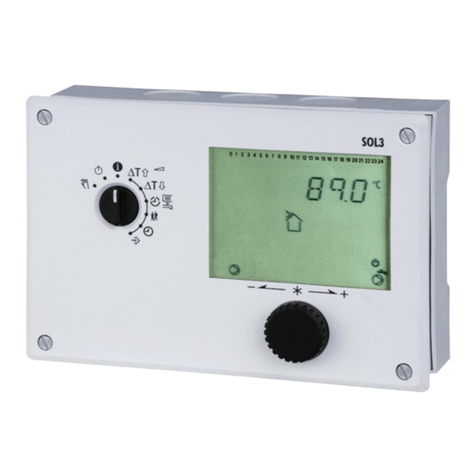
KT-Elektronik ZPR-D User manual

Solar thermal controller
ZPR-D
Quick installation and
operating manual
Firmware version 1.0x,
Mai 2011

Quick installation and operating manual KT-Elektronik
Warranty
We permanently enhance our products, therefore we reserve the right to make changes to our products at any
time and without prior notice.
We take no responsibility for the accuracy or completeness of this manual. o liability can be accepted for the
use of our products for a buyer specific purpose. Buyer claims, especially claims for damages including lost
profits or other financial losses are excluded. This does not apply if the damage caused by intent or gross
negligence. In case of negligent violations of major contractual obligations, our liability is limited to the
foreseeable damage
Security advices
Only qualified personnel that is familiar with installation and commissioning of this product
is allowed to mount and put into operation the device. Appropriate shipping and storage
are assumed.
The product is designated for use in heavy current equipment. Installation and
maintenance have to be performed according to the corresponding safety regulations.
Content
Commissioning..........................................................................................................................................3
Mounting.............................................................................................................................................3
Electrical connection ..........................................................................................................................3
Operating.................................................................................................................................................. 4
Display ..................................................................................................................................................... 4
System variants.........................................................................................................................................5
System variant 1: Solar thermal system.............................................................................................5
System variant 2: Storage tank heat exchanger................................................................................6
System variant 3: Raise return flow....................................................................................................6
System variant 4: Charging pump control I........................................................................................6
Technical specifications............................................................................................................................ 7
Application
The digital solar thermal controller ZPR-D is a universally applicable and robust device for the temperature difference control
for the area of the solar thermal systems, heating systems and air conditioning systems.
The device distinguishes itself by special economic efficiency and is held consciously extremely easy in service and
assembly. The technical implementation of the solar thermal controller ZPR-D considers in special way the demands of the
building automation.
These short instructions should deliver with assembly and introduction of the device necessary information.
Further information is retrievable under http://www.kt-elektronik.de.
2KA_11986_ZPR-D_E 002

KT-Elektronik ZPR-D
Function
The digital solar thermal controller ZPR-D has two rotary switches serveable on the front. With the rotary switches are given
the threshold ∆TS and according to operating purpose a Maximum or Set/pont of temperature (TMax, TS).
The device continuously mieasures two connected temperature sensors and determines the temperature difference ∆TI. The
relay output is switched as a result from the comparison of the temperature difference ∆TI and the opposed temperature
difference ∆TS .
At the relay output pumps, valves, flaps or engines can be connected.
In different operating modes storage tank maximum temperature limitation, system overtemperature protection and pump
blocking protection is realized as well as minimum running time and minimum idle time is considered.
A two-digit announcement serves the representation of the sensor temperatures and status information.
Commissioning
Mounting
The digital solar thermal controller
ZPR-D is to snap into the DI rail
TS32 or TS35 (according to
E 50022) using the universal base.
Electrical connection
The digital solar thermal controller ZPR-D ist to connect
according to the right shown connection schema.
Overvoltage protection measures:
•If signal lines are routed outside by buildings or about
bigger distances, suitable overvoltage protection measures
hit!
•The shield of the signal lines which are routed outside by
buildings must be earthed stream-load-bearing and on both
sides.
•The overvoltage protector are to be installed in the entry of
the cabinet.
•Commisioning of a pump at the
potentialfree switching output:
connect terminal A2 to terminal L;
install pumpe at terminal A1 and
terminal
KA_11986_ZPR-D_E 002 3

Quick installation and operating manual KT-Elektronik
Operating
The two-digit 7-segment display serves the presentation of the temperature values of the
sensors as well as from status advises and error messages of the ZPR-D.
IIn the front of the ZPR-D two switch waves of the rotary switch are visible which can be
adjust with a slit screwdriver (size 4 mm) in the position which corresponds to the desired
scale value.
Rotary switch for Maximum temperature or temperature set point
Rotary switch for temperature threshold
In addition to the setting of the temperature threshold the manual operating mode is
connected with the rotary switch for the plumber. The relay output is switched on in the
rotary switch position ‚on' permanently, and is switched off in rotary switch position‚ off'
permanently.
Anzeige
With a green LED (right hand) the working condition of the ZPR-D is indicated. Mistake
states are shown with sparkling in different mark-space ratio.
The yellow LED (left hand) lights if the contact of the relay exit is closed.
Display
To the presentation of temperature values of the sensors as well as from status advises and error messages a two-digit
display is integrated into the front of the ZPR-D.
In the corners of right below and on the top left is a point which gives the accordant sensor at the display of a temperature.
Sensor 1 becomes marked by the point on the top left, sensor 2 by the point of right below.
Mistakes show in the left place to the letters 'E', advises or status informations a 'H'.
Examples:
Collector temperature is measured: 75 °C
Storage tank temperature is measured: 43 °C
Sensor 2 damaged
Collector minimum temperature falls below
4KA_11986_ZPR-D_E 002

KT-Elektronik ZPR-D
System variants
System variant 1: Solar thermal system
The program controls the solar circuit pump depending
on the temperature of the solar collector and the
storage tank temperature. If the temperature in the
solar collector is higher than the buffer temperature,
the solar circuit pump is turned on. The solar pump
remains running for a minimum running time and is
earliest turned on after a minimum idle time.
The buffer is charged until the maximum storage tank
temperature is reached or the start-up criteria is not
met any more.
CF1 Sensor 1
SF1 Sensor 2
Overheating protection In solar thermal systems it comes to the overheating of the solar fluid if the energy from the
collectors can be led away not enough. In this stagnation case the medium can evaporate. In
this case typically used solar pumps cannot build up enough pressure to lift the liquid
medium up to the highest system point (collector escape). In this working condition the pump
is considerably loaded, no solar energy is won to the use and electric energy is used for the
pump.
In the stagnation case the solar pump CP1 is switched OFF at a collector temperature of
130 °C with a hysteresis by 20 K.
Actual pump
running/idle time
The solar pump CP1 is switched on by presentation of the thermal switch condition described
on top on at least 1 minute. The solar pump remains switched off for at least 3 minutes if the
thermal switch condition is not given any more.
Collector minimum
temperature
At low collector temperatures there sinks the efficiency of the solar thermal system, because
the energy consumption of the solar pump is unfavorably high in proportion to the solar
energy yield. The solar pump CP1 is only switched on if the collector temperature at least 20
°C amounts.
Collector Anti-freeze The collector pump is turned on if the temperature at the collector sensor drops below 5 °C.
At 6 °C it is turned off again, but only after the minimum running time set elapsed.
This customized function is not available in standard devices.
Status indication using Power-LED ● O ○ OFF Display
Device powered-on 2 seconds OFF ● ● ● ● ● ● ● ● ● ● ● ● ● ●
Function without additional information ● ● ● ● ● ● ● ● ● ● ● ● ● ● ● ● ● ● ● ● ● ●
Sensor break of Sensor1 (Error) ● ○ ○ ○ ○ ○ ○ ○ ○ ○ ○ ○ ○ ○ ○ ○ ○ ○ ○ ○ ○ ○ E1
Sensor break of Sensor2 (Error) ● ○ ● ○ ○ ○ ○ ○ ○ ○ ○ ○ ○ ○ ○ ○ ○ ○ ○ ○ ○ ○ E2
Pump minimum running/idle time ● ● ● ● ● ● ● ● ● ● ● ○ ○ ○ ○ ○ ○ ○ ○ ○ ○ ○
Collector Minimum temperature falls below ○ ● ● ● ● ● ● ● ● ● ● ● ● ● ● ● ● ● ● ● ● ● H1
Storage tank maximum temperature exceeded ○ ● ○ ● ● ● ● ● ● ● ● ● ● ● ● ● ● ● ● ● ● ● H2
Collector overheating protection temp. exceeded ○ ● ○ ● ○ ● ● ● ● ● ● ● ● ● ● ● ● ● ● ● ● ● H3
Collector frost protection temperature falls below ○ ● ○ ● ○ ● ○ ● ● ● ● ● ● ● ● ● ● ● ● ● ● ● H4
KA_11986_ZPR-D_E 002 5

Quick installation and operating manual KT-Elektronik
System variant 2: Storage tank heat exchanger
The storage tank charging pump LP1 runs if the storage tank
temperature SF1 is higher around the adjusted temperature
threshold (lower rotary switch) than the storage tank
temperature SF2 and the storage tank temperature SF2 is not
greater than the adjusted storage tank maximum temperature
(upper rotary switch).
SF1 Sensor 1
SF2 Sensor 2
System variant 3: Raise return flow
The switching valve UV (3-way valve) routes the heating circiut
return flow about the storage tank if the storage tank
temperature SF1 is higher around the adjusted temperature
threshold (lower rotary switch) than the heating circiut return
flow temperature RüF.
The upper rotary switch has no function in this system variant.
SF1 Sensor 1
RüF Sensor 2
System variant 4: Charging pump control I
The storage tank charging pump LP1 runs if the boiler
temperature KF1 is higher around the adjusted temperature
threshold (lower rotary switch) than the storage tank
temperature SF1 and the storage tank temperature SF1 is not
greater than the adjusted storage tank maximum temperature
(upper rotary switch).
KF1 Sensor 1
SF1 Sensor 2
6KA_11986_ZPR-D_E 002

KT-Elektronik ZPR-D
Technical specifications
Inputs 2 Inputs for temperature sensor Pt 1000
Outputs 1 isolated/potential-free relay outputs with varistor (snubber)
Ma power handling 250 V AC, 2A (at cos j = 1)
Operating voltage 85 to 250 V, 48 to 62 Hz, ma . 0.7 VA
Ambient temperature 0 to 40 °C (operating),
–10 °C to 60 °C (storage and shipping)
Type of protection IP 40 according to IEC 529
Protection class II according to VDE 0106
Pollution degree 2 according to VDE 0110
Overvoltage category II according to VDE 0110
Humidity class F according to VDE 40040
Noise immunity according to EN 61000-6-1
Noise emission according to EN 61000-6-3
Assembly DIN rail mounting
Housing B H T (mm) 27 96 60
Housing material PA6 (Base), PA66 (Housing), PC (Front)
Connection Terminals 0.08 – 1.5 mm² 250 V / 4 kV / 15 A (ma 0.5 Nm)
Weight appro 0.5 kg
KA_11986_ZPR-D_E 002 7

KT-Elektronik GmbH
Berlinickestrasse 11
12165 Berlin
Telefon: (030) 79 08 05-0
Telefa : (030) 79 08 05-20
e-mail: [email protected]
Internet: http://www.kt-elektronik.de KA_11986_ZPR-D_E 002
05/2011
Table of contents
Other KT-Elektronik Controllers manuals
Popular Controllers manuals by other brands

CD Automation
CD Automation REVO CL 1PH user manual

AUMA
AUMA SAEx 07.2 Operation instructions

Mitsubishi Electric
Mitsubishi Electric MELSERVO-J5 MR-J5-G Series user manual

ESPRIT
ESPRIT FALCON-80 user manual

National Instruments
National Instruments PXI-8150 Series installation guide

Texas Instruments
Texas Instruments LM2734 manual