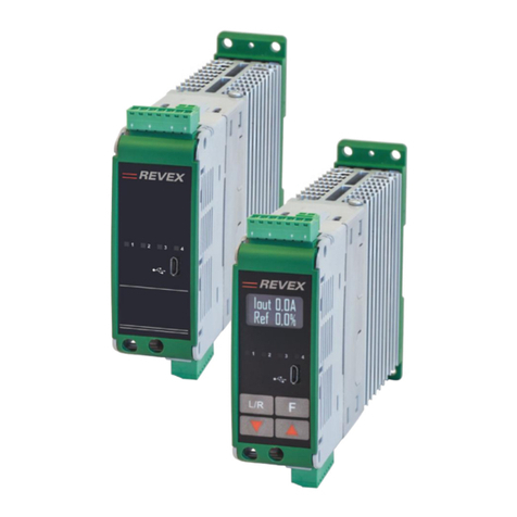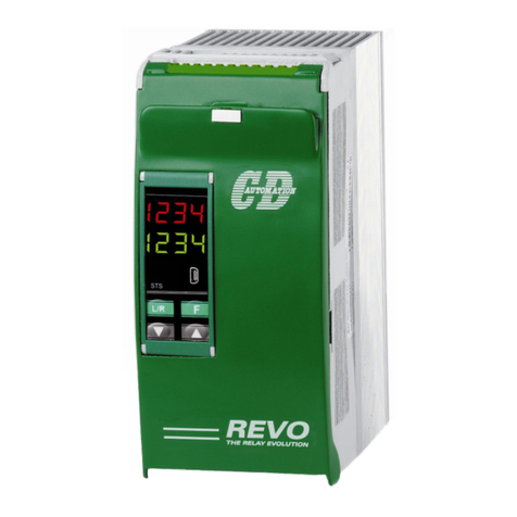
CD Automation srl REVO CL User’s Manual
3
1Important warnings for safety ....................................................................................... 6
2Note ............................................................................................................................... 7
3Introduction ................................................................................................................... 8
4Advantages compared with analog thyristor unit ........................................................... 8
5Software Configurator CDA Thyristor configurator software .......................................... 9
6Quick Start ................................................................................................................... 10
7Basic Configuration and sizing...................................................................................... 11
8Identification and Order Code ...................................................................................... 12
8.1 Identification of the unit 12
8.2 Order Code 13
9Technical Specifications ............................................................................................... 14
9.1 General features: 14
9.2 Input features: 14
9.3 Output features(power device): 14
10 Installation................................................................................................................... 15
10.1 Environmental installation conditions 15
10.2 Derating Curve 15
10.3 Dimensions and Weight 16
10.4 Fixing holes 16
11 Wiring instructions ....................................................................................................... 17
11.1 Access to L1 –T1 terminal Screw 18
11.2 Command Terminals 19
11.2.1 TERMINAL BLOCK M2..........................................................................................................................19
11.2.2 TERMINAL BLOCK M1..........................................................................................................................19
11.2.3 TERMINAL BLOCK M3..........................................................................................................................19
11.2.4 TERMINAL BLOCK M4..........................................................................................................................19
11.3 Schematic 20
11.4 Connection Diagram 21
12 Control Panel ................................................................................................................ 22
12.1 Scroll the parameters 23
12.2 Operator Menu 24
12.3 Setup Menu 27
12.4 Hardware Menu 30
12.5 Control Panel Led 33
12.6 Displayed Alarms 33
13 Input output signal....................................................................................................... 34
13.1 Digital Input 34
13.1.1 START/STOP (TERMINAL 3OF M2) .........................................................................................................34
13.1.2 CONFIGURABLE INPUT (TERMINAL 4OF M2) ..............................................................................................34
13.2 Digital Output (terminal 14-15-16 of M1) 34
13.3 Analog Input (Terminals 5 of M2 and 13 of M1) 34
13.3.1 PRIMARY INPUT.................................................................................................................................34
14 Heater Break alarm and SCR short circuit (HB Option) ................................................. 35
14.1 Heater break Calibration procedure 35
14.2 HB alarm contact 35
15 Firing type .................................................................................................................... 36
15.1 Phase Angle (PA ) 36
15.2 Soft Start with Phase Angle (S+PA ) 36
15.3 Delay Triggering with Burst Firing (DT+BF ) 37
16 Current Limit ................................................................................................................ 39
16.1.1 CURRENT LIMIT SETTING .....................................................................................................................39
16.1.2 CURRENT LIMIT TUNING PROCEDURE........................................................................................................39
17 Feed-back type ............................................................................................................. 40
18 Electronic boards.......................................................................................................... 41
