3 WORK 7
3.5 Recharging the battery
Warning
Risk of injury Battery acid and battery gases cause serious chemical burns.
–Keep batteries out of the reach of children.
–Wear suitable protective clothing and goggles.
–Avoid contact with battery acid and battery gases.
–Keep sparks and open flames away from the battery. Only charge in well-ventilated rooms.
–In the event of skin contact, rinse with large amounts of water. If battery acid gets in the eyes, rinse with water for at least
15 minutes and contact a physician.
Warning
Environmental hazard The battery contains elements that are harmful to the environment.
–Do not dispose of batteries with the household waste. Dispose of a defective battery in an environmentally friendly manner.
Give the battery to your authorized KTM dealer or dispose of it at a collection point for used batteries.
Warning
Environmental hazard Hazardous substances cause environmental damage.
–Oil, grease, filters, fuel, cleaners, brake fluid, etc., should be disposed of as stipulated in applicable regulations.
Info
Even when there is no load on the battery, it discharges steadily.
The charge state and the type of charge are very important for the service life of the battery.
Rapid recharging with a high charging current shortens the battery's service life.
If the charging current, charging voltage, and charging time are exceeded, electrolyte escapes through the safety valves. This
reduces the battery capacity.
If the battery is depleted from starting the vehicle repeatedly, the battery must be charged immediately.
If the battery is left in a discharged state for an extended period, it will become over-discharged and sulfate, destroying the
battery.
The battery is maintenance-free, i.e., the acid level does not have to be checked.
If the battery is not charged using the KTM battery charger, the battery must be removed for charging. Otherwise, overvoltage
may damage electronic components. Charge the battery according to the instructions on the battery housing.
Preparatory work
–Switch off all power consumers and switch off the engine.
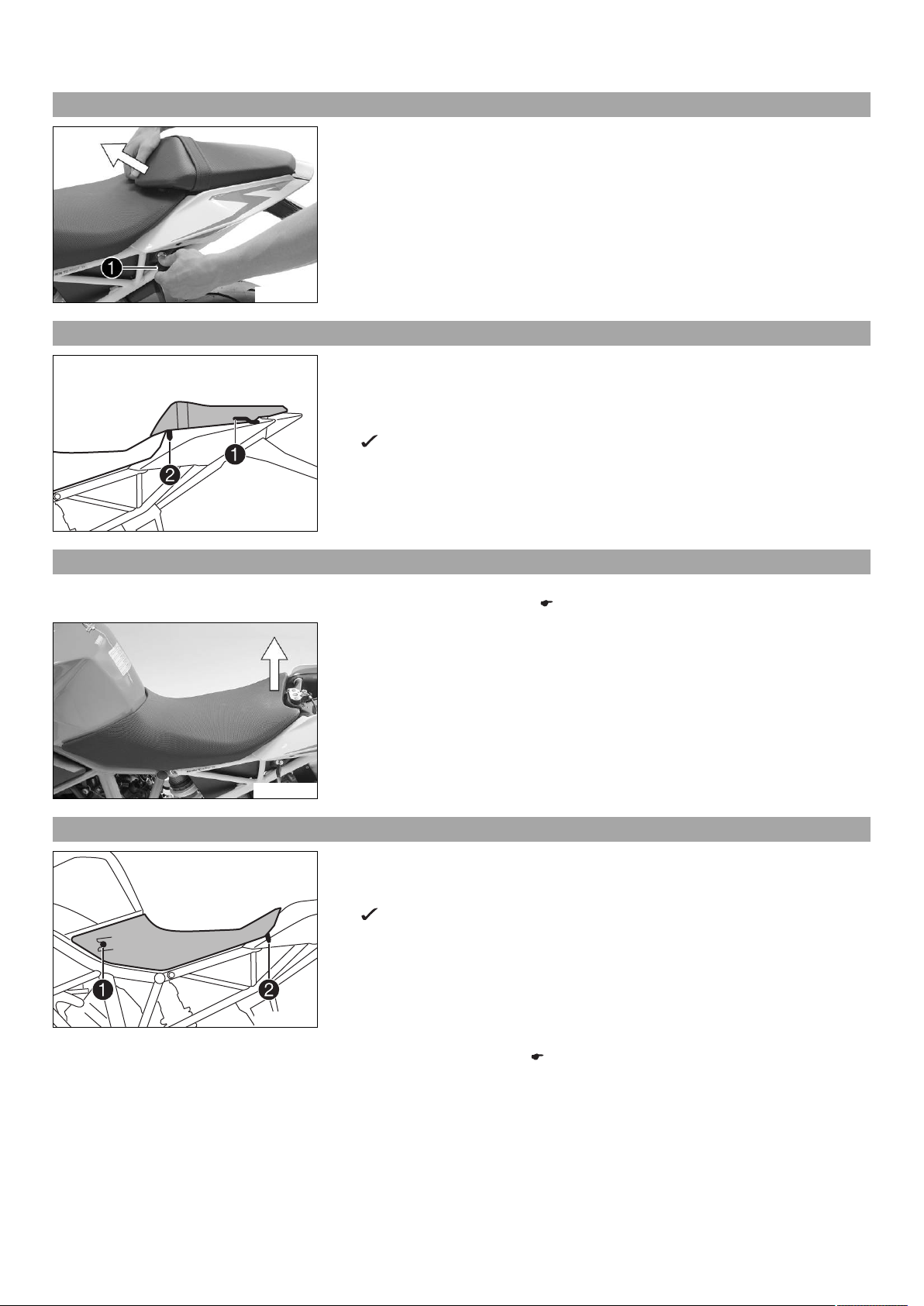
–Remove the passenger seat. ( p. 6)
–Remove the front rider's seat. ( p. 6)
L01482-10
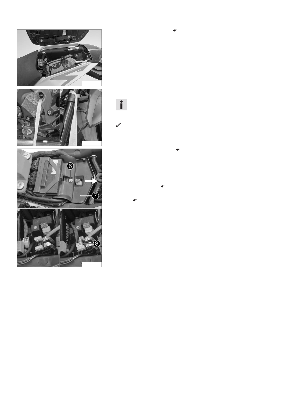
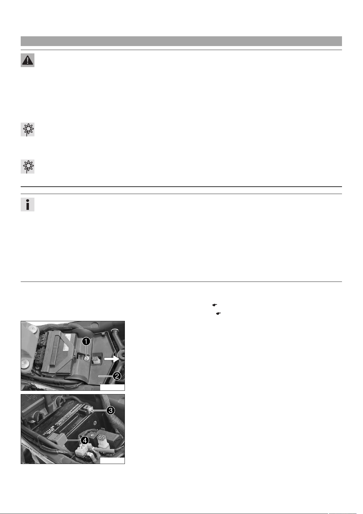
Main work
–Remove screw .
–Lift cover at the rear and pull toward the rear.
–Fold up the cover.
L01483-12
–Disconnect negative cable of the battery to avoid damage to the motorcycle's
electronics.
–Remove positive terminal cover .


 Supplementary service manual")