SET‑UP 3
2.1Unpacking and setting up the vehicle
B00531-01
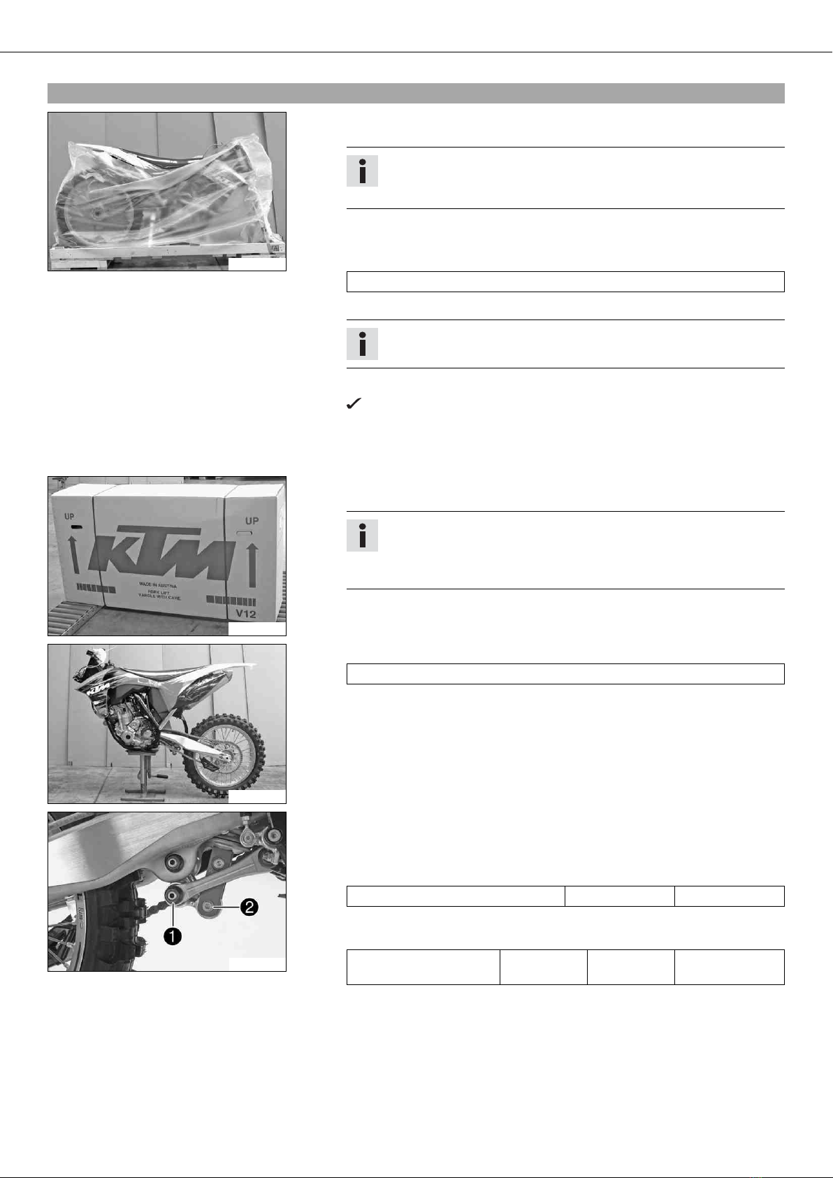
Packaging 2
–Remove the box and the plastic packaging.
Info
To avoid damaging the motorcycle during the setup, leave the protective
film on the vehicle until you have finished.
–Remove the separate enclosure and unpack it. Check that the scope of delivery
is complete on the basis of the enclosed packing list.
–Have a lift stand available.
Lift stand (54829055000)
–Carefully loosen and remove the tensioning belt over the link fork.
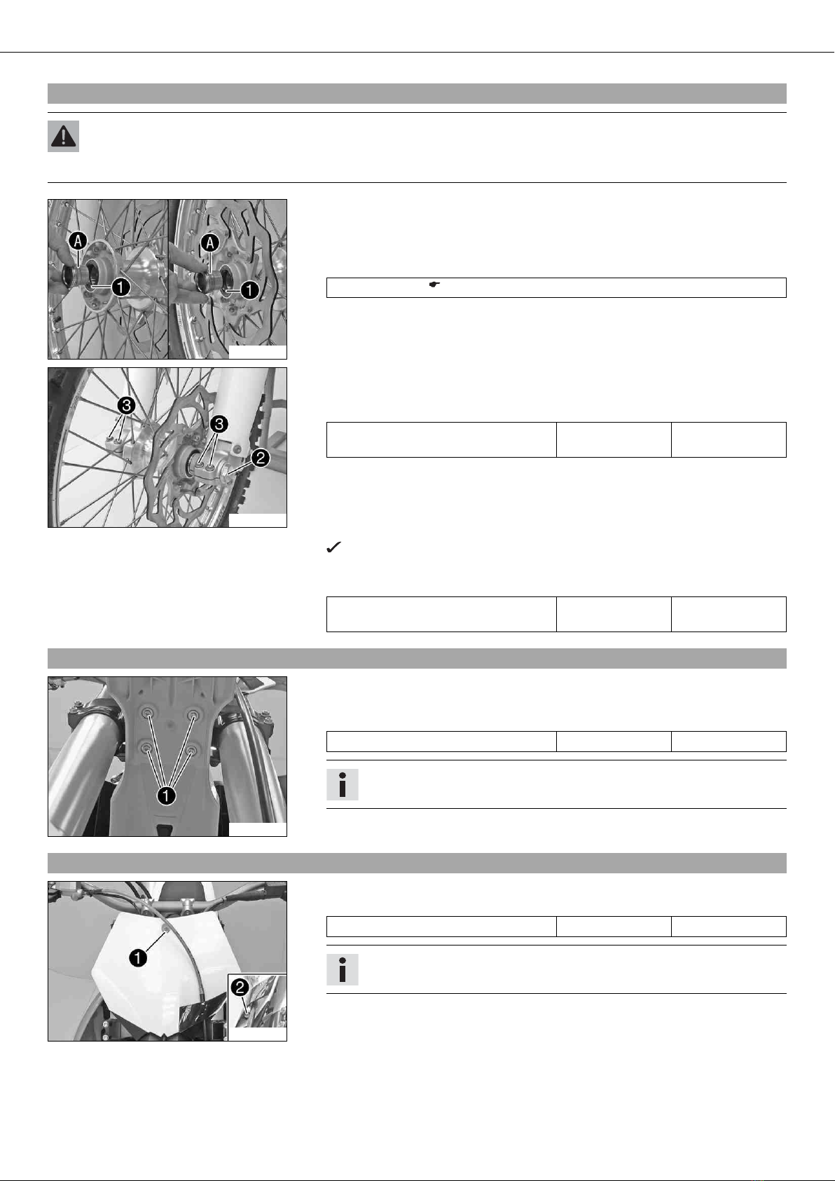
Info
An assistant prevents the motorcycle from falling over.
–Carefully loosen and remove the tensioning belts around the lower triple clamp.
The vehicle is released at the front.
–Together with an assistant, take the vehicle off of the palette.
–Position the vehicle on a lift stand.
–Check the vehicle for transport damage.
B00532-01
Package 12
–Remove the box and the plastic packaging.
Info
An assistant prevents the motorcycle from falling over.
To avoid damaging the motorcycle during the setup, leave the protective
film on the vehicle until you have finished.
–Remove the separate enclosure and unpack it. Check that the scope of delivery
is complete on the basis of the enclosed packing list.
B00533-01
–Have a lift stand available.
Lift stand (54829055000)
–Together with an assistant, take the vehicle off of the palette.
–Position the vehicle on a lift stand.
–Check the vehicle for transport damage.
101014-10
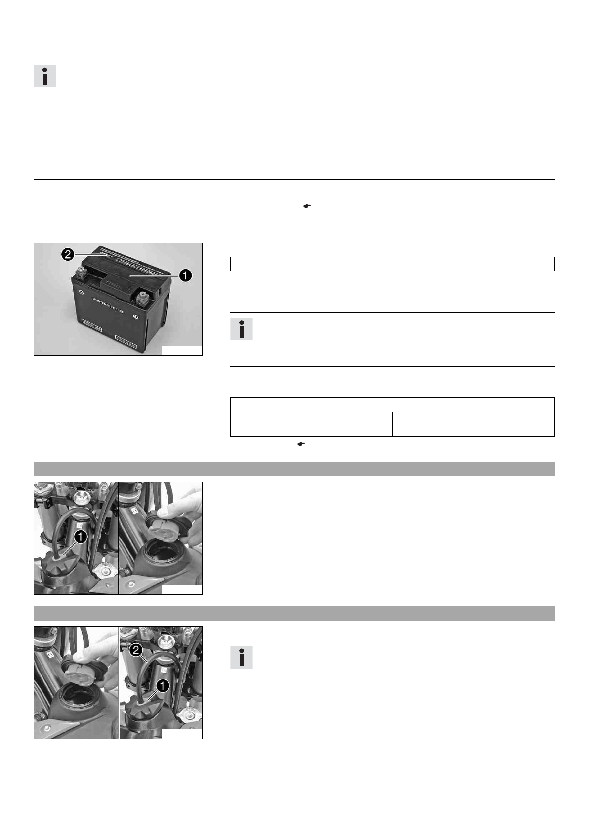
–Remove the cardboard from around the shock absorber.
–Position the angle lever and linkage lever.
–Mount and tighten screw cap .
Guideline
Nut, linkage lever to angle lever M14x1.5 80 Nm (59 lbf ft)
–Mount and tighten screw .
Guideline
Screw, bottom shock
absorber
M10 60 Nm
(44.3 lbf ft)
Loctite®243™


 Supplementary service manual")