WORK 7
Info
Even when there is no load on the battery, it still loses power steadily.
The charge state and the type of charge are very important for the service life of the battery.
Rapid recharging with a high charging current shortens the battery's service life.
If the charging current, charging voltage and charging time are exceeded, electrolyte escapes through the safety valves. This
reduces the battery capacity.
If the battery is depleted from starting the vehicle repeatedly, the battery must be charged immediately.
If the battery is left in a discharged state for an extended period, it will become over-discharged and sulfate, destroying the
battery.
The battery is maintenance-free, which means that the acid level does not need to be checked.
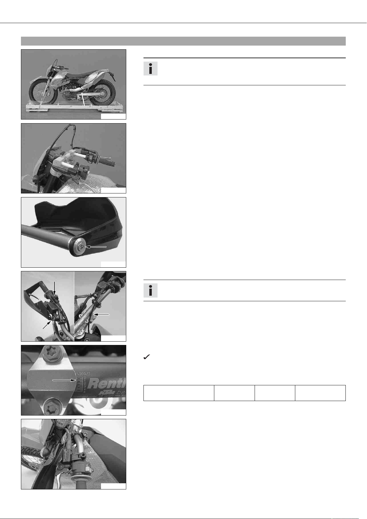
–Switch off all power consumers and switch off the engine.
–Remove the battery. ( p. 7)
100151-10
–Connect the battery charger to the battery. Switch on the battery charger.
Battery charger (58429074000)
You can also use the battery charger to test rest potential and start potential of the
battery, and to test the alternator. With this device, you cannot overcharge the bat-
tery.
Info
Never remove lid .
Charge the battery with a maximum of 10% of the capacity specified on the
battery housing .
–Switch off and disconnect the charger after charging.
Guideline
The charge current, charge voltage and charge time must not be exceeded.
Charge the battery regularly when the
motorcycle is not in use
3 months
–Install the battery. ( p. 8)
3.4Removing the battery
Warning
Risk of injury Battery acid and battery gases cause serious cauterization.
–Keep batteries out of the reach of children.
–Wear suitable protective clothing and goggles.
–Avoid contact with battery acid and battery gases.
–Keep the battery away from sparks or open fire. Charge only in well ventilated rooms.
–In the event of skin contact, rinse with large amounts of water. If battery acid gets in the eyes, rinse with water for at least
15 minutes and contact a doctor.
–Switch off all power consumers and switch off the engine.
–Remove the seat. ( p. 6)
100277-10
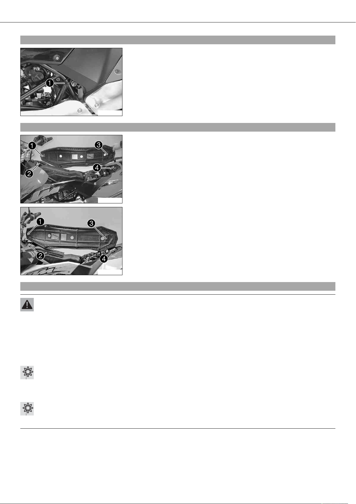
–Disconnect the negative (minus) cable of the battery.
–Pull off the plug connector upwards.
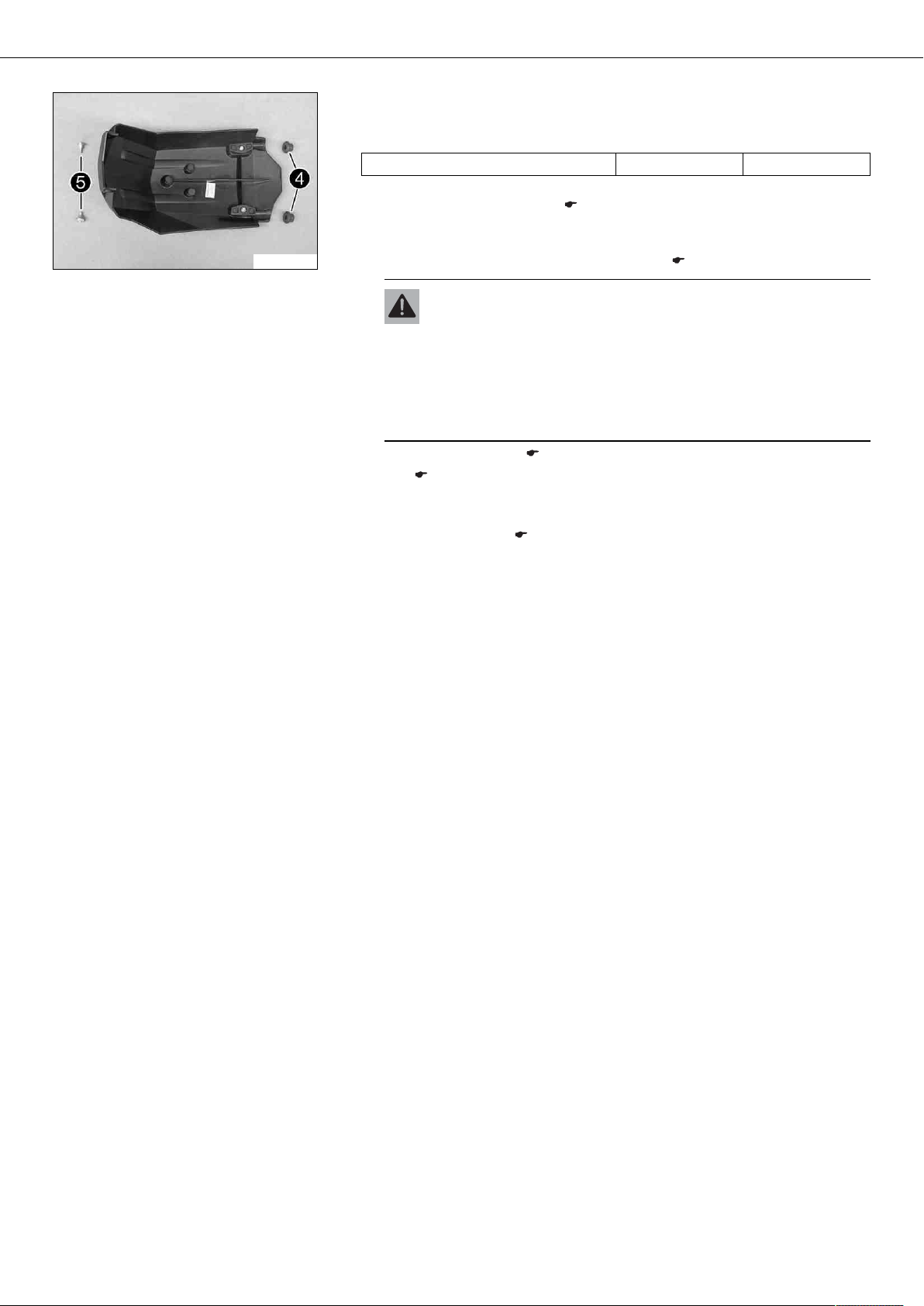
–Remove screws .
–Pull the retaining bracket of the battery forward and remove it.
–Take off the positive pole cover .
–Disconnect the positive (plus) cable of the battery.
–Push the wiring harness to the side and pull the battery out of the battery rack.
Info
Never operate the motorcycle with a discharged battery or without a battery.
In both cases, electrical components and safety devices can be damaged.
The vehicle is therefore no longer roadworthy.


 Supplementary service manual")