3 WORK
8
Note
Environmental hazard Hazardous substances cause environmental damage.
–Dispose of oils, grease, filters, fuel, cleaning agents, brake fluid, etc., correctly and in compliance with
the applicable regulations.
Info
Even when there is no load on the battery, it discharges steadily.
The charging level and the method of charging are very important for the service life of the battery.
Rapid recharging with a high charging current shortens the service life of the battery.
If the charging current, charging voltage, and charging time are exceeded, the battery will be destroyed.
If the battery is depleted from starting the vehicle repeatedly, the battery must be charged immediately.
If the battery is left in a discharged state for an extended period, it will become over-discharged and sul-
fated, destroying the battery.
The battery is maintenance-free, i.e., the acid level does not have to be checked.
Preparatory work
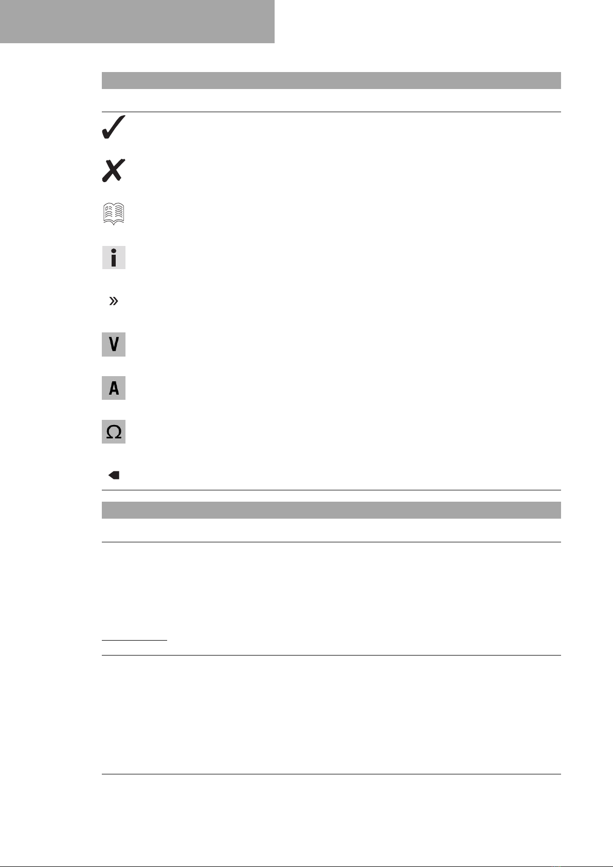
–Switch off the ignition by turning the ignition key to the posi-
tion .
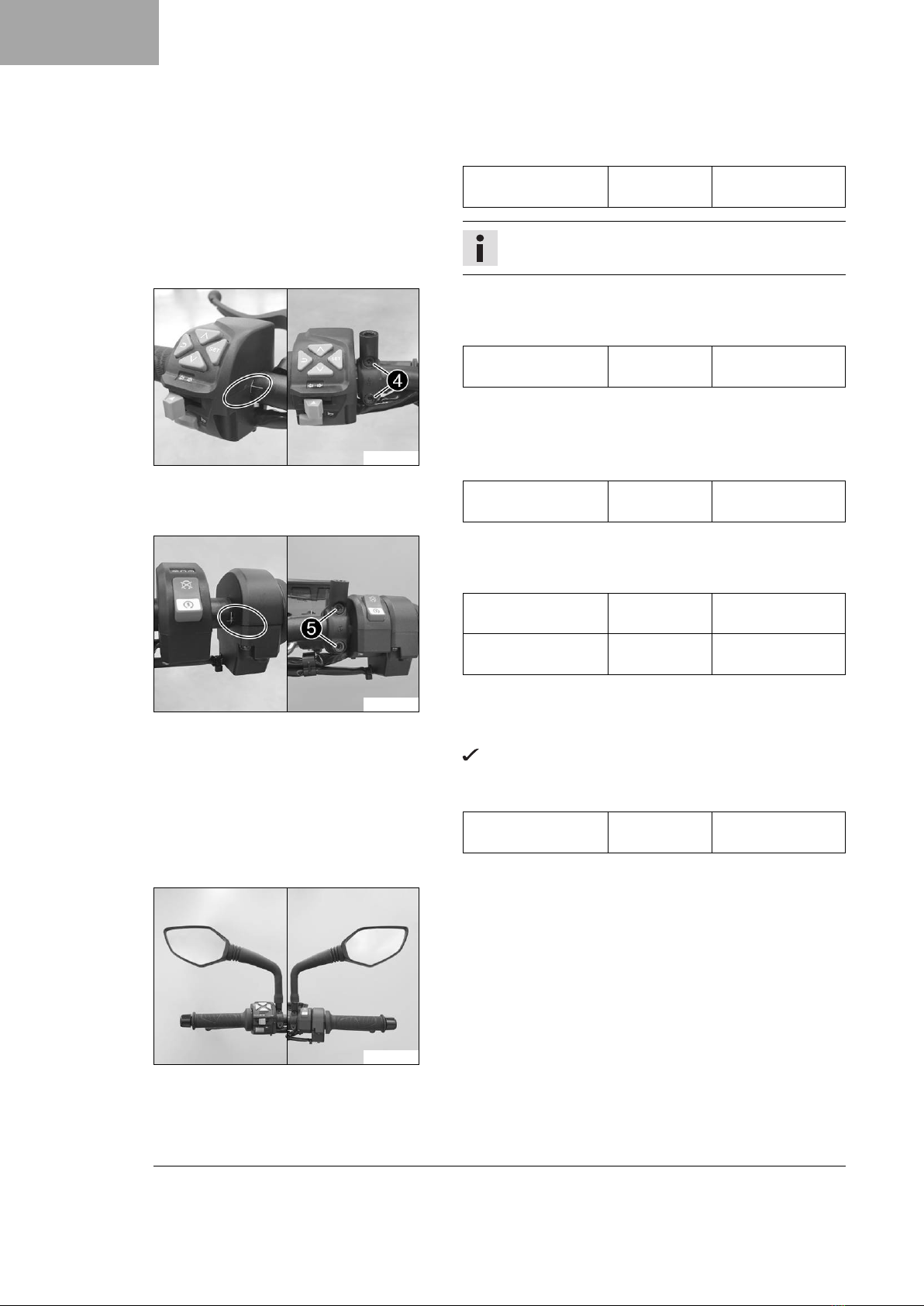
–Remove the passenger seat. ( p. 7)
–Disconnect the negative cable of the battery. ( p. 9)
311910-10
Main work
–Connect the battery charger to the battery. Adjust the battery
charger.
EU battery charger XCharge-professional (00029095050)
Alternative 1
US battery charger XCharge-professional
(00029095051)
Alternative 2
UK battery charger XCharge-professional
(00029095052)
Alternative 3
CH battery charger XCharge-professional
(00029095053)
Info
Follow the instructions of the charger and the manual.
–Disconnect the battery charger after charging the battery.
Guideline
The charging current, charging voltage, and charging time
must not be exceeded.
Charge the battery regularly
when the motorcycle is not
in use
3 months
Finishing work
–Connect the negative cable of the battery. ( p. 9)
–Mount the passenger seat. ( p. 7)
–Adjust the time and date.


 Supplementary service manual")