KTM Freeride 350 EU Manual

SETUP INSTRUCTIONS 2014
Freeride 350 EU
Freeride 350 AUS
Art. no. 3213148en


INTRODUCTION 1
INTRODUCTION
The work described in these setup instructions must be performed before the vehicle is delivered to the customer.
Read the setup instructions in their entirety before beginning work.
Print out the current PDI form found on the KTM DEALER.NET.
These setup instructions were written to correspond to the latest state of this series. We reserve the right to make changes in the inter-
est of technical advancement without at the same time updating this manual.
We shall not provide a description of general workshop methods. Likewise, safety rules that apply in a workshop are not specified here.
It is assumed that the work will be performed by a fully trained mechanic.
All specifications are non-binding. KTM Sportmotorcycle AG specifically reserves the right to modify or delete technical specifica-
tions, prices, colors, forms, materials, services, designs, equipment, etc., without prior notice and without specifying reasons, to adapt
these to local conditions, as well as to stop production of a particular model without prior notice. KTM accepts no liability for delivery
options, deviations from illustrations and descriptions, as well as misprints and other errors. The models portrayed partly contain spe-
cial equipment that does not belong to the regular scope of supply.
© 2014 KTM-Sportmotorcycle AG, Mattighofen Austria
All rights reserved
Reproduction, even in part, as well as copying of all kinds, is permitted only with the express written permission of the copyright
owner.
ISO 9001(12 100 6061)
According to the international quality management standard ISO 9001, KTM uses quality assurance processes that lead
to the maximum possible quality of the products.
Issued by: TÜV Management Service
KTM-Sportmotorcycle AG
5230 Mattighofen, Austria

1 MEANS OF REPRESENTATION 2
1.1 Symbols used
The meaning of specific symbols is described below.
Indicates an expected reaction (e.g. of a work step or a function).
Indicates an unexpected reaction (e.g. of a work step or a function).
Indicates a page reference (more information is provided on the specified page).
Indicates information with more details or tips.
Indicates the result of a testing step.
Denotes a voltage measurement.
Denotes a current measurement.
Denotes a resistance measurement.
1.2 Formats used
The typographical formats used in this document are explained below.
Proprietary name Identifies a proprietary name.
Name®Identifies a protected name.
Brand™ Identifies a trademark.

2 SAFETY ADVICE 3
2.1 Work rules
Special tools are necessary for certain tasks. The tools are not contained in the vehicle but can be ordered under the number in paren-
theses. E.g.: bearing puller (15112017000)
During assembly, non-reusable parts (e.g. self-locking screws and nuts, seals and seal rings, O-rings, pins, lock washers) must be
replaced by new parts.
In some instances, a thread locker (e.g. Loctite®) is required. The manufacturer instructions for use must be followed.
After disassembly, clean the parts that are to be reused and check them for damage and wear. Change damaged or worn parts.
After you complete the repair or service work, check the operating safety of the vehicle.
2.2 Safety advice
A number of safety instructions need to be followed to operate the vehicle safely. Therefore, read this manual carefully. The safety
instructions are highlighted in the text and are referred to at the relevant passages.
Info
The vehicle has various information and warning labels at prominent locations. Do not remove information/warning labels. If
they are missing, you or others may not recognize dangers and may therefore be injured.
2.3 Degrees of risk and symbols
Danger
Identifies a danger that will immediately and invariably lead to fatal or serious permanent injury if the appropriate measures
are not taken.
Warning
Identifies a danger that is likely to lead to fatal or serious injury if the appropriate measures are not taken.
Note
Identifies a danger that will lead to considerable machine and material damage if the appropriate measures are not taken.
Warning
Identifies a danger that will lead to environmental damage if the appropriate measures are not taken.
2.4 Operating and auxiliary substances
Warning
Environmental hazard Improper handling of fuel is a danger to the environment.
–Do not allow fuel to get into the ground water, the ground, or the sewage system.
Use the operating and auxiliary substances (such as fuel and lubricants) as specified in the manual.

3 SETUP 4
3.1 Unpacking and setting up the vehicle
B01160-01
Packaging 2
–Remove the box and the plastic packaging.
Info
An assistant prevents the motorcycle from falling over.
To avoid damaging the motorcycle during the setup, leave the protective
film on the vehicle until you have finished.
–Remove the separate enclosure and unpack it. Check that the scope of supply
is complete on the basis of the enclosed packing list.
–Have a lift stand available.
Lift stand (54829055000)
–Carefully loosen and remove the tension belt of the footrest bracket.
Info
An assistant prevents the motorcycle from falling over.
402050-01
–Together with an assistant, take the vehicle off the palette.
–Position the vehicle on a lift stand.
–Check the vehicle for transport damage.
B01161-01
Package 12
–Remove the box and the plastic packaging.
Info
An assistant prevents the motorcycle from falling over.
To avoid damaging the motorcycle during the setup, leave the protective
film on the vehicle until you have finished.
–Remove the separate enclosure and unpack it. Check that the scope of supply
is complete on the basis of the enclosed packing list.
–Have a lift stand available.
Lift stand (54829055000)
–Together with an assistant, take the vehicle off the palette.
–Position the vehicle on a lift stand.
–Check the vehicle for transport damage.
402051-01
–Install the shock absorber. ( p. 9)

3 SETUP 5
B01163-01
–Route the clutch line with the clutch master cylinder toward the front between
the upper and lower triple clamps.
–Position the fork legs and tighten the screws of the triple clamp.
Guideline
Screw, top triple clamp M8 22 Nm
(16.2 lbf ft)
Screw, bottom triple clamp M8 18 Nm
(13.3 lbf ft)
Info
The lowest milled groove in the fork leg must be flush with the top edge
of the upper triple clamp.
Position the bleeder screws toward the front.
0
0
B01036-10
–Remove screws . Take off the handlebar clamps.
–Remove screws . Remove the handlebar holders.
–Place the handlebar holders in the required position. Mount and tighten
screws .
Guideline
Screw, handlebar support M10 40 Nm
(29.5 lbf ft)
Loctite®243™
Info
Position the left and right handlebar holders evenly.
B01164-01
–Position the handlebar.
Info
Make sure the cables and wiring are positioned correctly.
–Position the handlebar clamps. Mount and tighten the screws evenly.
Guideline
Screw, handlebar clamp M8 20 Nm
(14.8 lbf ft)
Info
The markings on the handlebar should be at the center of the handlebar
clamps.
Keep the gap widths equal when tightening.
–Install the front wheel. ( p. 10)
–Mount the handlebar cushion.
B01994-01
–Position the controls on the right half of the handlebar.
Info
The routing of the cables is shown in the figure.
B01993-01
–Position the controls on the left half of the handlebar.
Info
The figure shows how to route the clutch line and wiring harness.

3 SETUP 6
B01991-10
–Mount the connector retainer and speedometer on the upper triple clamp.
Guideline
Remaining screws, chassis M6 10 Nm (7.4 lbf ft)
–Position the turn signal indicator lamp .
–Connect all plug-in connectors to the connector retainer.
B01992-10
–Remove the fuel tank. ( p. 11)
–Pull the EFI control unit from the holder and set it to one side.
–Take off the electrical compartment.
–Disconnect the plug-in connector from the main wiring harness.
–Connect the plug-in connector of the turn signal wiring harness with the plug-in
connector of the main wiring harness.
B01176-01
–Position the turn signal wiring harness against the main wiring harness and secure
with cable binders.
Info
The routing of the wiring harness is shown in the figure.
–Mount the electrical compartment.
–Position the EFI control unit.
–Install the fuel tank. ( p. 12)
401382-01
–Mount the turn signal switch and connect the plug-in connector with the wiring har-
ness.

3 SETUP 7
B01995-10
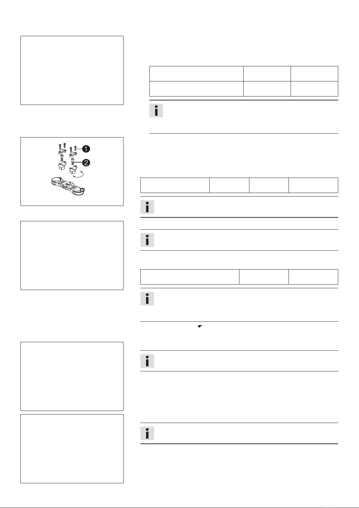
–Insert the black and violet cables of bulb included in the separate enclosure into
the socket and position it in the turn signal indicator lamp .
–Position the turn signal on each side and mount and tighten nuts .
–Connect the plug-in connector of the right turn signal with the connector
marked green on the wiring harness.
–Connect the plug-in connector of the left turn signal with the connector marked
red on the wiring harness.
–Mount the turn signal relay with the retaining bracket and plug in the connec-
tor.
–Install the front fender. ( p. 16)
–Refit the headlight mask with the headlight. ( p. 16)
800042-10
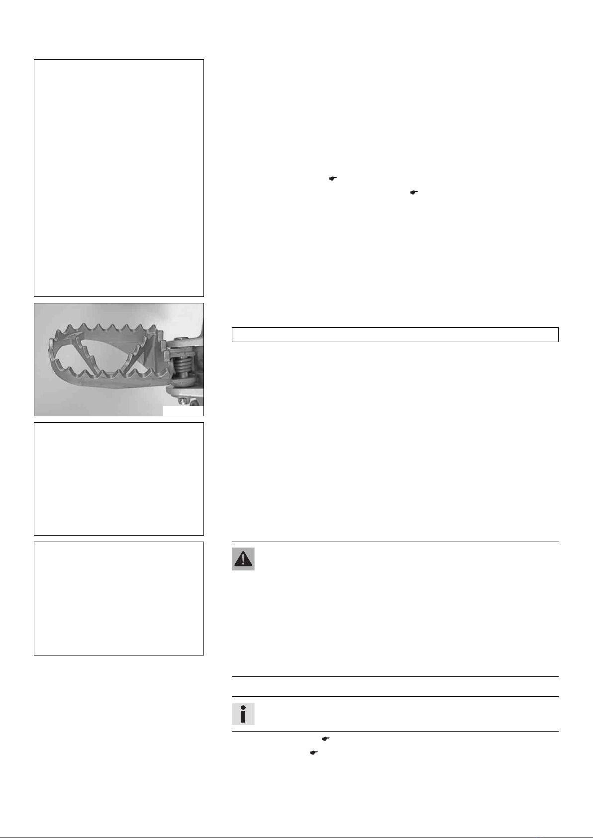
–Mount the footrests with the springs and pins. Secure the pins using the washers
and cotter pins.
Pliers for footrest spring (58429083000)
B01170-01
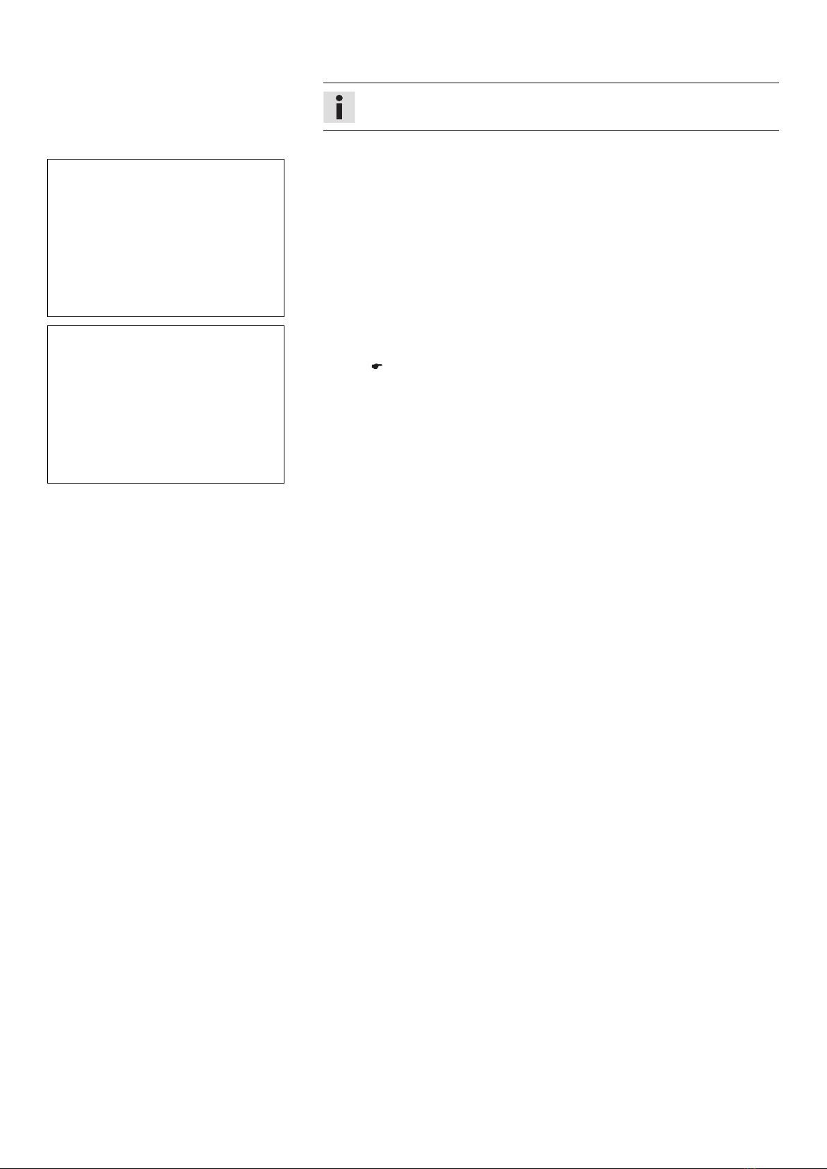
–Mount the license plate holder with the license plate lamp, turn signals, and reflec-
tor.
–Connect the electrical components.
–Connect the plug-in connector of the right turn signal with the connector marked
green on the wiring harness.
–Connect the plug-in connector of the left turn signal with the connector marked red
on the wiring harness.
B01173-01
Warning
Risk of injury Battery acid and battery gases cause serious chemical burns.
–Keep batteries out of the reach of children.
–Wear suitable protective clothing and goggles.
–Avoid contact with battery acid and battery gases.
–Keep sparks and open flames away from the battery. Only charge in
well-ventilated rooms.
–In the event of skin contact, rinse with large amounts of water. If battery
acid gets in the eyes, rinse with water for at least 15 minutes and con-
tact a physician.
–Fill the battery.
Info
Read the notes in the battery package.
–Recharge the battery. ( p. 14)
–Install the battery. ( p. 15)
–Unpack and mount the KTM PowerParts included in the delivery (optional).

3 SETUP 8
Info
Read the accompanying KTM PowerParts fitting instructions.
–Apply the label included in the delivery (optional).
B01172-01
–Mount the mirror clamps on both sides.
B01171-01
–Mount and tighten the rear mirror on both sides.
–Position all controls in their exact positions on the handlebar. Tighten all screws.
–Refuel. ( p. 18)
–Print out the current PDI form found on KTM DEALER.NET and perform the delivery
inspection.

4 SERVICE WORK ON THE CHASSIS 9
4.1 Raising the motorcycle with the lift stand
Note
Danger of damage The parked vehicle may roll away or fall over.
–Always place the vehicle on a firm and even surface.
B01029-10
–Raise the motorcycle at the frame underneath the engine.
Lift stand (54829055000)
The wheels must no longer touch the ground.
–Secure the motorcycle against falling over.
4.2 Removing the motorcycle from the lift stand
Note
Danger of damage The parked vehicle may roll away or fall over.
–Always place the vehicle on a firm and even surface.
602798-10
–Remove the motorcycle from the lift stand.
–Remove the lift stand.
–To park the motorcycle, fold side stand down to the ground with your foot and
rest the motorcycle on it.
Info
While riding, the side stand must be folded up and secured with the rubber
band.
4.3 Installing the shock absorber
B01053-11
Main work
–Push splash protector to the side and position the shock absorber. Mount and
tighten screw .
Guideline
Screw, top shock absorber M12 80 Nm
(59 lbf ft)
Loctite®243™
–Mount and tighten screw .
Guideline
Screw, bottom shock
absorber
M12 80 Nm
(59 lbf ft)
Loctite®243™
Info
The heim joint for the shock absorber at the swing arm is Teflon coated. It
must not be greased with grease or with other lubricants. Lubricants dis-
solve the Teflon coating, thereby drastically reducing the service life.
–Mount and tighten screw .
Guideline
Screw, upper subframe M10 45 Nm
(33.2 lbf ft)
Loctite®243™
Finishing work
–Lock the seat. ( p. 11)
–Remove the motorcycle from the lift stand. ( p. 9)

4 SERVICE WORK ON THE CHASSIS 10
4.4 Installing the front wheel
Warning
Danger of accidents Reduced braking efficiency due to oil or grease on the brake discs.
–Always keep the brake discs free of oil and grease, and clean them with brake cleaner when necessary.
B01046-11
–Check the wheel bearing for damage and wear.
» If the wheel bearing is damaged or worn:
–Change the wheel bearing.
–Clean and grease the shaft seal rings and contact surface of the spacers.
Long-life grease ( p. 22)
–Insert the spacers.
B01044-11
–Position the front wheel and insert the wheel spindle.
The brake linings are correctly positioned.
–Mount and tighten screw .
Guideline
Screw, front wheel spindle M20x1.5 35 Nm
(25.8 lbf ft)
–Activate the hand brake lever multiple times until the brake linings are in contact
with the brake disc.
–Remove the motorcycle from the lift stand. ( p. 9)
–Pull the front wheel brake and push down hard on the fork several times to align
the fork legs.
–Tighten screw .
Guideline
Screw, fork stub M8 15 Nm
(11.1 lbf ft)
4.5 Folding the seat up
B01021-10
–Press release lever .
–Lift the seat and fold it up.

4 SERVICE WORK ON THE CHASSIS 11
4.6 Locking the seat
B01022-10
–Fold down the seat and push it down.
The seat engages with an audible click.
–Finally, check that the seat is correctly locked.
4.7 Removing the fuel tank
Danger
Fire hazard Fuel is highly flammable.
–Never refuel the vehicle near open flames or burning cigarettes, and always switch off the engine first. Be careful that no
fuel is spilt, especially on hot vehicle components. Clean up spilt fuel immediately.
–The fuel in the fuel tank expands when warm and may emerge if overfilled. Follow the instructions on refueling.
Warning
Danger of poisoning Fuel is poisonous and a health hazard.
–Fuel must not come into contact with the skin, eyes, or clothing. Do not breathe in the fuel vapors. If contact occurs with
the eyes, rinse with water immediately and contact a physician. Immediately clean contaminated areas on the skin with
soap and water. If fuel is swallowed, contact a physician immediately. Change clothing that is contaminated with fuel.
Store fuel properly in a suitable canister and keep away from children.
Preparatory work
–Fold the seat up. ( p. 10)
B01074-10
Main work
–Thoroughly clean the plug-in connection of the fuel line using compressed air.
Info
Under no circumstances should dirt enter the fuel line. Dirt in the fuel line
clogs the injection valve.
–Disconnect the plug-in connection of the fuel line.
–Mount wash cap set .
Wash cap set (81212016000)
B01075-10
–Remove the tube from the fuel tank breather.
–Remove screws on both sides.
–Remove screw .
B01076-10
–Disconnect connector .
–Pull off engine breather hose .

4 SERVICE WORK ON THE CHASSIS 12
B01077-10
–Release hose clamp .
–Detach the intake flange from the throttle valve body.
B01078-10
–Pull up the fuel tank slightly and disconnect connector of the fuel pump.
–Remove the fuel tank from above.
4.8 Installing the fuel tank
Danger
Fire hazard Fuel is highly flammable.
–Never refuel the vehicle near open flames or burning cigarettes, and always switch off the engine first. Be careful that no
fuel is spilt, especially on hot vehicle components. Clean up spilt fuel immediately.
–The fuel in the fuel tank expands when warm and may emerge if overfilled. Follow the instructions on refueling.
Warning
Danger of poisoning Fuel is poisonous and a health hazard.
–Fuel must not come into contact with the skin, eyes, or clothing. Do not breathe in the fuel vapors. If contact occurs with
the eyes, rinse with water immediately and contact a physician. Immediately clean contaminated areas on the skin with
soap and water. If fuel is swallowed, contact a physician immediately. Change clothing that is contaminated with fuel.
B01078-11
Main work
–Check the throttle cable routing. ( p. 13)
–Make sure that no cables are trapped or damaged.
–Attach connector of the fuel pump.
B01077-11
–Position the fuel tank.
–Position the intake flange on the throttle valve body.
–Tighten hose clamp .

4 SERVICE WORK ON THE CHASSIS 13
B01076-11
–Plug in connector .
–Position engine breather hose .
B01075-11
–Mount and tighten screws on both sides.
Guideline
Screw, fuel tank M8 15 Nm
(11.1 lbf ft)
Loctite®243™
–Mount and tighten screw .
Guideline
Remaining screws, chassis M6 10 Nm (7.4 lbf ft)
–Mount the fuel tank breather.
B01079-10
–Thoroughly clean the plug-in connection of the fuel line using compressed air.
Info
Under no circumstances should dirt enter into the fuel line. Dirt in the fuel
line clogs the injection valve.
–Remove the wash cap set. Lubricate the O-ring and connect plug-in connection
of the fuel line.
Info
Route the cable and fuel line at a safe distance from the exhaust system.
Finishing work
–Lock the seat. ( p. 11)
4.9 Checking the throttle cable routing
Preparatory work
–Fold the seat up. ( p. 10)
–Remove the fuel tank. ( p. 11)
B01080-10
Main work
–Check the throttle cable routing.
Both throttle cables must be routed to the throttle valve body side by side behind
the handlebars and below the seat fixing.
» If the throttle cable is not routed as specified:
–Correct the throttle cable routing.
Finishing work
–Install the fuel tank. ( p. 12)
–Lock the seat. ( p. 11)

4 SERVICE WORK ON THE CHASSIS 14
4.10 Recharging the battery
Warning
Risk of injury Battery acid and battery gases cause serious chemical burns.
–Keep batteries out of the reach of children.
–Wear suitable protective clothing and goggles.
–Avoid contact with battery acid and battery gases.
–Keep sparks and open flames away from the battery. Only charge in well-ventilated rooms.
–In the event of skin contact, rinse with large amounts of water. If battery acid gets in the eyes, rinse with water for at least
15 minutes and contact a physician.
Warning
Environmental hazard The battery contains elements that are harmful to the environment.
–Do not discard batteries with the household waste. Dispose of faulty batteries in an environmentally compatible manner.
Give the battery to your authorized KTM dealer or dispose of it at a collection point for used batteries.
Warning
Environmental hazard Hazardous substances cause environmental damage.
–Oil, grease, filters, fuel, cleaners, brake fluid, etc., should be disposed of as stipulated in applicable regulations.
Info
Even when there is no load on the battery, it discharges steadily.
The charge state and the type of charge are very important for the service life of the battery.
Rapid recharging with a high charging current shortens the battery's service life.
If the charging current, charging voltage, and charging time are exceeded, electrolyte escapes through the safety valves. This
reduces the battery capacity.
If the battery is depleted from starting the vehicle repeatedly, the battery must be charged immediately.
If the battery is left in a discharged state for an extended period, it will become over-discharged and sulfate, destroying the
battery.
The battery is maintenance-free, i.e., the acid level does not have to be checked.
Preparatory work
–Remove the battery. ( p. 15)
400240-10
Main work
–Connect the battery charger to the battery. Switch on the battery charger.
Battery charger (58429074000)
You can also use the battery charger to test the rest potential and starting ability of
the battery, and to test the alternator. With this device, you cannot overcharge the
battery.
Info
Never remove lid .
Charge the battery with a maximum of 10% of the capacity specified on the
battery housing .
–Switch off the charger after charging. Disconnect the battery.
Guideline
The charging current, charging voltage, and charging time must not be exceeded.
Charge the battery regularly when the
motorcycle is not in use
3 months
Finishing work
–Install the battery. ( p. 15)

4 SERVICE WORK ON THE CHASSIS 15
4.11 Removing the battery
Warning
Risk of injury Battery acid and battery gases cause serious chemical burns.
–Keep batteries out of the reach of children.
–Wear suitable protective clothing and goggles.
–Avoid contact with battery acid and battery gases.
–Keep sparks and open flames away from the battery. Only charge in well-ventilated rooms.
–In the event of skin contact, rinse with large amounts of water. If battery acid gets in the eyes, rinse with water for at least
15 minutes and contact a physician.
B01102-10
–Switch off all power consumers and switch off the engine.
–Remove screw .
–Remove fastening plate .
B01103-10
–Remove the battery from the battery compartment.
–Disconnect negative cable from the battery.
–Pull back positive terminal cover and disconnect the positive cable from the
battery.
4.12 Installing the battery
B01104-10
–Position the positive cable and mount and tighten the screw.
Guideline
Screw, battery terminal M5 2.5 Nm
(1.84 lbf ft)
–Slide positive terminal cover over the positive terminal.
–Position the negative cable and mount and tighten the screw.
Guideline
Screw, battery terminal M5 2.5 Nm
(1.84 lbf ft)
Battery (YTX5L-BS)
Info
Contact disk must be mounted between screw and cable socket
with the claws facing down.

4 SERVICE WORK ON THE CHASSIS 16
B01102-11
–Position the battery in the battery compartment.
–Attach fixing flap .
–Mount and tighten screw .
4.13 Installing the front fender
B01030-10
–Ensure that the spacers are mounted in the fender.
–Position the front fender. Mount and tighten screws .
Guideline
Remaining screws, chassis M6 10 Nm (7.4 lbf ft)
Info
Make sure the holding lugs engage in the headlight mask.
4.14 Refitting the headlight mask with the headlight
602812-11
Main work
–Connect connector of the headlight and turn signals.
B01041-11
–Position the headlight mask and fix it with the rubber band .
Info
Make sure that the holding lugs engage in the fender.
–Position the brake line and wiring harness .
Finishing work
–Check the headlight setting. ( p. 17)

4 SERVICE WORK ON THE CHASSIS 17
4.15 Checking the headlight setting
0
0
AA
0
0
BB
400726-10
–Position the vehicle upright on a horizontal surface in front of a light wall and make
a mark at the height of the center of the low beam headlight.
–Make another mark at a distance under the first mark.
Guideline
Distance 5 cm (2 in)
–Position the vehicle vertically a distance away from the wall.
Guideline
Distance 5 m (16 ft)
–The rider now sits down on the motorcycle.
–Switch on the low beam.
–Check the headlight setting.
The boundary between light and dark must be exactly on the lower mark for a
motorcycle with driver.
» If the boundary between light and dark does not meet specifications:
–Adjust the headlight range. ( p. 17)
4.16 Adjusting the headlight range
Preparatory work
–Check the headlight setting. ( p. 17)
B01043-10
Main work
–Adjust the beam distance of the headlight by turning screw .
Guideline
For a motorcycle with rider, the light/dark boundary must be exactly on the lower
mark (the mark is created in: Checking the headlight setting).
Info
Turn clockwise to increase the headlight range, turn counterclockwise to
reduce the headlight range.
A change in weight on the vehicle may require a correction of the headlight
range.
4.17 Opening the filler cap
Danger
Fire hazard Fuel is highly flammable.
–Never refuel the vehicle near open flames or burning cigarettes, and always switch off the engine first. Be careful that no
fuel is spilt, especially on hot vehicle components. Clean up spilt fuel immediately.
–The fuel in the fuel tank expands when warm and may emerge if overfilled. Follow the instructions on refueling.
Warning
Danger of poisoning Fuel is poisonous and a health hazard.
–Fuel must not come into contact with the skin, eyes, or clothing. Do not breathe in the fuel vapors. If contact occurs with
the eyes, rinse with water immediately and contact a physician. Immediately clean contaminated areas on the skin with
soap and water. If fuel is swallowed, contact a physician immediately. Change clothing that is contaminated with fuel.
Store fuel properly in a suitable canister and keep away from children.
Warning
Environmental hazard Improper handling of fuel is a danger to the environment.
–Do not allow fuel to get into the ground water, the ground, or the sewage system.
Preparatory work
–Fold the seat up. ( p. 10)

4 SERVICE WORK ON THE CHASSIS 18
602796-10
Main work
–Press release button , turn the filler cap counterclockwise, and lift it free.
4.18 Closing the filler cap
602797-10
Main work
–Replace the filler cap and turn clockwise until the release button locks in
place.
Info
Run the fuel tank breather hose without kinks.
Finishing work
–Lock the seat. ( p. 11)
4.19 Refueling
Danger
Fire hazard Fuel is highly flammable.
–Never refuel the vehicle near open flames or burning cigarettes, and always switch off the engine first. Be careful that no
fuel is spilt, especially on hot vehicle components. Clean up spilt fuel immediately.
–The fuel in the fuel tank expands when warm and may emerge if overfilled. Follow the instructions on refueling.
Warning
Danger of poisoning Fuel is poisonous and a health hazard.
–Fuel must not come into contact with the skin, eyes, or clothing. Do not breathe in the fuel vapors. If contact occurs with
the eyes, rinse with water immediately and contact a physician. Immediately clean contaminated areas on the skin with
soap and water. If fuel is swallowed, contact a physician immediately. Change clothing that is contaminated with fuel.
Note
Material damage Premature clogging of the fuel filter.
–In some countries and regions, the available fuel quality and cleanliness may not be sufficient. This will result in problems with
the fuel system.
–Only refuel with clean fuel that meets the specified standards.
Warning
Environmental hazard Improper handling of fuel is a danger to the environment.
–Do not allow fuel to get into the ground water, the ground, or the sewage system.
Preparatory work
–Switch off the engine.
–Fold the seat up. ( p. 10)
–Open the filler cap. ( p. 17)
Other manuals for Freeride 350 EU
2
This manual suits for next models
1
Table of contents
Other KTM Motorcycle manuals

KTM
KTM 620 2001 User guide

KTM
KTM 1290 Super Adventure User manual

KTM
KTM 690 Enduro R EU User manual

KTM
KTM 250 SX-F EU Manual

KTM
KTM 125 SX EU 2014 Manual

KTM
KTM 125 DUKE EU User manual

KTM
KTM 350 SX-F EU 2014 Manual

KTM
KTM 450 XC-F User manual

KTM
KTM 400 SX RACING 2000 User guide

KTM
KTM 65 SX 1999 User manual

KTM
KTM EXC 200 EXC User manual

KTM
KTM 125 SX 2018 User manual

KTM
KTM 85 SX 2023 User manual

KTM
KTM TC 50 2020 User manual

KTM
KTM 60 65 SX User manual

KTM
KTM Freeride E-XC NG 2018 User manual

KTM
KTM F8475S0 2019 User manual

KTM
KTM 250 SX-F 2021 User manual

KTM
KTM 690 Enduro R EU User manual

KTM
KTM 690 Duke EU 2014 Manual