Kuppersbusch GH 606.0 E User manual

Gas cookers GHK606.0 E
GHK506.0 E
GHK505.0 E
GKH 507.0 E
GB

Technical manual: H2-120-61-01
Responsable: Kirchmaier Küppersbusch Vertriebsges. mbH
Tel.: (0209) 401-718 Kundendienst
Fax: (0209) 401-743 Postfach 100 132
Date: 27.07.1998 45801 Gelsenkirchen

Contents
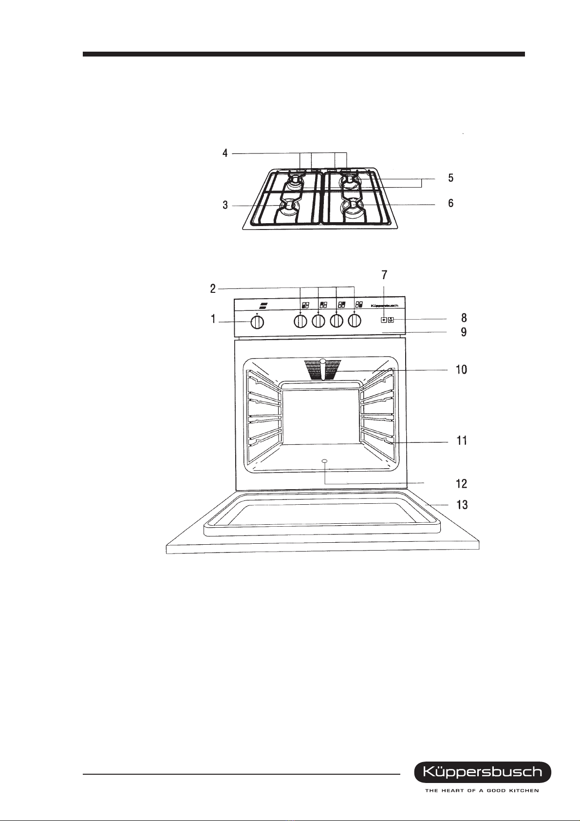
1. Your appliance at a glance ...........................................................................................................4
1.1 GH 606.0 E............................................................................................................................4
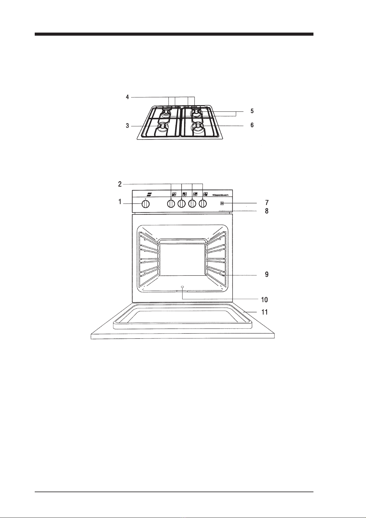
1.2 GH 506.0 E............................................................................................................................5
1.3 GH 505.0 E............................................................................................................................6
1.4 GKH 507.0 E .........................................................................................................................7
2. The individual functions ..............................................................................................................8
2.1 GH 505.0 E............................................................................................................................8
2.2 GH 505.0 E / GH 606.0 E......................................................................................................9
2.3 GKH 507.0 E .......................................................................................................................12
3. Appliance connection and first use 14
3.1 Gas connection ...................................................................................................................14
3.2 Operation at different setting ..............................................................................................14
3.3 First use ..............................................................................................................................14
3.4 Checking the heat load for LPG .........................................................................................15
3.5 Checking the supply lines ...................................................................................................15
3.6 Functional check ...............................................................................................................15
3.7 Installing the appliance .......................................................................................................15
4. General technical information ..................................................................................................16
5. Injector tables ..............................................................................................................................18
6. Changing and setting the burner injectors ............................................................................ 19
6.1 Cooking zone burners .........................................................................................................19
6.2 Regulating the primary air ..................................................................................................19
6.3 Adjusting the low-setting screws ........................................................................................20
6.4 Oven burner .......................................................................................................................20
6.5 Grill burner .........................................................................................................................23
7. Dismantling the housing parts...................................................................................................21
8. Dismantling the parts..................................................................................................................23
8.1 Oven door ..........................................................................................................................23
8.2 Oven internals ................................................................................................................23
8.3 Gas fittings...........................................................................................................................24
8.4 Electric spark ignition...........................................................................................................26
8.5 Electric oven ......................................................................................................................27
9. Wiring diagrams ..........................................................................................................................29
Technical manual GH 606.0 E/GH 506.0 E/GH 505.0 E/GKH 507.0 E 3
For internal use only

1. Your appliance at a glance
1.1 GH 606.0 E
1 Electric ignition 7 Cooking area control knobs
2 Simmering burner 8 Thermostat control knob for oven
3 Aeration slits 9 Control panel
4 Normal burner 10 Grill
5 High-speed burner 11 Shelves
6 Switch for oven light 12 Ignition hole for oven burner
13 Oven door
4 Technical manual GH 606.0 E/GH 506.0 E/GH 505.0 E/GKH 507.0 E
For internal use only

1.2 GH 506.0 E
1 Thermostat control knob for oven 7 Electric ignition
2 Cooking zone control knobs 8 Switch for oven light
3 Simmering burner 9 Control panel
4 Aeration slits 10 Grill
5 Normal burner 11 Shelves
6 High-speed burner 12 Ignition hole for oven burner
13 Oven door
Technical manual GH 606.0 E/GH 506.0 E/GH 505.0 E/GKH 507.0 E 5
For internal use only

1.3 GH 505.0 E
1 Thermostat control knob for oven 6 High-speed burner
2 Cooking zone control knobs 7 Switch for oven light
3 Simmering burner 8 Control panel
4 Aeration slits 9 Shelves
5 Normal burner 10 Ignition hole for oven burner
11 Oven door
6 Technical manual GH 606.0 E/GH 506.0 E/GH 505.0 E/GKH 507.0 E
For internal use only

1.4 GKH 507.0 E
1 Electric ignition 9 Oven temperature controller
2 Simmering burner 10 Oven selector switch
3 Aeration slits 11 Control panel
4 Normal burner 12 Top heat
5 High-speed burner 13 Grill
6 Pilot light (yellow) 14 Hot air fan
7 Heating light (red) 15 Shelves
8 Cooking zone control knobs 16 Oven door
Technical manual GH 606.0 E/GH 506.0 E/GH 505.0 E/GKH 507.0 E 7
For internal use only

2. The individual functions
2.1 GH 505.0 E
2.1.1 Selecting the mode and temperature
Set the oven temperature to the value you want with the thermostat
control knob for the oven.
The temperature settings are indicated on the control knob.
Temperature settings on the thermostat
Numbers on the switch ring Oven temperature
1 150° C
2 170° C
3 190° C
4 210° C
5 230° C
6 250° C
7 270° C
8 290° C
2.1.2 Switch symbols and modes
●OFF
!Lighting Always switch on when the oven is being used.
1 - 8 Temperature settings of the
top/bottom heat Always only use one shelf level.
The oven is fitted with a thermostat which only regulates the temperature when the oven door is
closed and reduces the size of the flame. If the oven door remains open for a lengthy period,
the flame automatically becomes larger.
Always close the oven door carefully when in use so that the flame does not go out.
8 Technical manual GH 606.0 E/GH 506.0 E/GH 505.0 E/GKH 507.0 E
For internal use only

2.1.3 Igniting the oven burner and setting the temperature
With the oven door open, press the thermostat control knob for the oven
lightly, turn fully counterclockwise and keep depressed.
Ignite the burner with a match or similar through the ignition hole (A).
After the flame has ignited, keep the control knob depressed for another
10 to 15 seconds and press again firmly.
Now close the oven door and turn the thermostat control knob back to the
temperature you want.
The oven burner burns at the highest setting until the selected temperature
has been reached.
Should the flame not ignite, repeat the process after about 2 seconds.
2.1.4 Slide-in utensils
Baking tins:
As the baking tins are not supposed to protrude over the edge of the grid, only place them in the centre of
the roasting grid. Position rectangular baking tins at right angles to the grid. Only use light-coloured
baking tins for baking.
Baking trays:
Raise slightly when taking them out. When putting trays into the oven, the inclined edge of the trays must
point towards the oven door.
Push the baking tray 3/4 into the oven and then carefully close the oven door so that the baking tray
rests against the oven door window pane.
Always only use one shelf level
Use a drip pan when roasting.
Grid: For baking and roasting always insert the grid as illustrated.
Make sure that the catch of the grids is always facing forwards
(towards the oven door).
Technical manual GH 606.0 E/GH 506.0 E/GH 505.0 E/GKH 507.0 E 9
For internal use only

2.2 GH 506.0 E / GH 606.0 E
2.2.1 Selecting the mode and temperature
Set the oven temperature to the value you want with the thermostat
control knob.
The temperature settings are indicated on the knob.
Temperature settings on the thermostat
Numbers on the switch ring Oven temperature
1 150° C
2 170° C
3 190° C
4 210° C
5 230° C
6 250° C
7 270° C
8 290° C
2.2.2 Switch symbols and modes
●OFF
!Lighting Always switch on when the oven is being used.
1 - 8 Temperature settings of the
top/bottom heat Always only use one shelf level.
*Grilling Suitable for small amounts of food to be grilled.
The oven is fitted with a thermostat which only regulates the temperature when the oven door is closed
and reduces the size of the flame. If the oven door remains open for a lengthy period, the flame
automatically becomes larger.
Always carefully close the oven door when in use so that the flame does not go out.
10 Technical manual GH 606.0 E/GH 506.0 E/GH 505.0 E/GKH 507.0 E
For internal use only

2.2.3 Igniting the oven burner and setting the temperature
With the oven door open, press the thermostat control knob lightly, turn
fully counterclockwise and keep depressed.
Activate the electric ignition with the pushbutton.
After the flame has ignited, keep the thermostat control knob depressed
for another 10 to 15 seconds and press again firmly.
Now close the oven door and turn the thermostat control knob back to the
temperature you want.
The oven burner burns at the highest setting until the selected temperature
has been reached.
Please note: Insert the baking tray ¾ into the oven and then carefully close the oven door so that
the baking tray rests against the oven door window pane.
2.2.4 Igniting the grill burner
The grill burner heats the stainless steel grid to which the grill is attached.
Infrared radiation which is used for grilling is produced on the steel grid.
To ignite, press the thermostat control knob for the oven slightly and turn
clockwise into the position *Grill.
Activate the electric ignition with the pushbutton.
After the flame has ignited, keep the thermostat control knob depressed
for10to15seconds.
Should the burner not ignite, repeat the process after about 2 seconds.
2.2.5 Using the grill
Important: Use the grill with the oven door half-open.
The appliance reaches high temperatures in grilling mode. Keep small
children away.
Mount the heat guard provided (see illustration). It serves to protect the
control panel from the rising heat.
Switch the grill on and pre-heat for 5 minutes with the oven door half-
open.
When putting the food into the oven, make sure that the grid is as near as
possible to the grill.
Theminimumdistanceis 3to4cm.
Push the drip pan under the grid to collect dripping fat and meat juices.
You can also grill with the oven door closed.
Technical manual GH 606.0 E/GH 506.0 E/GH 505.0 E/GKH 507.0 E 11
For internal use only

2.3 GKH 507.0 E
2.3.1 Selecting the mode and temperature
For using the oven, the oven selector switch and the oven temperature
controller (see illustration) have to be activated.
Selecting the mode:
Turn the oven selector switch (right-hand switch) to the right or left.
Setting the temperature
Turn the temperature selector switch (2nd switch from right) to the
right.
The heating display on the control panel comes on during the heating
phase and goes off as soon as the set temperature has been reached.
2.3.2 Switch symbols and modes
●OFF
Lighting Always switch on when the oven is being used.
Top/bottom heat Pre-heating
Baking biscuits and moist cakes
Grill Grilling flat pieces of meat
Cold air Without temperature setting,
for mild defrosting and cooling.
Hot air Roasting
Grilling with recirculating air Grilling large pieces of meat weighing more than 1 kg.
Keeping warm and heating
up Keeping food warm after preparation and slowly heating
food up
Intensive top and bottom
heat
Intensive roasting of large joints and large poultry such as
goose and turkey, baking moist cakes, fast heating of the
oven.
12 Technical manual GH 606.0 E/GH 506.0 E/GH 505.0 E/GKH 507.0 E
For internal use only

2.3.3 Baking
Notes on baking
Hot air
No pre-heating - Baking on several levels possible at the same time.
Shelf levels:
1tray 2
nd level from the bottom
2 trays 1st and 3rd levels
3 trays 1st,2
nd and 3rd levels
When baking several trays of cakes, the baking time per tray is prolonged by about 5 to 10 minutes.
Remove the trays singly depending on the degree of browning.
Bake with hot air at 160°°C if the recipe provides no details for hot air.
Important: With cakes with a moist layer of fruit, the development of moisture is particularly great.
Max. two cakes should be baked at the same time.
Top/bottom heat
Pre-heat and bake on one level.
Baking tins made of black plate and aluminium are particularly suitable.
2.3.4 Using the grill
Heat guard
When grilling with the door open, the heat guard must be installed
(see illustration).
The heat guard serves to protect the control panel against the rising heat
and to exclude the risk of burns during cooking.
Technical manual GH 606.0 E/GH 506.0 E/GH 505.0 E/GKH 507.0 E 13
For internal use only

3. Appliance connection and first use
3.1 Gas connection
The connection must be made in accordance with this manual and the
technical regulations for gas installations (DVGW+TRGI) or the technical
regulations for LPG (TRF). Moreover, local regulations must be observed.
The appliance can be connected both on the right and the left and so
the safety hosepipe must not be laid behind the appliance.
The connection can be fixed or detachable. A DVGW-approved gas
connection fitting is installed in-between.
If a safety gas hosepipe to DIN 3383 Part 1 is used, it must be ensured
that it is not passed through hot areas.
The gas connection is subjected to a leak test. To this end a leak
detection spray is used. Under no circumstances may flames be used
to conduct the test.
3.2 Operation at different setting
Check whether the appliance design, category and type of gas used matches the locally available gas
family or gas group. If this is not the case, it is necessary to convert or adapt the appliance to the gas
type available. The appliance must be operated with the injectors provided for the nominal heat load.
Operation of the appliance with the injectors provided and the resultant heat load is admissible within the
following connection pressure ranges.
–18 to 25 mbar for gases in the 2nd family
–42.5 to 57.5 mbar for gases in the 3rd family
The appliance must not be operated outside the above-mentioned pressure ranges. The heat load at
the highest setting is obtained for all cooking zones through injector exchange. The heat load at a low
setting is obtained by adjusting the low-setting screw. The calorific value at the point of installation can
be obtained from the local gas supply utility and the correct injector set compared with the table.
3.3 First use
Check of the heat load according to the volumetric method in the gas range
Using a gas meter and a stop watch, the gas volume that has to be supplied to the appliance per unit
of time can be determined.
The correct amount of gas is indicated by the setting value E in litres per hour (l/h) or litres per min
(l/min.). It is calculated according to the following formula:
E = Heat load :Calorific value
It must be noted here that the heat load is to be measured when the appliance is not in use.
The various units are to be converted according to the DVGW-TRGI regulations. The operating calorific
value is to be obtained from the local gas supply utility. The necessary setting for the nominal heat
load and the low-setting heat load related to the nominal pressure is given in the following gas rate
setting table.
14 Technical manual GH 606.0 E/GH 506.0 E/GH 505.0 E/GKH 507.0 E
For internal use only

3.4 Checking the heat load for LPG
Check whether the designation of the injectors used matches the manufacturer’s details. Check by
examining the nameplate or measuring the pressure whether the built-in pressure controller has the
outlet pressure intended for the type of gas (see Gas connection).
3.5 Checking the supply lines
All connections must be inspected for leaks. Hosepipes must be laid at a sufficient distance from hot
surfaces and they must not be jammed.
3.6 Functional check
Ignite burners and check the burning stability of the flames within the range between the fast and low
settings.
Heat up the oven burner for at least 10 minutes at the maximum temperature setting and then reduce
to the lowest setting. The burner must burn with a small but steady flame. If necessary, change the air
setting.
3.7 Installing the appliance
After removing the packaging, carefully check whether the appliance has been damaged.
Remove the packaging and protective film from the removable parts.
The installation room should be well ventilated. Please note that the rear wall must withstand a
temperature of 50 °C, otherwise we would ask you to provide appropriate heat insulation.
The appliance is in protection class X. This means that the appliance can be positioned against room
or furniture walls of the same height. However, only furniture and other appliances which are of the
same height may be positioned on both sides and there must always be a minimum space of 20 mm
between them.
Make sure that the connection line of the appliance does not touch any hot parts in the area of the
exhaust discharge of the oven on the appliance rear.
Technical manual GH 606.0 E/GH 506.0 E/GH 505.0 E/GKH 507.0 E 15
For internal use only

4. General technical information
Model GH 606.0 E GH 506.0 E GH 505.0 E GKH 507.0 E
Heating Gas/Gas Gas/Gas Gas/Gas Gas/Electric
Previous model GFZ 243 GFZ 143 G 143 KFZU 143
Width (cm) 60 50 50 50
Height (cm) 85 85 85 85
Depth (cm) 60 60 60 60
Weight (kg) 50 41 41 41
Oven volume (l) 60 47 47 47
Fully fused xxxx
Hot air Electric
Conventional xxx—
Oven lighting xxxx
Oven door removable xxxx
Completely enamelled xxxx
Insertable cover plate xxxx
High-speed burner B 1 x 3.15 kW 1 x 2.91 kW 1 x 2.91 kW 1 x 2.91 kW
Normal burner A 2x1.9kW 2x1.81kW 2x1.81kW 2x1.81kW
Simmering burner H 1x1.0kW 1x0.99kW 1x0.99kW 1x0.99kW
Oven Gas 3.7 kW Gas 3.13 kW Gas 3.13 kW
Electric
BH 1.1 kW
TH 0.9 kW
Hot air 2.5 kW
Grill Gas 2.55 kW Gas 2.31 kW — Electr. 1.9 kW
Elec. spark ignition xx—x
Roasting grid 1111
Baking tray 1xAlu 1xAlu 1xAlu 1xAlu
Drip pan 1111
Oven window xxxx
Gas type E Condition as delivered
Gas type F 50mbar Acc. 212 Acc. 213 Acc. 213 Acc. 214
Gas type E - LL Acc. 217 Acc. 216 Acc. 216 Acc. 217
Reference values for pot diameters
Burner Pot diameter
Simmering burner 16 cm
Normal burner 16 - 22 cm
High-speed burner 22 - 28 cm
16 Technical manual GH 606.0 E/GH 506.0 E/GH 505.0 E/GKH 507.0 E
For internal use only

–Gas connection on left and right about 550 mm from lower edge of appliance
–½" with seal approx. 40 mm from side wall
–Appliance height adjustment with 20 mm long screw feet
–Ribbed plate 2-part, enamelled steel
–Cover sheet hinges have no locking mechanism when cover plate opened.
–Side wall, appliance drawer panel, base cover white painted.
–Appliance frame and chassis 1 component, enamelled
–Burner covers - enamelled cast iron
–Burner ring, chromium-plate brass
–Burner head, anodised cast aluminium
–Connection strip power supply on appliance rear, accessible after unscrewing
3 screws.
–Appliances are delivered complete with connection cable and earthed plug.
–Vapour guard holders:
GHK606.0 E Clamping brackets on the lower edge of the switch panel
GHK505.0 E
GHK506.0 E Holding sleeves screwed into bottom of chassis.
GKH 507.0 E
–Control knob springs are part of the control knob.
–Oven door seal hooked into the oven chassis
GHK506.0 E
GHK505.0 E 6 Fastening hooks
GHK606.0 E
GKH 507.0 E 4 Fastening hooks
Technical manual GH 606.0 E/GH 506.0 E/GH 505.0 E/GKH 507.0 E 17
For internal use only

5. Injector tables
GH 606.0 E LPG
Hs 125.81 MJ/m³
50 mbar
Injector Ø1/100 mm
Space
(mm)
Nat. gas E
Hs 37.78 MJ/m³
20 mbar
Injector Ø1/100 mm
Space
(mm)
Nat. gas LL
Hs 32.49 MJ/m³
20 mbar
Injector Ø1/100 mm
Space
(mm)
Burner Heat load (kW)
H-burner High setting
Low setting 1.00
0.30 45
23 1.5 72
E180
E1
A-burner High setting
Low setting 1.90
0.38 60
25 2100
E2110
E2
B-burner High setting
Low setting 3.15
0.60 76
34 5130
E5140
E5
Oven High setting
Low setting 3.70
1.00 80
40 max. 140
EN5 155
E5
Grill High setting 2.55 70 max. 120 5133 3
GH 506.0 E LPG
Hs 125.81 MJ/m³
50 mbar
Injector Ø1/100 mm
Space
(mm)
Nat. gas E
Hs 37.78 MJ/m³
20 mbar
Injector Ø1/100 mm
Space
(mm)
Nat. gas LL
Hs 32.9 MJ/m³
20 mbar
Injector Ø1/100 mm
Space
(mm)
Burner Heat load (kW)
H-burner High setting
Low setting 0.99
0.285 42
23 1.5 75
E183
E1
A-burner High setting
Low setting 1.810
0.340 58
25 2100
E2110
E2
B-burner High setting
Low setting 2.190
0.580 72
34 4125
E3140
E5
Oven High setting
Low setting 3.130
0.770 75
40 max. 130
EN5 146
E5
Grill High setting 2.310 68 max. 120 5130 3
GH 505.0 E LPG
Hs 125.81 MJ/m³
50 mbar
Injector Ø1/100 mm
Space
(mm)
Nat. gas E
Hs 37,78 MJ/m³
20 mbar
Injector Ø1/100 mm
Space
(mm)
Nat. gas LL
Hs 32,49 MJ/m³
20 mbar
Injector Ø1/100 mm
Space
(mm)
Burner Heat load (kW)
H-burner High setting
Low setting 0.99
0.285 42
23 1.5 75
E183
E1
A-burner High setting
Low setting 1.810
0.340 58
25 2100
E2110
E2
B-burner High setting
Low setting 2.910
0.580 72
34 4125
E3140
E3
Oven High setting
Low setting 3.70
1.00 75
40 max. 130
EN5 146
EN5
GKH 507.0 E LPG
Hs 125.81 MJ/m³
50 mbar
Injector Ø1/100 mm
Space
(mm)
Nat. gas E
Hs 37.78 MJ/m³
20 mbar
Injector Ø1/100 mm
Space
(mm)
Nat. gas LL
Hs 32.49 MJ/m³
20 mbar
Injector Ø1/100 mm
Space
(mm)
Burner Heat load (kW)
H-burner High setting
Low setting 0.99
0.285 42
23 1.5 75
E1803
E1
A-burner High setting
Low setting 1.810
0.340 58
25 2100
E2110
E2
B-burner High setting
Low setting 2.910
0.580 72
34 4125
E3140
E3
18 Technical manual GH 606.0 E/GH 506.0 E/GH 505.0 E/GKH 507.0 E
For internal use only

6. Changing and setting the burner injectors
6.1 Cooking zone burners
To replace the injectors of the cooking zone burners, the cooker hob must be lifted out.
To this end proceed as follows:
Pull cover plate A upwards and remove.
Undo screws B with holders.
Remove ribbed grid and burners from the cooker hob.
Pull hob forwards, lift up and position leaning backwards.
Loosen the screw Mof the injector carrier and lift the tube for air
control Aright out.
Unscrew injector Jwith a polygonal spanner (size 7) and replace it
with an injector which is prescribed for the gas being used (see table).
6.2 Regulating the primary air
Ignite the burner and check whether the flame is regular. Should an adjustment be necessary, regulate
the air with the tube A.
Oven and grill
Ignite the burner and check whether the flame is regular.
Should an adjustment be necessary, move the bushing until you have
found the correct setting.
Then tighten the screw.
Regulation of the primary air is exactly right when there is enough safety
against flame lift when the burner is cold and against light-back when the
burner is hot.
Technical manual GH 606.0 E/GH 506.0 E/GH 505.0 E/GKH 507.0 E 19
For internal use only

6.3 Adjusting the low-setting screws
Ignite burner and turn control knob to low setting.
Pull control knob out, insert screwdriver into the slit and turn to the
right or the left until the flame is at the correct low setting.
Then the screw must be tightened fully.
Oven Remove control knob and control panel.
Ignite burner and set to highest level (8) for about 10 min.
Then slowly turn back to the lowest setting (1) and, using a screwdriver,
turn the low-setting screw to the right or left until the flame is at the
correct low setting. (see Gas flow setting table).
This setting only applies to natural gas. For LPG the screw must be
tightened against the stop.
6.4 Oven burner
Raise and remove the bottom plate above the burner.
Undo the screw (see Fig.).
Detach the spark plug from the burner.
Pull the oven burner forwards off the injector (see Fig.) and place
inside the oven without removing it.
Replace the injector using a box spanner (size 7) (as per table).
Carefully install the burner again.
6.5 Grill burner
Undo front screw and remove the grill burner.
Replace the injector (as per table) with a size 7 spanner.
Carefully install the burner again
20 Technical manual GH 606.0 E/GH 506.0 E/GH 505.0 E/GKH 507.0 E
For internal use only
This manual suits for next models
3
Table of contents
Other Kuppersbusch Cooker manuals

Kuppersbusch
Kuppersbusch GEH 640.0 Quick setup guide

Kuppersbusch
Kuppersbusch CBM6330 0 Series Instruction Manual

Kuppersbusch
Kuppersbusch KEH 650.0 Quick setup guide

Kuppersbusch
Kuppersbusch GEH 630.0 Quick setup guide

Kuppersbusch
Kuppersbusch EKDG 6800.0-75 User manual

Kuppersbusch
Kuppersbusch CM6330.0 User manual

Kuppersbusch
Kuppersbusch ESW Series User manual

Kuppersbusch
Kuppersbusch EEH 7375.0 Quick setup guide

Kuppersbusch
Kuppersbusch KEH 652 Quick setup guide