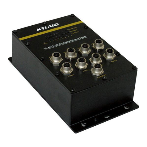
KYLAND KIEN1005 User manual

KIEN1005 Industrial Ethernet Switch
User’s Manual
KYLAND Telecom Technology Co., Ltd.
9/2006


──────────────────────── 1 ────────────────────────
KIEN1005 Industrial Ethernet Switch
User’s Manual
Copyright © 2005 KYLAND Telecom Technology CO., LTD.
All rights reserved.
No part of this documentation may be excerpted, reproduced, translated, annotated or
duplicated, in any form or by any means without the prior written permission of
Kyland Corporation.
Publisher: Kyland Telecom Technology Co., Ltd.
Address: P.O.Box 100096, 085, Beijing, China
Website: http://www.kyland.cn
Postcode: 100096
Customer Service: +86(10)82900770
Fax: +86 (10)82900780
Email: sales@kyland.cn
Version: V2.0 , September, 2006
Code: e2c01060402

──────────────────────── 2 ────────────────────────

──────────────────────── 3 ────────────────────────
Preface
KIEN1005 is a high performance unmanaged industrial Ethernet switch developed by Kyland for
industrial application 。Its high performance switching engine, closed casing design, low
consumption fan less heat removal, over-current, over-voltage and EMC protection for power
supply input terminal, and excellent EMC protection function of Ethernet RJ45 port enable
KIEN1005 to run in a harsh industrial environment and ensure a high reliability to the system。
The
KIEN1005 Industrial Ethernet Switch Uses Manual
mainly introduces the technical principle,
performance index, installation and testing of the KIEN1005 industrial Ethernet switch, and
provides the reference to users to start, expand and maintain the system. Meanwhile, it applies to
the user training and learning for related technical personnel, so it is a practical education material
for mass users to learn about the KIEN1005 industrial Ethernet switch。
Main contents are:
Chapter One: Overview and System Features
Chapter Two: Performance Specification and Service Functions
Chapter Three: Hardware Structure
Chapter Four: Field-testing Methods
Appendix A: Twisted-pair Cable and Pin Assignment Rules
Appendix B: Cable Type and Specifications
Appendix C: Glossary
Statement: For continuous update and perfection of the product and technology,
the contents of this manual may not be consistent with the actual product, please
contact with us about related contents. For the latest information, please visit our
website or contact with our local service representative directly。

──────────────────────── 4 ────────────────────────
Safety Notices
This product can provide excellent and reliable performance within its design scope. However, it
needs to avoid the damage or destroy by human reasons。
Read this Manual thoroughly and keep it well for future reference。
Do not place the equipment next to the source of water and the damp place。
Do not place anything on the power cable. Please place it somewhere that can
not be reached。
In order to avoid fire, do not tie or pack the cable。
The connector of the power supply and other equipment connection should be
connected firmly and regularly checked。
If the situation below occurs, please power off and contact with our company immediately。
1. Water into equipment;
2. Equipment is broken or the crust is cracked;
3. The equipment works abnormally or the performance provided has changed
completely;
4. The equipment gives off odor, smoke or noise。
Pay attention to the cleanness of the fiber socket and jack. When the
equipment operates, do not watch the end-face of the fiber directly。
Pay attention to the cleanness of the equipment and clean it with soft cotton
cloth if necessary。
Do not repair the equipment by yourself unless it is definitely indicated in this
manual。

Industrializing the Ethernet
Simplifying Industrial Communication
──────────────────────── 5 ────────────────────────
Description of Warning Mark:
This manual uses two kinds of obvious warning marks to prompt users that
more attention should be paid during operation。The meanings of these
marks as follows:
Warning: The comment after this mark should be paid more
attention, the incorrect operation will cause the switch to be
damaged seriously or it will cause body injury for the operator。
Caution, Note, Warning and Dangerous: Indicate where more
attention should be paid。

──────────────────────── 6 ────────────────────────
Contents
Chapter One System Overview................................................................................................7
1.1 Overview..........................................................................................................................................7
1.2 Features...........................................................................................................................................7
Chapter Two Performance Specification...................................................................................9
2.1 System Specification......................................................................................................................9
2.2 Service Port Specification...........................................................................................................11
2.3 Service Functions.........................................................................................................................11
Chapter Three Hardware Structure.........................................................................................13
3.1 System Structure..........................................................................................................................13
3.2 Switch Structure............................................................................................................................14
3.2.1Casing....................................................................................................................................14
3.2.2 Front Panel.........................................................................................................................15
Chapter Four Field-testing Methods .......................................................................................20
4.1 Self Testing ...................................................................................................................................20
4.2 Ethernet Port Testing...................................................................................................................20
4.3 Fiber Port Testing.........................................................................................................................21
Appendix A: Twisted-pair Cable and Pin Assignment Rules.....................................................23
Appendix B: Cable Type and Specifications............................................................................27
Appendix C Glossary.............................................................................................................28

──────────────────────── 7 ────────────────────────
ChapterOne System Overview
1.1 Overview
KIEN1005 series contains two models:KEIN1005-5T and KIEN1005-1S(M)
-4T
KIEN1005-5T offers five adaptive TP ports of 10/100BASE-T/TX, which can
be configured to 10BASE-T or 100BASE-TX and half-duplex or full-duplex
mode。KIEN1005-1S(M)-4T provides one full-duplex fiber port of 100Mbit/s
and four TP ports of 10/100BASE-T/TX, which can be configured to
10BASE-T or 100BASE-TX and half-duplex or full-duplex mode. The switch
can be connected by plug-and-play to save start-up time and offers 18-36V
DC power supply input ensuring a high reliability。
1.2 Features
1. High performance industrial Ethernet switch
10/100Base-T/TX adaptive Ethernet ports (full/half-duplex),auto
MDI/MDI-X connection。
100Base-FX full-duplex fiber port, single mode or multimode
Broadcasting storm protection。

──────────────────────── 8 ────────────────────────
2. Industrial power supply
Industrial DC24V(DC18V~36V)input。
Protection against over-current and over-voltage。
Protection against reverse polarity connection.
Electromagnetic compatibility protection, industrial level four.
3. Industrial casing design
Highly-effective fan less heat dissipation, with operation temperature range
of -35℃~+75℃.
Closed aluminum casing, IP40 protection class for harsh industrial
application.
Easy DIN-Rail mounting.

Industrializing the Ethernet
Simplifying Industrial Communication
──────────────────────── 9 ────────────────────────
Chapter Two Performance Specification
2.1 System Specification
The system specification of the KIEN1005 Industrial Ethernet Switch is shown in
Table 2-1。
Table 2-1 System Specifications
Specifications KIEN1005-5T KIEN1005-1S(M)-4T
10/100Base-TX
5 x RJ45 4 RJ45
100Base-FX 1 S(M)
System
Standard: IEEE802.3 、IEEE
802.3x 、IEEE 802.3u 、IEEE
802.1p、IEEE 802.1Q
Store-and-forward switching rate:
148810 pps
Max filter rate: 148810 pps
Switching
mode: store-and-forward
System switching bandwidth: 1.0G
Electromagnetic Interference :
EN55022
Electromagnetic compatibility:
EN50082-2( level four, class A).
Standard: IEEE802.3、IEEE 802.3x、
IEEE 802.3u 、IEEE 802.1p、IEEE
802.1Q
Store-and-forward switching
rate: 148810 pps
Max filter rate: 148810 pps
Switching mode: store-and-forward
System switching bandwidth: 1.0G
Electromagnetic Interference :
EN55022
Electromagnetic
compatibility: EN50082-2( level four,
class A).
TP port
Physical Interface:
RJ-45 socket, shielded
RJ-45
port: 10Base-T/100Base-TX,
auto-negotiation
Interface standard: IEEE802.3
Physical Interface: RJ-45 socket,
shielded
RJ-45 port: 10Base-T/100Base-TX,
auto-negotiation
Interface standard: IEEE802.3
Transmission Distance: <100m

──────────────────────── 10────────────────────────
Transmission Distance: <100m
Fiber port
Optical
power:
>-13dbm(SM) >-20dbm(MM)
Sensitivity:
<-28dbm(SM) <-35dbm(MM)
Wavelength :1310nm(SM)
1550nm(SM) 1310 nm (MM)
Transmission distance: 20~
80Km(SM)
<2Km(MM)
Connector: SC/FC
Transmission rate: 125Mbps
Power supply
Power input: DC24V(DC 18V~
36V)
Power consumption: <6W
Over-current protection: built-in
Power input: DC24V(DC 18V~36V)
Power consumption: <6W
Over-current protection: built-in
Dimensions(W
x H x D)
36.5 x 120 x 90(mm) 36.5 x 120 x 90(mm)
Ambient
conditions
Operating temperature: -35℃~75
℃
Storage temperature: -45℃~85℃
Relative humidity
(non-condensing): 10%~95%
Operating temperature: -35℃~75℃
Storage temperature: -45℃~85℃
Relative humidity (non-condensing):
10%~95%

Industrializing the Ethernet
Simplifying Industrial Communication
──────────────────────── 11────────────────────────
2.2 Service Port Specification
1.10/100Base-T/TX adaptive RJ45 Ethernet ports. Each port is adaptive to
10/100M and full/half-duplex mode. The maximum Transmissions
distance is 100m Max.
2.100Base-FX fiber port, single mode or multimode, Max throughput of each
pair optical fiber is 100Mbps,complies with IEEE802.3/802.3U/802.3X.
3.100Base-FX fiber port, single mode or multimode, throughput of each pair
optical fiber is 100Mbps Max, it is enforced to 100M full-duplex mode and
complies with IEEE802.3/802.3U/802.3X.
4.RJ45 ports indicators: Yellow for rate, ON: 100M; OFF:10M. Green for link
state, ON: valid connection; BLINKING: active network; OFF: no
connection.
2.3 Service Functions
1.LED Indicating
The LEDs indicate the port status correctly including transmission rate, link
status and system status.
2.802.1p Prioritization
KIEN1005 conforms to 802.1p, which is used the most widely in LAN
environment. The end-users of KIEN1005 can make use of this function to

──────────────────────── 12────────────────────────
configure the port-based prioritization when 802.1p is not supported at user’s
end and different priority is necessary for different ports’ services. Only the
data package without Prioritization in the Packet in the ports can be affected
by this function. THE 5th port of KIEN1005 supports 2 levels (high, low)
prioritization.
3.Layer-2 Switching
Switches work in two ways: Cut-Through and Store-and-Forward. In
Cut-Through, a data packet is immediately relayed further after detecting the
target address; in Store-and-Forward, a data packet is first read-in
completely and checked for errors before the switch relays the same.
KIEN1005 employs Store-and-Forward that is a switching mode widely used.
4.Broadcast Storm Control
Broadcast storm is the ceaseless transfer of broadcast frame or multicast
frame in bridge, which is caused by loop and will wastemuch bandwidth. The
purpose of broadcast storm control is to optimize the performance of switch
network. KIEN1005 supports the broadcast storm based on percentage.
With the control percentage, the broadcast flow of KIEN1005 will be
monitored and controlled effectively. The switch will filter out the over flow
and ensure the flow percentage is normal once the bandwidth of broadcast
flow exceed the limit.

Industrializing the Ethernet
Simplifying Industrial Communication
──────────────────────── 13────────────────────────
ChapterThree Hardware Structu re
3.1 System Structure
Figure: 3-1 System structure
The system hardware mainly consists of following parts:
1.The switching network controller adopts the high performance ASIC chip
technology to provide the layer2 line rate forward for the data packet.
2.The optical fiber interface employs the optical receiving and transmitting
integrated module to ensure stable performance.
3.Industrial power supply with protection against over-current and
over-voltage.
4.Protection against reverse polarity connection.
5.Industrial level four Electromagnetic compatibility protection of power
interface.
6.EMC protection of service interface.

──────────────────────── 14────────────────────────
3.2 Switch Structure
3.2.1Casing
Figure: 3-2 KIEN1005-5T

Industrializing the Ethernet
Simplifying Industrial Communication
──────────────────────── 15────────────────────────
Figure: 3-3 KIEN1005-1S(M)-5T
3.2.2 Front Panel
The front panel of KIEN1005-5T has integrated five Ethernet RJ45 ports of
10Base-T/100Base-TX, one power terminal and one indicating light for
power supply. Its structure is shown as Figure:
4
3
2
1
LINK/ACT
10/100M
POW
5
Figure: 3-4 KIEN1005-5T front panel

──────────────────────── 16────────────────────────
The front panel of KIEN1005-1S(M)-4T contains four Ethernet RJ45 ports of
10Base-T/100Base-TX, one pair of fiber ports, one power terminal, one
indicating light for power supply, and one indicating light for fiber port running
status. It is structured as figure:
LINK/ACT
10/100M
1
2
3
4
RX
TX
POW ACT
Figure: 3-5 KIEN1005-1S(M)-4T front panel
Optical fiber interface
KIEN1005-1S(M)-4T offers one full-duplex fiber port of 100Base-FX,
single mode or multimode, which is numbered as five. Its connector can be
SC or FC. The optical fiber interface should be used in pair (TX and RX in
pair), where, the TX interface is the optical transmitting terminal which
connects to the optical receiving terminal RX for the optical interface of the
remote switching, the RX is the optical receiving terminal which connects
to the optical transmitting terminal TX for the same optical interface of the
remote switch..
Ethernet RJ45 Port
KIEN1005-5T offers five Ethernet RJ45 ports of 10Base-T/100Base-TX.
KIEN1005-1S (M)-4T contains four Ethernet RJ45 ports of
10Base-T/100Base-TX. Each RJ45 port is adaptive and supports auto

Industrializing the Ethernet
Simplifying Industrial Communication
──────────────────────── 17────────────────────────
MDI/MDI-X connection. It can be connected by straight-through/cross-over
cable to terminal devices, servers, hubs or other switches. Each port
supports IEEE802.3x, so the optimum transmission mode (half-duplex or
full-duplex) and data rate (10 Mbps or 100Mbps) will be selected
automatically (the connected devices should supports this features too). If
the connected devices are not adaptive, the port will send at the correct
rate but with default mode of half-duplex.
Power Input Terminal
The KIEN1005 uses the DC24V power supply. It uses the 3.81 ㎜gap
3-wire phoenix terminal to connect to the power supply. The diameter of
the power supply is less than 1.5 ㎜.
The sequence of the connection is shown in Figureure.3-6. The connection
wire and the installation step as follows:
Peel off the crust of the power cable for about 5mm to twist several of
exposed copper wires into one bundle;
1.Use the 2.5mm “-“ shape screw driver to loose the “power cable lock
screw, insert the power cable into the hole at the end of the terminal,
screw tightly the “power cable lock screw”;
2.Insert the power supply terminal into the DC socket of the equipment,
use the 2.5mm “-“ shape screwdriver to screw tightly two “terminal lock
screw” to fixedly connect the terminal and the power supply connector.

──────────────────────── 18────────────────────────
Power Gr ound
+24V
Pr ot ect i on Gr ound
Ter mi nal Locki ng Scr ews
Locki ng Scr ews f or Power
Cabl es
Figure: 3-6 Connection Diagram of DC Power Supply Terminal
LED Indicator
The LED indication light of the KIEN1005 front panel can display the status
of the system operation and the port, which make it easy to find problem
and troubleshooting. Table 3-1 describes the meanings of the front panel
LED indication light.
Table 3-1 Description of LED Indication Light
LED Condition Status
System Status LED
ON The power supply is in connection and runs
normally.
POWER
OFF The power supply is not connected or runs
abnormally.
Fiber Port LED
ON Valid connection in port
BLINKIN
G Network activity in port
LINK/ACT
OFF No valid connection in port
Ethernet RJ45 Port Status LED
There are two indicating lights for each RJ45 port, yellow is for port rate
and green for link status.
Table of contents
Other KYLAND Network Router manuals
Popular Network Router manuals by other brands

Cabletron Systems
Cabletron Systems MMAC-Plus 9F106-01 user guide

Ruijie
Ruijie Reyee RG-EG105GWT Hardware installation and reference guide

Draytek
Draytek Vigor2920 Series user guide

H3C
H3C S5830V2 series Security configuration guide

Brocade Communications Systems
Brocade Communications Systems MLX Series installation guide

TP-Link
TP-Link TL-WA850RE Quick installation guide