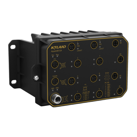
KYLAND KIEN8000 User manual

KIEN8000 Industrial Ethernet Switch
User’s Manual
KYLAND Telecom Technolo y Co., Ltd.

KIEN8000 Industrial Ethernet Switch
User’s Manual
Copyri ht © 2005 KYLAND Telecom Technolo y CO., LTD.
All ri hts reserved.
No part of this documentation may be excerpted, reproduced, translated, annotated or
duplicated, in any form or by any means without the prior written permission of KYLAND
Corporation.
Publisher: KYLAND Telecom Technology Co., Ltd.
Address:5/F, Office Building, Tr nsport Center, E st of Xis nqi Bridge
H idi n District, Beijing, Chin (100089)
Website: www.kyl nd.cn
Tel: +86 –10-82900770
F x: +86 –10-82900780
E-m ils les@kyl nd.cn
VersionV1, Oct, 2005
No.e8 01051001

Preface
KIEN8000 is PoE-en bled PSE Power Source Equipment industri l Ethernet
switch with IP67 protection cl ss speci lly designed for industri l pplic tions. Its
high-perform nce switching engine, rugged ch ssis, ribbed f nless he t dissip tion
c sing, protection g inst over-current, over-volt ge nd EMC protection en ble it to
work well in h rsh environment.
The User’s Manual for KIEN8000 Industrial Ethernet Switches m inly introduces
technologic l theory, perform nce indexes, mounting nd testing of KIEN8000
industri l Ethernet switches for user’s reference on system opening, exp nsion nd
routine m inten nce. It is lso pplic ble to tr ining to users nd study of rel ted
technici ns. It is pr ctic l book for users to know nd underst nd KIEN8000
industri l Ethernet switches.
This document m inly cont ins following contents:
Ch pter1 Overview nd System Fe tures
Ch pter2 Perform nce Specific tions nd Service Functions
Ch pter3 H rdw re Structure
Ch pter4 Inst ll tion & Mounting
Ch pter5 Testing Method
Ch pter6 Networking Modes nd System Configur tion
Appendix A Twisted-p ir nd Pin Distribution Rules
Appendix B Gloss ry
Statement: For continuous update and perfection of the product and technolo y,
the contents of this material may not be consistent with the actual product, please
contact with us about related contents. If it is necessary for you to query the latest
information on the product, please query our cooperation Website or contact with
your local service representative directly.

Safety Notices
This product c n provide excellent nd reli ble perform nce within its design scope.
However, it needs to void the d m ge or destroy by hum n re sons.
Re d this M nu l thoroughly nd keep it well for future reference.
Do not pl ce the equipment next to the source of w ter nd the d mp pl ce.
Do not pl ce nything on the power c ble. Ple se pl ce it somewhere th t c n not
be re ched.
In order to void fire, do not tie or p ck the c ble.
The connector of the power supply nd other equipment connection should be
connected firmly nd regul rly checked.
Under following conditions, ple se power off nd cont ct with our comp ny
immedi tely.
1. W ter into equipment;
2. Equipment is broken or the crust is cr cked.
3. The equipment works bnorm lly or the perform nce provided h s ch nged
completely.
4. The equipment gives off odor, smoke or noise.
P y ttention to the cle nness of the equipment nd cle n it with soft cotton cloth
if necess ry.
Do not rep ir the equipment by yourself unless it is definitely indic ted in this
m nu l.

Description of W rning M rk:
This m nu l uses two kinds of obvious w rning m rks to prompt users th t more
ttention should be p id during oper tion. The me nings of these m rks s follows:
W rning: The comment fter this m rk should be p id more ttention, the
incorrect oper tion will c use the switch to be d m ged seriously or it will
c use body injury for the oper tor.
C ution, Note, W rning nd D ngerous: Prompt where more ttention
should be p id.


CONTENTS
Chapter 1: System Overview ......................................................................................................................... 1
1.1 Product Overview ................................................................................................................................... 1
1.2 System Fe tures ...................................................................................................................................... 1
1.3 P cking List nd Unp cking Check ....................................................................................................... 2
Section 2: Performance Specifications .......................................................................................................... 4
1.4 System Specific tions ............................................................................................................................. 4
1.5 Service Interf ce ..................................................................................................................................... 5
1.6 Service Functions ................................................................................................................................... 5
Section 3: Hardware Structure ..................................................................................................................... 5
1.7 System Structure ..................................................................................................................................... 5
1.8 Switch Structure ..................................................................................................................................... 5
1.8.1 Ch ssis .................................................................................................................................. 5
1.8.2 Front P nel ........................................................................................................................... 6
1.8.3 RJ45 Ethernet Port ............................................................................................................. 10
1.8.4 M12 Ethernet Port .............................................................................................................. 13
Section 4 :Hardware Mountin ................................................................................................................... 15
1.9 Inst ll tion Requirements ..................................................................................................................... 15
1.10 M in Unit Inst ll tion ........................................................................................................................ 15
1.10.1 DIN-R il Mounting .......................................................................................................... 15
1.10.2 W ll Mounting .................................................................................................................. 17
1.11 Connecting C ble ............................................................................................................................... 20
1.12 C bles Wiring ..................................................................................................................................... 21
Section 5: Testin Methods ........................................................................................................................... 22
1.13 Self-Check .......................................................................................................................................... 22
1.14 Testing Ethernet Ports ......................................................................................................................... 22
Chapter 2:Networkin Modes and System Confi uration ....................................................................... 24
1.15 Networking ......................................................................................................................................... 24
-I-

Chapter 1: System
Overview
Product Overview
KIEN8000 is PoE-en bled PSE Power Source Equipment industri l Ethernet
switch with IP67 protection cl ss speci lly designed for industri l pplic tions. Its
high-perform nce switching engine, rugged ch ssis, ribbed f nless he t dissip tion
c sing, protection g inst over-current, over-volt ge nd EMC protection en ble it to
work well in h rsh environment.
KIEN8000 comes with lumnimum-m de ch ssis of IP67 protection cl ss. All its
interf ce components re with IP67 protection. It offers two types of interf ces: RJ45
nd M12 respectively for KIEN8000-RJ45(P) nd KIEN8000-M12(P). It c n be
inst lled in two w ys: DIN-R il nd W ll-mounting. KIEN8000 offers 8 ports 10B se-
T/100B se-TX(power sourcing or not). The power sourcing ports c n provide power
supply of DC24V to remote Ethernet devices or powered devices (PD for short) t
m x current of 300MA. E ch Ethernet port of KIEN8000-RJ45(P) is d ptive to
10B se-T or 100B se-TX, e, it c n lso do uto MDI/MDI-X connection. E ch
Ethernet port of KIEN8000-M12(P) is fixed t 10B se-T nd d ptive to h lf-duplex or
full-duplex mode, it c n be uto MDI/MDI-X connected too.
System Features
1. Hi h-performance Industrial Ethernet Switch
10/100B se-T/TX Ethernet ports, d ptive, full/h lf duplex, Auto MDI/MDI-X
connection.
Ethernet port c n be power sourcing; sourcing-volt ge: DC24V; sourcing-current:
300mA m x.
Bro dc sting storm Protection
Store- nd-forw rd switching mode conforms to IEEE802.3/802.U/802.3X.
Tr nsp rent tr nsmission of VLAN t g p cket
1

KIEN8000 User M nu l
2. Industrial Power
Industri l power input of DC24VDC18V36V.
Reli ble protection for EMC nd g inst over-current/over-volt ge.
3. Ru ed Desi n
Ribbed he t-remov l design (f nless); oper tion t -35° to +75°.
Solid IP67 housing.
E sy DIN-R il mounting or option l w ll-mounting.
Packin List and Unpackin Check
1. Packin List
The p cking box includes the following:
KIEN8000 1
M12 power termin l 1
M12 Ethernet termin l IP67 ccessories for KIEN8000-M12(P) 8
RJ45 Ethernet termin l IP67 ccessories for KIEN8000-RJ45(P) 8
User’s M nu l of KIEN8000 Industri l Ethernet Switches 1
Customer Service Guide 1
Ф3 grounded cold pressure termin l nd M3×8 grounded screw 1
2. Unpackin Check
Before unp cking, pl ce the box on level floor. Note direction of the p cking box
nd ensure its f ce upw rd to prevent dropping of the switch fter unp cking. If you
use h rd object to prize the box, do not m ke this h rd object go into the box too
f r to prevent d m ges to the switch.
After unp cking, count the switch, including the m in unit, ccessories, user’s
m nu l, customer service guide, etc, in ccord nce with the p cking list. Check
their ppe r nce qu lity.
2

Kyland Telecom
W rning
The switch cont ins fine components. Ple se h ndle it softly nd void
intense vibr tion lest switch perform nce is ffected.
3

Section 2:
Performance
Specifications
System Specifications
The system specific tions of KIEN8000 industri l Ethernet switch is shown s t ble
2-1.
T ble 2-1 System Specific tions
Specs Description
Port Type nd Qu ntity 8 ×10B se-T/100B se-TX
System Perform nce
St nd rd: IEEE802.3IEEE 802.3xIEEE 802.3u
Stor ge nd forw rd r te: 148810 pps
M ximum filtering r te: 148810 pps
Switch method: Store nd forw rd
System switching b ndwidth: 4.8G
EMC: EN55022; EN50082-2
Ethernet Port
Physic l interf ce: RJ-45(shielded) or M12 socket, IP67
RJ-45: 10/100B se-T/TX, uto-negoti t ble
St nd rd: IEEE802.3
Tr nsmission Dist nce: <100m
Sourcing Volt ge: DC24V
Sourcing Current: M x 300mA
Power Supply
Power interf ce: M12 t IP67 protection cl ss
Power supply: DC24VDC 18V36V
Consumption: <64W
Over-current protection: Built-in
Mech nic l P r meters
DimensionH×W×D: 21512066
Inst ll tion: DIN-R il or W ll-mounting
He t remov l: Ribbed luminum c sing without f n
Outlet: Service in front or side, power supply in front
Protection cl ss: IP67
Weight: 2
Ambient Conditions
Oper tion temper ture:-3575
Stor ge temper ture: -4585
Humidity: 10%100% (non-condensing)
4

Kyland Telecom
Service Interface
18 Ethernet ports 10B se-T/100B se-T, e ch is d tpive to 10M or 100M nd h lf-
duplex or full-duplex mode. AutoMDI/MDI-X connection is supported. The
tr nsmission dist nce is less th n 100m.
2The Ethernet port is bleo to source DC24V power supply with m x 300MA
current.
3Conform to IEEE802.3/802.3U/802.3X.
Service Functions
KIEN8000 offers such service functions s following:
1LED Indicator
The LEDs of the front p nel indic te the port st tus correctly including tr nsmission
r te, link st tus nd system st tus.
2Layer-2 Switchin
Switches work in two w ys: Cut-Through nd Store- nd-Forw rd. In Cut-Through,
d t p cket is immedi tely rel yed further fter detecting the t rget ddress; in Store-
nd-Forw rd, d t p cket is first re d-in completely nd checked for errors before
the switch rel ys the s me. KIEN1000-PSE employs Store- nd-Forw rd th t is
switching mode widely used.
3Power Sourcin
E ch Ethernet port supplies DC24V volt ge nd up to 300mA current to remote
Ethernet instruments or PoE Powered Devices (PD).
5


Section 3: Hardware
Structure
System Structure
KIEN8000 h rdw re is structured s Figure3-1:
! "# $% & "'
$" % $( ( #%
)$%
)$#%
*+,,( -
)$#%
" #% . / #
)$% )$% )$% )$% )$% )$% )$% 0
Figure 3-1 H rdw re Structure
System h rdw re m inly consist the following p rts:
1 Switching network controller employs ASIC chip technology, offering
l yer-2 wire-speed tr nsfer of d t p ckets.
2 Industri l isol ted power supply with protection of over-current, over-volt ge
nd EMC.
3 EMC protection for ll Ethernet ports.
0Switch Structure
0Chassis
The ch ssis of KIEN8000 is structured for w ll mounting or DIN r il mounting. The
switch is covered completely for six sides to re ch IP67 protection cl ss. The
luminum-m de ch ssis is one p rt of the he t dissip tion system. The he t gener ted
5

KIEN8000 User Manual
by system is dissip ted by using the single-rib sh pe he t dispersion in r di tion nd
convection m nners with high efficiency, gre tly improving high temper ture
perform nce. It disc rds the tr dition l xi l flow f n nd reduces tot l power
consumption but incre ses system st bility. The ch ssis of KIEN8000 is shown in the
Figure 3-2:
Dimensions14255.4120.5H×W×D:21512066
. KIEN8000-RJ45(P) b. KIEN8000-M12(P)
Figure 3-2 KIEN8000
W rning:
The shell of this switch is p rt of the whole equipment he t dissip tion system. It will
get hot bec use of he t dissip tion when the equipment works norm lly, do not touch
the crust when the equipment works to prevent from sc lding.
0Front Panel
The front p nel of KIEN8000 integr tes 8 LED running indic tors of service interf ces
6

nd system indic tors s well s power input M12 termin l. For KIEN8000-RJ45(P),
the 8 M12 Ethernet ports re lso fixed in the front p nel. The 8 RJ45 Ethernet ports
re in the side of the ch ssis of KIEN8000-RJ45(P). Its structure is showed in the
Figure 3-3:
. KIEN8000-RJ45(P) b. KIEN8000-M12(P)
Figure 3-3 Front P nel
LED Indicators
Indic tors on the front p nel of KIEN8000 show the st tus of system oper tion
nd ports to find nd correct f ults. The T ble 3-1 shows the me nings of these
LED indic tors in the front p nel.
7

KIEN8000 User Manual
T ble 3-1 LED Indic tor Description
LED Conditions Status
System Status LED
RUN ON Running norm lly
OFF Running bnorm lly
Ethernet Port Status LED
POWER
OUT
ON Power is being sourced
OFF No power sourcing
10M/100M On 100M running st tus (i.e., 100B se-TX)
Off 10M running st tus (i.e., 10B se-T)
LINK/ACT
On Ports h ve effective network connection
Blink Ports h ve network ctivity.
Off Ports h ve no effective network connection.
)$#%1$""# $%2
The power termin l of KIEN8000 is M12 of IP67 protection cl ss. Its ppe r nce
is shown in Figure 3-4:
Figure 3-4 M12 Power Connector
M12 power termin l h s five pins for input of DC24V, the pins re positioned s
figure 3-5.
8

Figure 3-5 PIN Position
Dis ssemble the c ble plug of M12 termin l s shown in Figure 3-6:
He d
Sleeve
Comp ction ring
Termin l
Screw
Airproof ring
Comp ction screw
Figure 3-6 M12 Termin l Plug
Grouding Protection
There re tre d hole t the bottom p nel of KIEN8000 nd Ф3 grounded cold
pressure termin l nd M3×8 grounded screw enclosed with the switch. As shown
in Figure 3-7, connect one end of grounding c ble with the cold pressure termin l
nd fix it on the grounding hole of swtich by screw. The other end of grounding
c ble c n be connected to ground. The di gr m of grounding c ble is less th n
2mm.
M12 Power Termin l Pin Definition
3pin 1 TX+ 4Sourcing DC24V
+
3pin 3 TX- 4
Sourcing DC24V
+
9

KIEN8000 User Manual
Picture3-7 KIEN8000 Grounding Method
0RJ45 Ethernet Port
KIEN8000-RJ45(P) offers 8 RJ45 IP67 ports of 10B se-T/100B se-TX which
m y be power sourcing or not. E ch port is d ptive nd support for uto
MDI/MDI-X connection. The switch c n be connected to termin l device or other
switches by str ight-through or cross-over c bles. E ch port c n um tic lly
select h lf-duplex or full-duplex nd correct port r te (10 Mbpso or 100Mbps)
when the connected devices support for such fe ture. If the fe ture is not
v il ble to the connected devices, the correct r te will be set up nd h lf-duplex
will be selected def ult.
10
Table of contents
Other KYLAND Network Router manuals