Brite View BV-254 User manual

BV-210/BV-254
User Manual
¾200 Mbps
¾1.1” Slimmest Design
¾Low Power Consumption
¾Best Performance
Powerline Ethernet Bridge
Powerline Ethernet Switch
V. 1.0.1
Powerline
Ethernet
Bridge +
S
wi
tc
h

1
TABLE OF CONTENT
ORDERING INFORMATION.....................................................................................................2
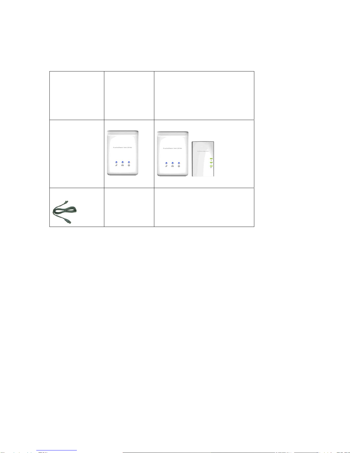
INCLUDED ITEMS.................................................................................................................4
IMPORTANT SAFETY INSTRUCTIONS......................................................................................5
THE FIRST THING YOUT NEED TO KNOW BEFORE INSTALLATION...............................................6
AC outlets connection...........................................................................................................6
Connecting the Powerline Adapter to an Extention Cord............................................8
Electrical Interference............................................................................................................8
Electrical Wiring......................................................................................................................8
PRODUCT OUTLOOK ...........................................................................................................9
PRODUCT OVERVIEW ........................................................................................................11
Standby Mode ........................................................................................................................11
PRODUCT INSTALLATION ...................................................................................................12
Setting Logical Network Group.........................................................................................12
Remove a Device from a Logical Network Group........................................................13
Setting Up a Different Network Group.............................................................................13
Application 1 – Local Powerline Network Among Computers..................................13
Application 2 – Computer to DSL/Cable Router Connection....................................15
Application 3 – Wireless Access Point Range Extensions........................................17
Business Installation............................................................................................................18
SPECIFICATIONS...............................................................................................................19
FAQ (FREQUENTLY ASKED QUESTIONS)............................................................................20
TROUBLE SHOOTING .........................................................................................................23

2
ORDERING INFORMATION
This BV-210/BV-254 User Manual describes how the powerline connects to the
Ethernet Bridge (BV-210) and to the Ethernet Switch (BV-254).
The BV-210 is a one-port Powerline Ethernet Bridge. The BV-254 is a four-port
Powerline Ethernet Switch.
Powerline technology lets you use your home's electrical system to transmit data signals,
and it uses the electrical system as a network, with each electrical outlet serving as a node.
Any Ethernet-equipped device (PCs, TiVos, and set-top boxes, among others) that's
connected to a power line adapter can be part of the power line network.
After successful installation, the BV-210 and BV-254 Powerline network behaves like a
traditional LAN for computers. These brite-View Powerline Adapters support up to 200Mbps
network speed.
See the following table for a summary.
Categories Description
Powerline Ethernet Bridge
(BV-210)
The BV-210 is a HomePlug device used to extend
a LAN into a separate room using the existing
electrical system in the building. An Ethernet cable
from the network router is plugged into a bridge,
which plugs into an AC wall outlet.

3
Powerline Ethernet Switch
(BV-254)
The BV-254 Powerline 4-Port 200Mbps Ethernet
Adapter turns any power outlet into a 4-port home
network connection. The BV-254 adapter extends
your network to provide 200Mpbs connections
without the cost or hassle of running new wiring.
Just plug the BV-254 Powerline 4-Port Ethernet
Adapter directly into the wall outlet, and you are
ready.
*You will need at least a pair of brite-View powerline Ethernet Adapters in order to enable powerline
communication.

4
INCLUDED ITEMS
POWERLINE
ETHERNET
SWITCH
DUAL PACKAGE
POWERLINE ETHERNET SWITCH
+POWERLINE ETHERNET BRIDGE
COMBO PACKAGE
DEVICE
Two devices
X 2
Combinational devices
ETHERNET CABLE
2

5
NOTICE:This product complies with IC: ICES-006; en conformité avec IC: NMB-006
IMPORTANT SAFETY INSTRUCTIONS
This product is intended for connection to the AC power line. For installation instructions,
refer to the Installation section. The following precautions should be taken when using this
product.
zPlease read all instructions before installing and operating this product.
zPlease keep all instructions for later reference.
zPlease follow all warnings and instructions marked on the product.
zFor safety reasons, when the device is powered on, the venting holes should
remain uncovered.
zUnplug the Powerline device from the wall outlet before cleaning. Use a dry cloth
for cleaning. DO NOT use liquid cleaners or aerosol cleaners.
zDO NOT operate this product near any liquid.
zThis product should never be placed near or over a radiator and heat register.
This product relies on the building’s electrical installation for short-circuit (over-current)
protection.
zIt is recommended that the adapter is plugged directly into an electrical outlet, rather
than into an uninterruptable power supply or extension cord with surge protection.
brite-View Powerline adapters have their own power filter for surge protection.
zOnly a qualified technician should service this product. Opening or removing covers
may expose you to dangerous voltage or other hazards.
Unplug the product from the wall outlet and refer the product to qualified service personnel
for the following conditions:
¾If liquid has been spilled into the product.
¾If the product has been exposed to rain or water.
¾If the product does not operate normally when the operating instructions are
followed.
¾If the product exhibits a distinct change in performance.

6
The FIRST THING YOUT NEED TO KNOW BEFORE INSTALLATION
These powerline adapters sends data to and from each other over the existing electrical
wiring in your home, and the network performance may be affected by electrical noises or
the length of the electrical wiring in your house. Keep the following in mind when placing
this powerline device at home.
AC outlets connection
Avoid connecting these adapters to an uninterruptible power supply (UPS) or backup power
supply device. For best results, we recommend connecting the adaptors directly to a wall
outlet. Avoid connecting high power-consumption appliances to the same wall outlet. Plug
these power consuming devices onto a noise filtering extension cord to prevent
interference on the powerline network. See the following illustration for details:
For best performance, isolating the powerline adapter from other appliances is
recommended.

7
The following connections are NOT recommended, although current powerline
communication technology can overcome most noise interference from other AC adapters
or chargers.

8
Connecting the Powerline Adapter to an Extention Cord
If you must connect this device to a power strip, please keep the following suggestions in
mind:
• Make sure the extension cord does not have a noise filter or a surge protector, as these
features decrease the network signal strength over the electrical wiring.
• Use an extension cord as short as possible.
• Do not connect the powerline adaptor to an extension cord that receives power from
another extension cord.
Electrical Interference
Certain electrical devices emit electrical noise. The noise may interfere with the
performance, speed, and reliability of the powerline adapters. For best results, we
recommend connecting an electrical noise filter to noise emitting appliances.
The following appliances are more likely to produce electrical noise:
•Battery chargers (including cell phone chargers)
•Hair dryers
•Power drills
•Halogen lights
•Vacuum cleaners
Additionally, the powerline adapters may interfere with the following appliance:
•Lights or lamps which have a touch-sensitive on/off feature
Electrical Wiring
This device sends data to and from each other over the existing electrical wiring in your
house. If two wall outlets are separated by a great distance of electrical wiring, these
devices may not communicate well with each other. For more information, refer to the
troubleshooting section.

9
PRODUCT OUTLOOK
A. Top View
Powerline Ethernet Bridge Powerline Ethernet Switch
B. Side View
Ethernet Po
r
t B
A
C
E
V
ent Holes
(Do not block)
Four Ethernet Ports
D
A C
E
V
ent Holes
(Do not block)

10
*1 : The “PLC Link/ACT “ LED indicator will turn on when the powerline link is detected. If the device is serving as a
station, the LED indicator will flash to indicate powerline activity. If the device is serving as a CCo (Central
Coordinator), the LED indicator will a solid light, even in the presence of powerline activity.
Item Item Name Description
A PLC Link/ACT LED
On: Powerline link detected (*1)
Blinking:
(1) Powerline traffic detected (*1)
(2) Powerline device not in any logical network.
Off: No powerline traffic detected
BEthernet Link/ACT LED
On: Ethernet link detected
Blinking: Ethernet traffic detected
Off: no Ethernet link detected
CPOWER LED
On: powered on
Blinking:
(1) Rebooting or
(2) The device is sitting at a network node
for interfacing with another network
Off: powered off
DHomePlug 1.0 DET LED Blinking: HomePlug 1.0 Traffic detected
Off: HomePlug traffic 1.0 not detected
EGROUP Button
Press for 2 seconds to allow a device to
interface with a logical network or clear
grouping information
FReset-to-factory-default Button Press to reset firmware setting to factory default

11
PRODUCT OVERVIEW
These powerline Ethernet adapters are virtually Ethernet cable and Ethernet hub
replacement. Two of these powerline Ethernet bridges (or one bridge and one switch) can
be used to replace an Ethernet cable, for connecting any computer to another computer,
computer to a DSL/cable router, or a wireless AP to a DSL/cable device. Many pairs of this
devices can be connected together to form a network communication. For example, three
computers can be connected to a DSL/cable router for internet access via four of these
powerline Ethernet adapters, each computer is connected to one powerline adapter and the
DSL/cable router to the fourth powerline adapter.
The maximum amount of nodes in a powerline logical network group is defined in the
SPECIFICATIONS section in this user’s manual.
If a user finds two newly purchased devices are not able to communicate with each other,
please press the “reset-to-factory-default” button while the device is plugged into the
electrical socket and powered. If these devices are still not working, please read the other
sections in this user manual for frequently asked questions and trouble shooting.
Standby Mode
If no Ethernet cable is connected to the Powerline Ethernet Bridge within two minutes
after powering it on, this device will go into standby mode automatically, in order to lower
power consumption. Meanwhile, the POWER LED will blink ON and OFF at a slow rate. To
exit the standby mode, insert the Ethernet cable or re-plug in this device to the electrical
outlet.
Note:
1. Some computers support “Wake on LAN” and it may cause the Ethernet adapters to stay
on without entering the standby mode.
2. Powerline Ethernet Switch does not go into standby mode.

12
PRODUCT INSTALLATION
Setting Logical Network Group
Users can set HomePlug AV devices into one or many logical network groups. Devices in
the same logical network group will communicate with each other. Devices in different
network group won’t communicate with each others.
If you have a pair of powerline Ethernet adapters, either one in the pair can be “device A” or
“device B”.
To make powerline device B join device A’s logical network, please do the following steps:
(NOTE: for configuration convenience, please place device A and B together when setting
up the network. After the configuration these devices can be deployed anywhere in the
house.)
Step 1. Clear device B’s logical network group by pressing its GROUP button for 10
seconds. After release the button, all LED lights will simultaneously blink on
and off. It means the network group clearing procedure has started.
The following steps are to be followed in order for device B to interface with device A‘s
logical network:
Step 2. Now press the GROUP button on device A for 2 to 3 sec (make sure POWER
LED starts to blink).
Step 3. After following the previous steps, in less than two minutes, press GROUP
button on device B again, for 2 to 3 seconds (make sure POWER LED starts to
blink). After 10 seconds, device B will start communicating with device A.
Now device A and B can interface with each other. Users can include device C (3rd
Powerline Ethernet adapter) to device A’s logical network by following the same procedures
above. Users can assign as many Powerline devices into this logical network group as
possible until the maximum number of adapters described in the SPECIFICATION section is
reached.

13
Remove a Device from a Logical Network Group
If device A and B are in the same logical network group but you want to remove device A
from this logical network group, just follow the procedure in Step 1 by pressing the GROUP
button on device A for 10 seconds. This will stop the communication between A and B. If
you want to remove a device from a logical network group of 3 or more devices, just press
the GROUP button on that device as explainted in Step 1.
Setting Up a Different Network Group
When you press the GROUP button on device A for 10 seconds, a random network key is
generated and which is different from device A’s network name (clearing device A from its
original network group). You can then add other devices to device AB’s network group by
following Step 2 and Step 3, which will form two groups of logical network in total, using 4
devices.
The following are some application examples and their installations.
Application 1 – Local Powerline Network Among Computers
Connect computers in different rooms with brite-View Powerline Ethernet adapters!
Installation Options:
You need at least 2 brite-View powerline Ethernet bridges in order to establish a network
communication. For example, you can establish a network for computers in different rooms
as shown in Room A and Room B. You can then add more adapters to that network, one by
one.
You can also purchase one powerline Ethernet bridge (one-port) with and a Ethernet switch
(4-port). As shown in Room C, multiple network devices are connect to the Powerline
Ethernet switch, and the laptop computer is connected to the Powerline Ethernet bridge
in Room D.

14

15
Application 2 – Computer to DSL/Cable Router Connection
Use brite-View powerline to establish communication between your computer and your
router – even if they are in different rooms.
Installation Options:
Connect the computer to a brite-View powerline Ethernet bridge as shown in Room A. The
other brite-View powerline Ethernet bridge can be placed in another room, connected to a
broadband DSL/cable router shown in Room B. The picture of Room C shows multiple
network devices connected to a brite-View powerline Ethernet switch, and then linked to the
DSL/cable router in Room D via a single-port powerline Ethernet bridge.

16
Note: Under decent powerline signal conditions, two devices can communicate with each
other without problems even though the two rooms are not right next to each other. (See
the FAQ section for more details.)

17
Application 3 – Wireless Access Point Range Extensions
Use brite-View powerline Ethernet adapters to extend your WiFi network and eliminate WiFi
dead zone.
Installation procedure:
Connect one powerline Ethernet bridge to a wireless access point as shown in Room A.
Then, connect the second included powerline Ethernet bridge or switch to a broadband
DSL/cable router as shown in Room B.

18
Business Installation
We DO NOT recommend these powerline devices for business operation due to the
complexity of the network environment in business settings, although some businesses will
find it an inexpensive networking solution.

19
SPECIFICATIONS
Items Description
Powerline Ethernet Bridge device Powerline Ethernet Switch device
PHY Rate 200Mbps
Effect Data Rate TCP: Up to 90 Mbps
UDP: Up to 91 Mbps TCP: Up to 91 Mbps
UDP: Up to 92 Mbps
Frequency Band 2~28 MHz (With Mask)
Access Methods CSMA/CA channel-access schemes
Qos Four-level priority based contention access, and multi segment bursting
8-level VLAN priority field, TOS field
QoS Classification by destination MAC address and IP Port
Modulation OFDM (QAM 8/16/64/256/1024, QPSK, BPSK, ROBO)
10/100 RJ-45 port 1 port 4 ports
Distance AC Wire : 100 meters
LAN Standards IEEE 802.3, IEEE 802.3U,
PLC Standard HomePlug AV
Operating System OS independent
Max. devices in a
network Group
Up to 63 slaves with 1 master, 64 total devices
IGMP Support for IPv4/IGMP v1,v2,v3 snooping
Support for IPv6 and MLD v1,v2 snooping
Max 16 source addresses and Group Members
Encryption 128-bit AES Link Encryption with key management
LEDs 1. Power (green), 2. Powerline
Activity (green), 3. Ethernet
Link/Activity (green)
1. Power (blue), 2. Powerline Activity
(blue), 3. AV/1.0 DET (blue),
Temperature 0~40 ℃ (Operating); -20~60 ℃ (Storage)
10~85% Non-Condensing (Operating)
Relative Humidity
5~90% Non-Condensing (Storage)
Power Source 100 ~ 240 VAC 50/60Hz
Full load: (110 VAC) = 4.2W; (220 VAC) =
5.3W; (240 VAC) = 5.8W
Power
consumption
Full load: (110 VAC) = 2.7W; (220
VAC) = 3.28W; (240 VAC) = 4W
Standby mode: (110 VAC) = 0.72W;
(220 VAC) = 1.36W; (240 VAC) =
1.4W
NA
Certification CE, CE-LVD, FCC Class B
Table of contents