Kyoeisha Baroness HMA1560 User manual

HAMMER KNIFE MOWER
Before using the machine please ensure that
you have read this manual and the operating
and instruction manual for the engine.
"Required Reading"
Owner's Handling Manual & Parts Catalogue 2005.2

CAUTION
WARNING
CAUTION
WARNING
Warning for Safety
Location of labels
1. Precautions as to use
2. Safety operation
3. Part names
4. Features
5. Specifications
6. Inspection before use
6-1. Lubrication to each part
6-2. Inspection of hydraulic oil
6-3. Hydraulic oil change
6-4. Lubrication of friction surface of each part
7. Tightening each part
8. Engine starting sequence
8-1. Engine start
8-2. Engine start/operation method
8-3. Engine stop method
8-4. Precautions to take when leaving the machine
9. Machine operation
9-1. Machine operation
9-2. Knife clutch
9-3. Traveling lever
9-4. Mowing height adjustment
9-5. Working speed
9-6. Step (simple riding unit)
9-7. Transportation on public road
9-8. Alarm buzzer
9-9. Side brake
10. Hammer knife
10-1. Use of both sides of hammer knife
10-2. Replacement of hammer knife
10-3. Grinding the hammer knife
11. Operation on slope
11-1. Operation on slope
11-2. Precautions as to Operation on a steep slope
12. Precautions as to maintenance
12-1. Precautions as to maintenance
12-2. Prevention of damage due to high-pressure oil
12-3. Precautions as to fuel handling
12-4. Precautions as to battery handling
13. Maintenance schedule
14. Belt adjustment
14-1. Knife
14-2. Hydraulic pump
15. Crawler
15-1. Crawler tension
15-2. Installation/removal of crawler
15-3. Prevention of crawler tearing loose
15-4. Greasing the crawler
16. Adjustment of traveling section
16-1. Adjustment of neutral position of piston pump
16-2. Adjustment of neutral position of traveling lever
16-3. Confirmation after adjustment
17. Engine
18. Hoisting
19. Attaching/detaching the mower portion
20. Gear oil change for traveling motor
21. Wiring diagram
22. Hydraulic circuit
Parts Catalogue
1
2
4
5
6
6
7
7
7
7
7
8
9
9
9
9
9
9
10
10
10
10
10
10
11
11
11
11
11
11
11
11
11
11
12
12
12
12
12
12
13
13
13
13
14
14
14
14
14
14
15
15
16
16
16
17
17
18
19
20
DANGER
CAUTION
CAUTION
CAUTION
CAUTION
CAUTION
CAUTION
CAUTION
WARNING
WARNING
DANGER
WARNING
CAUTION
WARNING
WARNING
CAUTION
CAUTION
CAUTION
CAUTION
CAUTION
CAUTION
CAUTION
CAUTION
CAUTION
DANGER
DANGER

Warning for Safety
Warning labels with the mark have been attached to this machine. The labels indicate the items
which are particularly important from the safety point of view, so please work safety and always
obey warnings.
Warning Marks
Negligence of the warning will cause death or
serious injury.
Negligence of the warning may cause death or
serious injury.
Negligence of the warning may cause injury and /
or physical damage.
Thank you very much for purchasing the BARONESS HAMMER KNIFE MOWER
HMA1560/HMA1720.
This handling manual explains the method of correct use, adjustment and inspection of the
HAMMER KNIFE MOWER. Carefully read this manual before operation so as to thoroughly
understand the machine. The machine is shipped after sufficient trial operation and inspection
when it is completed at the factory. However, whether or not the machine can exhibit its expected
performance depends greatly on the handling method, as well as the skill of inspection,
adjustment, and lubrication before and after operation. Carefully maintain your machine to bring
out the best in the machine and for safe operation. Keep this manual near the machine for future
reference to confirm unclear points as necessary.
Greeting
The type of the machine may change sequentially. Please inform us of the machine No. when
making an inquiry.
For improvement the contents of this manual are subject to change without notice.
Warning marks have been used in this Manual and machine to ensure that you can
operate it safely. Please read carefully to understand well.
Thoroughly understand the operation procedure and safety cautions before you operate
this machine.
The marks and accompanying explanations should be preserved in their entirety. If they
become lost or damaged please replace them immediately with new ones.
Symbols
Grease
Caution mark
Exhaust gas
Caution mark
(Rotating parts)
Danger mark
Flying objects
Fuel mark
(Light oil No.2)
Danger mark
Blade rotation
DANGER
WARNING
CAUTION
See theHandling Manual
50h
Warning mark
High-pressure oil
Caution mark
Crushing Strict prohibition of fire
Caution mark
(Hot surface) Every 50hours
CAUTION
= CAUTION =
- -1

Location of labels - -2
Sign of caution
against hot section
Danger of skin burn.
Do not touch.
Various types of oil
Refer to p.7
Engine oil
Refer to p.16. Hydraulic oil
Refer to p.7 and p.12. Gear oil
Refer to p.17.
Fuel filler port (diesel)
Refer to p.12 and p.16. Unlock
Lock
Side brake
Refer to p.11.
Read the handling manual.
Glow lamp Charge
lamp Oil pressure
lamp
Various pilot lamps
Overheat alarm buzzer
Refer to p.11.
OFF
ON
Knife clutch
lever mark
Refer to p.10.
Engine emergency stop unit
Be sure to wind the emergency
switch cord around the arm or
part of the body. Refer to p.4.

- -3
Work on a slope
Refer to pp.11-12.
Sign of danger
from hammer knife
Do not approach
the blade.
Do not allow
people to stand
in front of the
machine.
Caution as
to injury by
scattered
objects
Caution as to
injury by
cutting blade
Hydraulic
oil mark
Refer to p.7.
Sing of caution
against rotating section
Keep away to avoid danger of
being caught.
Sign of caution
against fire
Be sure to practice the
matter described in
“2-4. Fire prevention”
on P.5.
Hoisting
Refer to p.16.
Blade rotation
prohibition range
Left
turn Straight
on Right
turn
Blade rotation
prohibition range
Lubrication
of each part
Refer to p.8.
Mowing height adjustment
Refer to p.10.
High Low Low High
Hydraulic cylinder
single-double
changeover switch
Refer to p.17.
Maintenance
Ordinary
operation
Refer to the
handling
manual.
High
speed
High
speed
Low
speed
Neutral
Low
speed
Scale of
mowing
height
Refer to p.10.
Traveling
lever
Refer to p.10.
Forward
Backward

1. Precautions as to use
CAUTION
CAUTION
Be sure to check and maintain the machine before and after use.
The protective cover and other protective parts are provided to prevent users from
danger. Be sure to install them at the specified locations, and replace them with
new ones when they are broken.
Carefully read the warning labels and operation manual before operating the
machine to thoroughly understand the machine operation.
Preparation before use of machine1-1
WARNING
Unless the emergency switch is used, the engine may not stop in an emergency,
leading to death or serious injury.
Be sure to install the emergency switch correctly. Wind the string of the
emergency switch around your arm or body completely before using the machine.
Emergency switch1-2
DANGER
The knife and other rotating parts are dangerous. Do not put your hands, feet, or
any other object in them or do not touch them during work or maintenance.
Check that there is no person or other objects that may break the machine around
the machine or in the area within 30 degrees and 100 m at the front of the machine
during operation.
Stones, wires, sticks, and other obstacles may cause damage to the knife or an
accident due to flying objects. Remove them before operating the machine. Wires,
vinyl and other objects may be wound around the knife shaft. When you hear an
abnormal sound, stop the engine, and remove such objects after the knife shaft has
stopped rotation.
Should the knife be broken, the knife shaft will be unbalanced, causing vibration,
which is very dangerous. Be sure to change the knives, otherwise the machine will
be broken.
Be careful of rotating parts
1-3
Do not touch the cover or muffler during operation or right after the machine stops,
otherwise a skin burn may result.
Be careful of hot part1-4
- -4
Step control
changeover switch
Refer to p.11.
AUTO
MANUAL
Step control
manual switch
Refer to p.11.
Do not use the step
for traction or
hanging a rope.
Throttle lever
mark
Engine
speed
Slow
speed
High
speed
Used for
MANAUL

2. Safety operation
Blades rotate at high speed in the mowing machine under severe conditions such as vibration,
slope, and dust. Operation conditions are subject to the place of use, existence of obstacles,
condition of grass, etc. We sincerely desire that users should inspect and maintain the
machine completely, make efforts to master the machine operation skill, take measures for
safety, use the machine correctly so as not to do harm to others, and give top priority to safety
operation.
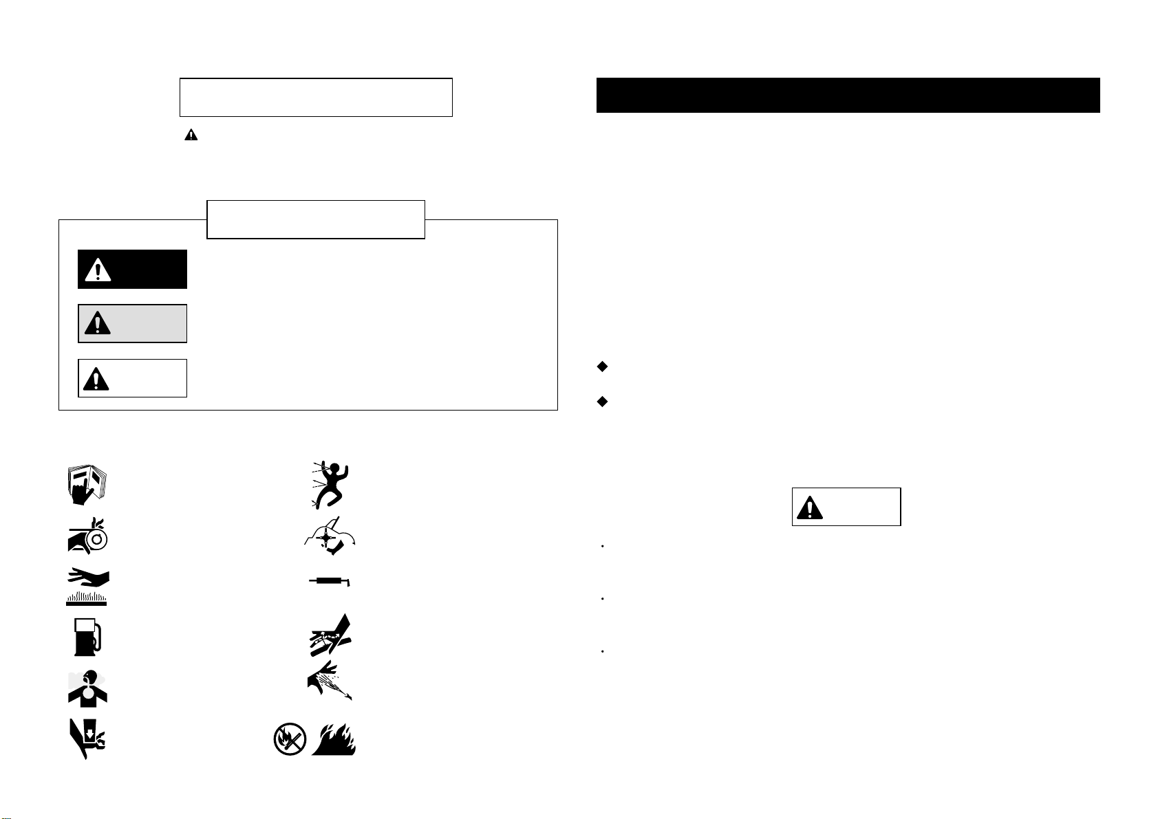
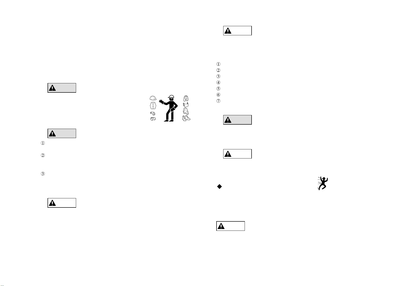
Wear proper clothes that will not be caught in the
machine, and wear protective gear, goggles, shoes,
helmet, and gloves. Provide a first aid kit and secure a
means of communication to deal with an emergency.
Clothes for safety
Avoid such operation
2-1
Do not use the machine when you are tired. When you feel tired while using the
machine, stop the work and take a rest.
Sick people, drunken people, and people under the influence of drugs are not
allowed to use the machine. The visual sense, nimbleness in action, and judgment
will be adversely affected.
When you are unfamiliar with machine operation, read the handling method and
safety precautions to understand them well before operating the machine. Do not
allow children to use the machine.
2-2
When lending the machine to others, an unexpected accident may occur because they
have no knowledge about the safety precautions and handling method shown in the
operation manual. Hand over the operation manual and tell them to read it carefully
before using the machine, explaining the handling method well.
When lending the machine to others2-3
Do not operate the machine with mown grass, dust, etc. accumulated in the cover or around
the engine or the transmission, otherwise fire or other trouble may result. Remove them
carefully. Improper maintenance and incorrect operation and dry grass mowing might
cause fire. Clean and check the machine as shown below before and during work.
Remove dry grass, dust, and other obstacles from around the muffler and engine.
Check the fuel hose for cracks due to deterioration.
Check for fuel leakage during fuel supply.
Fuel supply during engine operation is prohibited.
Check the wiring to prevent fire due to a short circuit.
Inspect the fuel tank and carburetor for fuel leakage due to operation on a slope.
Be sure to carry a fire extinguisher and water etc. when mowing dry grass.
Prohibition of nighttime traveling and work
The machine is not provided with any lighting equipment. Do not operate the machine at
nighttime or when the visibility is poor due to bad weather, etc.
2-5
Do not remodel the machine. Use genuine parts for maintenance to ensure safety.
Remodeling of the machine prohibited2-6
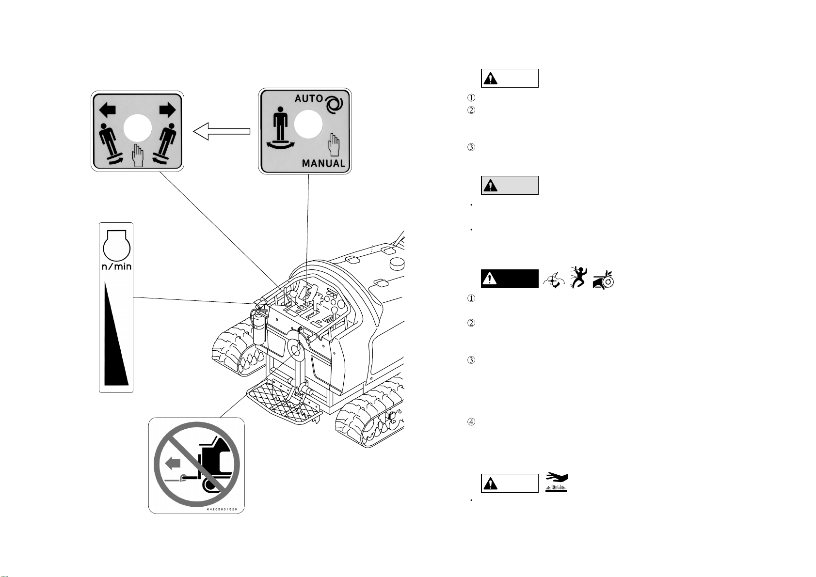
The antiscattering chain is used to prevent stones, etc. from scattering forward during
mowing, thereby preventing damage to human beings, buildings, vehicles, etc. Refer to "6.
Knife frame" in the parts catalog for the installation method.
Antiscattering chain
Fire prevention2-4
Observe the precautions in "1. Precautions as to use" and "2. Safety operation" and pay
sufficient attention to the area around the machine during operation.
- -5
CAUTION
WARNING
WARNING
CAUTION
CAUTION
WARNING
CAUTION

12345678
17
910 11
12
13 14 15 16
3.Part names
No.
1
2
3
4
5
6
7
8
9
Name Name
Handle
Side brake lever
Throttle lever
Traveling lever
Knife clutch lever
Mower portion (Hammer knife)
Protection plate
Protection plate frame
Emergency switch
Step
Sprocket
Crawler
Bottom roller
Front roller
Knife guard
Muffler
Fire extinguisher
No.
10
11
12
13
14
15
16
17
4.Features
This energy-saving type large mowing machine with a diesel engine is manufactured for
professional use especially for slope land operation. The mowing width is 154 or 170 cm,
and the maximum output is 26.5 kW. The machine is ideal for mowing on river banks,
skiing ground and major roads, as well as in other large areas.
The rubber crawler ensure great hill climbing ability, and the low center of gravity permits
safe work even on a slope. The crawler section is provided with a seesaw roller mechanism
to cope with pitching, and the projections inside the crawler are made long to prevent
crawlers from coming off. The grease cylinder used for crawler tension adjustment is easy
to operate.
The machine travels hydraulically at variable speed. The single traveling lever permits
simple operation to move the machine forward and backward, change the speed, and turn
the machine. The position of the traveling lever can be selected from five angles, ensuring
satisfactory operation and improvement of work efficiency.
The hydraulic system permits easy adjustment of mowing height. The special structure of
the knife frame permits long grass cutting length and easy collection of cut grass. The
grass stop shaft (option) makes the cutting length shorter.
The step (simple riding unit) keeps the machine horizontal by using an angle sensor so as to
enhance safety of the operator.
The hammer knives are attached to move freely and the structer lessens impact of stones
and other obstacles when they hit against the hammer knives, hardly causing damage to the
hammer knives.
The hammer knife is made of heat-treated special tough steel, ensuring sharp cutting and
durability and permitting use of both sides by changing the right and left knives. The
hammer knives are attached by bolts and nuts, permitting easy change.
The four-cylinder diesel engine with a starter is easy to start, and the forced lubrication
system and large oil pan can withstand the instantaneous maximum inclination of 35
degrees.
The hitch method is adopted to install the mower portion, permitting easy
installation/removal of the portion.
- -6

5.Specifications
HMA1560 HMA1720
1,717mm 1,910mm
30 7.2cm(51P)
Forward: 0-6.5 km/h
Backward: 0-4.5 km/h
Belt tension type
3-28 cm(max. 42 cm)
(Mowing width Operation speed 0.7)
30
35 7.2cm(51P)
120 blades 140 blades
154cm 170cm
70 are/h (6.5 km/h) 77 are/h (6.5 km/h)
16.6kPa
1,470kg
1,535kg
14.6kPa
1,510kg
1,575kg
Dimensions
Total length
Total width
Total height
Engine
Rubber crawler
Speed change
(Hydraulic variable speed)
Hammer knife
Knife clutch
Mowing height
Mowing width
Efficiency
Max. operating inclination
Ground pressure
Dry weight
Curb weight
3,000mm(3,200mm Foot step)
1,350mm
Mitsubishi Diesel S4L2-E231KM 1.758L (1,758 cm3)
Max. output: 26.5 kW/2,800 rpm (36 PS/2,800 rpm)
Fuel tank: 33 L (dm3)
The idling speed of the engine is approx. 1,500 rpm. Set the idling speed to avoid sympathetic
vibration with the machine. The engine revolution may reach 3,000 rpm under no-load condition.
For transportation of the machine, give attention to the width of the loading space.
Inspect the machine according to "13. Maintenance schedule."
Supply the specified quantity.
Don't use old oil.
Lubrication the friction surfaces of each part.
6. Inspection before use
6-1. Lubrication to each part
Approx. 28 litters of hydraulic oil is in the hydraulic tank. Place the machine horizontally
and check that the level of the hydraulic oil is at the center of the oil gauge.
Change the hydraulic oil one year or 500 hours later, whichever comes earlier.
Change the filter when the hydraulic oil is changed.
When the hydraulic oil is emulsified or its transparency is lost even slightly, change it
instantly.
Supply the hydraulic oil, Shell Tellus ST46 or TX46(ISO VG46) or its equivalent.
6-2. Inspection of hydraulic oil
Refer to the diesel engine operation manual for the method of handling the engine.
6-3. Hydraulic oil change
- -7
CAUTION
CAUTION
CAUTION

Supply oil constantly to the inlet/outlet of the wire and the joint of each part to prevent
rusting. Supply grease to the grease nipple every 50 hours.
6-4. Lubrication of friction surface of each part
50h
Crawler [26 places]
Fulcrum of knife frame [2 places]
Operation lever and neutral positioning [8 places]
Tension [3 places]
- -8

Ordinary bolt
8 (80)
18 (180)
36 (360)
60 (600)
90 (900)
M 6
M 8
M10
M12
M14
Heat-treated bolt
16 (160)
36 (360)
72 (720)
120 (1200)
Bolts are used for each part. After initial use of the machine, the bolts and nuts may get loose.
Tighten loose bolts and nuts.
7. Tightening each part
8. Engine starting sequence
Optimum tightening torque: N.m (kgf.cm)
Before starting the engine, read the diesel engine operation manual to
thoroughly understand the contents.
Put on the side brake and set all driving units at the neutral position.
Check that the covers are at correct positions and that there is no one around the
machine, and confirm safety before starting the engine.
Do not start the engine in a room without an appropriate ventilator.
Check that the knife clutch lever is disengaged before starting the engine.
8-1. Engine start
8-2. Engine start.operation method
Set the throttle lever in the high-speed range.
Check the instruments.
[Key] [ON] (Energization)
Start
After the glow lamp goes out
[Key] [S] (Start)
Operation
[Key] [ON] (Operation)
OFF
ON
S
OFF
ON
S
OFF
ON
S
OFF
ON
S
[OFF]
[Start]
Fuel gaugeFuel gauge
[Energization]
[Operation]
8-3. Engine stop method
Return the throttle lever to the slow-speed position.
Turn OFF the switch and remove the key.
Park the machine in a horizontal state, turn off the engine, and check that all movable sections
have stopped. Then put on the side brake and remove the key before leaving the machine.
Never park the machine on a slope.
8-4.
Precautions to take when leaving the machine
Glow
lamp
Charge
lamp
Oil pressure
lamp
Glow
lamp
Charge
lamp
Oil pressure
lamp
Glow
lamp
Charge
lamp
Oil pressure
lamp
- -9
WARNING
CAUTION

Check that the operating condition of each part especially the safety of the side brake,
traveling lever and hammer knife mower before operating the machine.
Operate the machine at slow speed so that the machine can be stopped immediately in
any case.
Remove obstacles from the operation area so that you and other people around the
machine will not be injured.
9-1. Machine operation
9. Machine operation
Pull the knife clutch to your side to engage it, and push it forward to disengage it.
The engine cannot be started when the knife clutch is engaged.
9-2. Knife clutch
The traveling lever is at the center of the
rear section of the machine. Push it
forward to move the machine forward, and
pull it back to your side to move the
machine backward. Adjust the speed by
changing the inclination of the lever.
Turn the traveling lever to the direction of
the desired direction of turning. Return the
lever to the original position, and the
machine will move straight.
The position of the traveling lever can be selected from five angles. Change the position of
the lever according to the operating conditions.
9-3.Traveling lever
Traveling lever
Mowing height
adjustment
switch
Forward
Backward
Mowing height
Low
High
When driving the machine on a steep slope, the machine will not stop even if the traveling
lever is released. When driving the machine on a slope, hold the traveling lever with one
hand and the handle with the other hand so that the machine can stop any time. Never release
them during traveling.
The hydraulic method, in which a solenoid valve and cylinder are used, is adopted for
mowing height adjustment. Tilt the mowing height adjusting switch on the traveling lever to
your side to raise the mowing height, and tilt it forward to lower the mowing height. The
mowing height adjusting range is 3-30 cm. The knife rotation above the range is prohibited
for safety's sake though the mower portion itself can be raised higher for the sake of
transportation or storage. Adjust the mowing height appropriately. Adjust the mower portion
lowering speed with the valve unit, which will be seen at the back of the fuel filler port when
the right side cover is opened.
9-4. Mowing height adjustment
The working speed is hydraulic variable within the range of 0-6.5 km/h for forward operation
and 0-4.5 km/h for backward operation. Adjust the speed appropriately with the traveling
lever according to the condition of the geography and grass.
9-5. Working speed
- -10
CAUTION
WARNING
OFF
ON
Knife clutch lever
Engage the knife clutch right before starting mowing operation. Be sure to leave it
disengaged during any operation other than mowing.
Since the knife shaft rotates by the centrifugal force, engage the clutch halfway until
the rotation is normal. Do not engage the clutch completely at a stroke.
CAUTION

The step is kept horizontal at all times by the angle sensor, automatic level control box and
electric cylinder. The "step control changeover switch" at the left side of the traveling lever
permits switching from AUTO to MANUAL, and vice versa. When the step control
changeover switch is in the "MANUAL" position, the "step control manual switch" under the
step control changeover switch permits control.
However, be sure to set the step control changeover switch in the "AUTO" position during
mowing. Use the manual position only when maintaining the machine, the automatic control
circuit fails, or some other emergency arises. When the automatic circuit fails, replace the
part with a new one immediately. Do not operate the machine for mowing on the manual
control step.
9-6. Step (simple riding unit)
9-7. Transportation on public roads
For transporting this machine through public roads, follow the appropriate laws of the
country where it is moved.
9-8. Alarm buzzer
When the alarm buzzer sounds, the engine is overheated. Stop operation, and remove dust
that is jamming in the radiator or air cleaner etc.
When the machine is not to be moved, pull the side brake lever fully to your side, and the
brake will be applied to the hydraulic motor and the traveling lever will be locked at the
neutral position.
When the balance is lost, the hammer knife will vibrate because it is rotating at high speed,
which is very dangerous. Exercise care sufficiently.
9-9. Side brake
10. Hammer knife
Both sides of the hammer knife are sharpened. When one side is worn, remove the pair
of knives, and attach them reversely. The knife is attached to the knife shaft mounting
10-1. Use of both sides of hammer knife
hitch section by 11 mounting pin 32 and the nut with disc washer, and the knife can be
removed easily.
Attach the mounting pin in the same direction as before.
The knife shaft assy is balanced when shipped from our factory; therefore, unless all the
knife blades of the same weight each are replaced at one time, or unless replaced
symmetrically on the right and left portions of the knife shaft, the weight balance may be
lost and vibration may be generated.
Since the hammer knife shaft assy are rotated at high speed, pay attention to the weight
balance when replacing the hammer knife.
10-2. Replacement of hammer knife
When both sides of the hammer knife blade are worn, grind each blade in a manner that
the weight of each blade will be the same as much as possible.
When the weight balance of the hammer knife shaft assy including the knife blades is
poor, the hammer knife shaft assy will generate vibration, breaking the machine.
10-3. Grinding the hammer knife
11-1. Operation on slope
When operating the machine on a slope, move the machine upward gradually from the
bottom of the slope along the contour line.
When operating the machine on a slope, push the traveling lever forward to move the
machine forward, pull it to your side to move the machine backward, and change the angle
of the traveling lever to change the speed. Turn the traveling lever in the direction, in
which the machine is to be turned. Release the traveling lever, and the lever will be set in
the neutral position, stopping the machine. For safety, stop the machine so that it will be
positioned along the contour line. When stopping the machine vertically on a slope, the
machine may not be able to stop immediately because of the inertia of the traveling
machine. The machine is provided with a hydraulic traveling system, and the step is
provided with an automatic level control sensor. When the machine is therefore turned
toward the bottom of the slope, the machine will turn smoothly because the center of
gravity of the machine changes favorably, also ensuring the operator since this way can
avoid his position just below the machine during turn.
11. Operation on slope
- -11
CAUTION
DANGER
CAUTION
CAUTION

11-2.
Precautions as to operation on a steep slope
Be sure to observe the following matters when using the machine on a
steep slope of 20 degrees and above.
Do not operate the machine when there is a risk of falling or slipping.
Before starting operation on a steep slope, check for holes, rocks, tree roots, illegal
throwaways, etc. Remove them, if any, and then carefully operate the machine.
On a steep slope, operate the machine along the contour line, and turn the machine in a
place with a small angle of inclination as much as possible.
Do not operate the machine on a steep slope of 30 degrees and above. Since the
machine is very likely to fall down sideways on such a steep slope.
When ropes are used on a steep slope while working together with an assistant worker,
the machine may move to a very steep slope with an angle of inclination that exceeds
the allowable angle and the risk of falling down sideways will increase, preventing
safe operation. As a maker of the machine, we will prohibit such operation.
12-1. Precautions as to maintenance
12. Precautions as to maintenance
Thoroughly understand the method of required maintenance.
Do maintenance in a dry, clean place.
Do not supply oil or do maintenance while the machine is operating.
Do not bring your hands or feet near the driving and operating parts.
Stop all driving parts, and operate respective control units to release the pressure.
Install all parts in a satisfactory state.
Repair or replace damaged parts immediately.
Replace worn or damaged parts.
Do not remodel the machine. Use genuine parts for maintenance to ensure safety.
Remove dust, grease, and oil adhering to the machine.
Remove the minus (-) wiring from the battery before maintaining the electric system.
12-2.
Prevention of damage due to high-pressure oil
The high-pressure oil, when sprayed over the skin, will cause serious injury.
Release the pressure before removing the high-pressure line, hose, and joints.
Check the tightness of all joints before starting operation.
Use a small piece of cardboard to check for leakage. When your skin is sprayed with high-
pressure oil, you must see a doctor within two to three hours.
12-3. (Diesel fuel) Precautions as to fuel handling
Use of fire is prohibited strictly during fuel supply.
Stop the engine to cool it outdoors before supplying fuel.
To prevent fire, keep the machine clean without dust, grease, or oil at all times.
Wipe off spilt fuel cleanly.
Refer to the battery instruction manual for the method of handling the battery.
12-4. Precautions as to battery handling
Use of fire is prohibited strictly when checking or charging the battery. The electrolyte is
dilute sulfuric acid. Do not allow it to contact your body or the machine. If the electrolyte
adheres to your body or the machine, wash it off with water immediately. Especially when
it enters your eyes or you swallow it by mistake, see a doctor immediately.
When removing the cable from the battery, remove the negative side first, and when
attaching the cable to the battery, attach the positive side first. When the sequence is
reversed, tools may touch the machine and cause a short circuit, generating sparks.
Connect the battery cables correctly to the positive and negative sides. If the direction of
connection is wrong, the battery and its electric equipment will be damaged.
- -12
WARNING
DANGER
WARNING
DANGER
CAUTION

13. Maintenance schedule
Refer to the diesel engine operation manual for the method of handling the engine.
Inspection, adjustment, replenishment and cleaning
Replacement
Engine Main unit
Knife section
Others
Maintenance
Engine oil
Oil filter
Fuel filter
Electromagnetic pump filter
Air cleaner element
Air cleaner urethane
Cooling water (qty, leakage, etc.)
Fuel (qty, leakage, etc.)
Hydraulic oil (qty, leakage, etc.)
Hydraulic oil filter
Tightening of hydraulic hose/joint
Electrolyte
Radiator core
Side brake
Traveling lever
Neutral position
Emergency switch operation
Step operation
Operation of respective switches and meters
Lighting of pilot lamp
Knife tension operation
Strength of knife tension
V-belt tension
Crawler tension
Breakage of hammer knife
Looseness of knife mounting bolt
Knife shaft bearing
Dust-proof cover and protection plate
Greasing each section
Looseness of screw in each section
Accumulation of dust
Visible damage
Initial
After 10 hr
Hydraulic
motor oil Initial
After 200 hr
Before
use
10hrs every
50hrs every
200hrs
every
500hrs
14-1. Knife
14. Belt adjustment
Remove the knife shaft cover and adjust the tension of the belt put on the B3 V-pulley
30150 and knife shaft V-pulley by using the tension pulley adjusting bolt.
Adjust the tension of the belt put on the B3 V-pulley 30175 and B6 V-pulley by using
the lever adjuster.
Adjust the tension of the belt put on the B6 V-pulley and engine pulley by using the
knife adjusting rod.
Knife adjusting rod
Lever adjuster Tension pulley adjusting bolt
Knife shaft V-pulley
B3 V-pulley
B6 V-pulleyEngine pulley
14-2. Hydraulic pump
Adjust the tension of the belt put on the engine pulley and hydraulic pump pulley by using
the lever adjuster.
- -13
CAUTION

15-1. Crawler tension
15. Crawler
Adjust the crawler tension by supplying grease to the grease cylinder. Make adjustment
so that the crawler tension will be the same on both sides.
Grease cylinder M14 bolt
Grease nipple
Excessive crawler tension will cause the front roller to lose the clearance, causing
the crawler to come off easily and the machine to break easily. Exercise care.
2mm
15-2. Installation.removal of crawler
When removing the crawler, loosen the M14 bolt (width across flats: 22) on the grease
cylinder, remove the grease, return the front roller to the original position, lift the crawler that
is to be removed above the ground, and then remove the crawler. Reverse the order of
removal when installing the crawler. Refer to the preceding paragraph for the crawler tension.
15-3. Prevention of crawler tearing loose
Check that the crawler is not slackened and the crawler tension is adjusted appropriately.
15-4. Greasing the crawler
The seesaw roller fulcrum shaft in the crawler section is provided with a grease nipple.
Supply grease to the nipple every 50 hours. Use Kyodo Yushi Excelite EP No.2(ISO VG2) or
its equivalent. (Refer to "6-4. Lubrication of friction surface of each part")
16. Adjustment of traveling section
Conduct the following work before adjusting the traveling section:
Remove the crawlers on both sides, or place the machine on a stable base to lift the
crawlers on both sides.
Remove the rear cover.
When lifting the machine, be sure to use an appropriate support to
completely secure the machine.
- -14
CAUTION
CAUTION

16-1. Adjustment of neutral position of piston pump
Loosen the mounting bolts of the neutral lever mounting bases for the pump on both sides
to keep the bolts loose.
Return the side brake lever to unlock the traveling lever.
Start the engine, and move the neutral lever mounting bases for the pump by using a stick,
etc. to determine the neutral position.
The engine is rotating. Be careful of the pulley, belt, sprocket (crawler),
etc. during operation.
When the neutral positions of both bases are determined, stop the engine and tighten the
mounting bolts.
Start the engine again to check that the sprocket (crawler) will not rotate.
Pump
Mounting bolt
Left neutral lever
mounting base for pump
Right neutral lever
mounting base for pump
16-2. Adjustment of neutral position of traveling lever
Loosen all the lock nuts of the M10 right-/left-hand thread rods.
Turn the two rods at right and left to adjust the length so that the lock shaft of the traveling
lever will be set in the neutral stopper groove when the side brake is pulled.
Tighten all the lock nuts of the rods and check that the traveling lever is locked completely
when the side brake lever is pulled and that the traveling lever is unlocked quickly when
the side brake lever is returned.
Lock nut
(left-hand thread)
Lock nut
(right-hand thread)
Lock shaft
Groove
Groove
Traveling lever
Neutral stopper
M10 right-/left-hand thread rods
- -15
CAUTION

16-3. Confirmation after adjustment
Stop the engine and move the respective levers to check for interference.
Check that the machine is in the neutral position and will not move even if the engine is in
the full-throttle state.
(When the side brake lever is pulled and returned)
After moving the traveling lever to move the machine, release the traveling lever, and
check that the machine will not move.
After the above-mentioned adjustment, confirm the following:
17. Engine
(Diesel fuel)
Precautions as to handling of engine
a) Use diesel fuel as the engine fuel.
b) The machine is to be operated under severe conditions such as vibration, slopes, and dust.
Change the entire engine oil 10 hours after the initial operation. Then while continuing
inspection and replenishment before use, change the entire quantity every 50 hours
thereafter.
Change all the oil filters simultaneously as well.
When using the machine in a dusty place, change oil and the oil filters more frequently.
The quantity of the engine oil is 7.9 liters. Use the diesel engine oil in the service class CC
or above specified by the API standard.
c) When air is sucked in the fuel system of a diesel engine, the engine will not be started.
Inspect and maintain the diesel engine at all times to prevent entry of air into the fuel
system. Operation will be difficult when the fuel filter and electromagnetic pump filter are
clogged with dust or when water remains in them. Drain water or clean filters every 50
hours. Replace filters with new ones every 200 hours.
d) Cover the suction port of the air cleaner with polyurethane and cleaner cover at all times
during operation. Be sure to clean the air cleaner element before operation, and replace
the element with a new one every 200 hours.
e) Mix antiseptics (long-life coolant) into water, and put the mixture in the reserve tank up to
the MAX position as a radiator cooling water. Change the cooling water every 50 hours.
Check and supply the cooling water before operation. When the temperature is likely to
drop below the freezing point, use an antifreeze mixture. When the radiator fins are
clogged with dust, blow air to clean them.
Refer to the diesel engine operation manual for the method of handling the
engine.
There is a risk of a skin burn. Do not open the radiator cap during or right after
operation.
18. Hoisting
Precautions as to hoisting
a) Qualification necessary to use a crane to hoist the machine
For hoisting the machine, follow the appropriate laws of the country where it is hoisted.
b) Hoisting procedure
Lower the mower portion until it touches the ground.
Pull out the four hoisting hooks and secure them with pins. Hook the wire ropes
completely with shackles. Use wire ropes with sufficient strength. Be sure to use four
ropes of 2.5 m or more in length.
Pay attention to the position of the center of gravity during hoisting to balance the
machine sufficiently. Do not approach the machine inadvertently during hoisting.
- -16
CAUTION
CAUTION
CAUTION

19. Attaching/detaching the mower portion
Be sure to install and remove the mower portion in a flat horizontal place. Stop the
engine unless it is necessary to move the attachment mounting base up and down or
to move the machine forward and backward.
19-1. Removal of attachment
(The numbers in [ ] in the text correspond to the parts catalog Nos.)
Remove the intermediate shaft belt cover [17-44] and right crawler cover [6-47], and then
remove the belt [7-30] that connects the machine and the mower portion.
Remove the clip pin [6-75] and remove the lock pin [6-74].
Set the cylinder single-/double-acting changeover switch [12-40] in the "double-acting"
position, and lower the attachment mounting base.
After confirming that the hitch sections are separated, slowly move the machine
backward, and the operation is complete.
Attachment
mounting base
Hitch sections
Lock pin mounting hole
mower portion (Hammer knife)
19-2. Installation of the mower portion
(The numbers in [ ] in the text correspond to the parts catalog Nos.)
While engaging the hitch sections, slowly move the machine forward, and raise the
attachment mounting base to engage the hitch sections.
After confirming that the hitch sections are engaged completely, attach the lock pin [6-74]
and secure it with the clip pin [6-75].
Set the cylinder single-/double-acting changeover switch [12-40] in the "single-acting"
position.
After attaching the belt [7-30] and adjusting the tension, attach the right crawler cover [6-
47] and intermediate shaft belt cover [17-44], and the operation is complete.
19-3. Hydraulic cylinder single-/double-acting changeover
Before starting ordinary operation, be sure to set the cylinder single-/double-acting
changeover switch in the "single-acting" position, and change it to the "double-acting"
position before installing or removing the mower portion.
Operation with the changeover switch in the "double-acting" position will cause the
hitch sections to be subjected to a load when the machine climbs over a large stone
or some other obstacle, causing machine failure.
20. Gear oil change for traveling motor
The speed reducer of the hydraulic motor for traveling is filled with 0.35 litter of gear
oil. Flush the speed reducer 50 hours after initial operation and every 200 hours after
that, and after each flushing, fill the speed reducer with a new gear oil(ISO VG140).
Unless the oil is changed according to the specified time, the motor failure will result.
Be sure to change oil as specified.
- -17
CAUTION
CAUTION
CAUTION

Starter switch connection 4-pole ON-ON switch
5 2 11 8 9 12 6 3 10 7 4 1 1 6 3 4 5 2
Electric
cylinder
Fan
control
unit
Solenoid valve
for fan rotation
Solenoid valve
for mowing height
Safety
switch
Fuel
pump
Fuel
gauge
Starter Thermo
switch
12V 80Ah/20HR
95D31R battery
Oil
pressure
switch
Alternator
Engine
Charge
lamp
Solenoid Glow plug
Flat connector
(AV0.85)
Red
and
black Red
White Blue
Flat connector
Tank
unit
Alarm
buzzer
Water
temperature gauge
Water
temperature gauge
Thermo
switch
Glow
lamp
Glow
timer
Emergency
switch
Safety relay
Glow relay Relay
Oil
pressure
lamp
Brake release
solenoid
Horizontal
controller
box
Inclination
sensor
Glow timer
4
4
44
2
22
857
3
53
3
3
1
11
6RPLES
Control timer
Relay N.C. relay
N.C.
relay
Safety relay
2-pole ON-OFF-ON switch
Solenoid valve for
single-/double-acting
changeover
Control timer
– CAUTION –
The wires with the same numberd
mark are connected to one wire
inside the wiring system.
The single wires with mark without
number and the wires connecting
the wires of the same numberd
mark are connected to a grounding
wire at the back of the electric
equipment box.
B
OFF
1
2
MSG2
Yellow and red
(AV1.25)
Yellow and red
(AV1.25)
Yellow
and red
(AV2)
Yellow
and red
(AV1.25)
Yellowand red
(AV1.25)
Yellow
(AV5)
Black(AV1.25)
Green and red
(AV1.25)
Blue(AV2)
Orange(AV0.85)
Red(AV0.85)
(AV1.25)
50A 5A 5A 5A 5A 5A 5A
20A 20A 20A
5A
(M6)
Red
(AV5)
(M5)
(M5)
G2
G1
(M4)
(M4)
B
SM
Red(AV2)
Red(AV2)
Red(AV1.25)
Gray(AV1.25)
Black and yellow(AV0.85)
Red and white(AV0.85)
Red and black(AV0.85)
White(AV2)
Red(AV5)
Black(AV30)
Pink(AV3)
White and yellow(AV0.85)
Blue(AV5)
1
65
1
12
2
3
43
4
7
5
6
43
243 1243
Green(AV5)
Yellow(AV0.85)
Blue(AV5)
Black
(AV30) Black
(AV5)
Black
(AV0.85)
Black
(AV0.85)
Green
(AV0.85)
Red and white
(AV0.85)
Red and white(AV0.85)
Yellow and black
(AV0.85)
Black
(AV0.85)
Black(AV0.85)
Black(AV3)
Yellow and blue(AV0.85)
Yellow and red(AV0.85)
White(AV0.85)
Black(AV1.25)
Black(AV1.25)
Yellow and black(AV0.85)
Blue(AV0.85)
Green(AV0.85)
Red(AV1.25)
Blue and white(AV0.85)
Yellow and red
(AV0.85)
White and black
(AV0.85)
Yellow
and blue
(AV0.85)
(M12)
(M4)
(M5)
(M6)
(M6)
(M6) (M8)
(M6)
L
B
P
R
L
R
L
R
PS
E
(M6)
(AV0.85)
Yellow
(AV5)
50A
Red and white(AV1.25)
White(AV5)
White(AV0.85)
Black(AV1.25)Black(AV1.25)
Black(AV3)
Black(AV2)
Black(AV1.25)
Black(AV1.25)
Black
Brown(AV5)
Brown(AV1.25)Brown(AV1.25)
Red(AV1.25)
Red(AV3)
Red and yellow(AV2)
White and
red(AV2)
White and red(AV2)
Red(AV2)
Red(AV0.5)
White(AV0.5)
Black and
white(AV0.5)
Black(AV0.5)
Green(AV0.5)
Brown(AV0.5)
Sky blue(AV0.5)
Red(AV2)
Black(AV2)
White and red(AV2)
White(AV2)
White(AV2)
Black(AV2)
White
(AV2)
Blue(AV1.25)
Blue(AV1.25) Blue(AV1.25)
Blue
Blue
Blue
White
Black
Blue
Green
Green
Green
White
Black
Red
Green
Blue(AV1.25)
Green(AV1.25)
Green(AV1.25)
Green(AV1.25)
Brown(AV0.85)
Blue and yellow
(AV0.85)
Black
(AV1.25)
Black
(AV0.85)
Black
(AV0.85)
Red and yellow(AV0.85)
(M6) T(M6)
E
B1(M5)
M(M8)
(M8)
(M5) (M5)
(M5)
(M6)
(M6)
(M4)
(M5)
+E
S
B
-
(M6)
(M6)
(M6)
(M6)
(M6)
(M6)
(M6)
(M6)
(M6)
(Flat connector)
21. Wiring diagram - -18
Other manuals for Baroness HMA1560
1
This manual suits for next models
1
Table of contents
Other Kyoeisha Lawn Mower manuals

Kyoeisha
Kyoeisha Baroness LM315GC Setup guide

Kyoeisha
Kyoeisha BARONESS LM56GC Operation manual

Kyoeisha
Kyoeisha Baroness LM531 User manual

Kyoeisha
Kyoeisha Baroness LM1808 User manual

Kyoeisha
Kyoeisha Baroness LM531 Operation manual

Kyoeisha
Kyoeisha Baroness LM315GC Setup guide

Kyoeisha
Kyoeisha Baroness LM282 User manual
Popular Lawn Mower manuals by other brands

MTD
MTD Series 830 Operator's manual

Scag Power Equipment
Scag Power Equipment Cheetah SCZ52V-730FX Operator's manual

Craftsman
Craftsman 917.27688 Operator's manual

MTD
MTD 650 Series Operator's manual

Craftsman
Craftsman 917.377641 owner's manual

Briggs & Stratton
Briggs & Stratton 1696715-00 Operator's manual