Kyoeisha Baroness LM282 User manual

MOWER
Owner's handling manual & parts catalogue
SN 10011
2007
"Required reading"Before using the machine please ensure that you have read this
manual and the operating and instruction manual for the engine.
Compact Light Weight 5-Reel Mower
Riding Type 3-Reel Mower

Safety Warnings .................................................................... 1
Introduction ........................................................................... 1
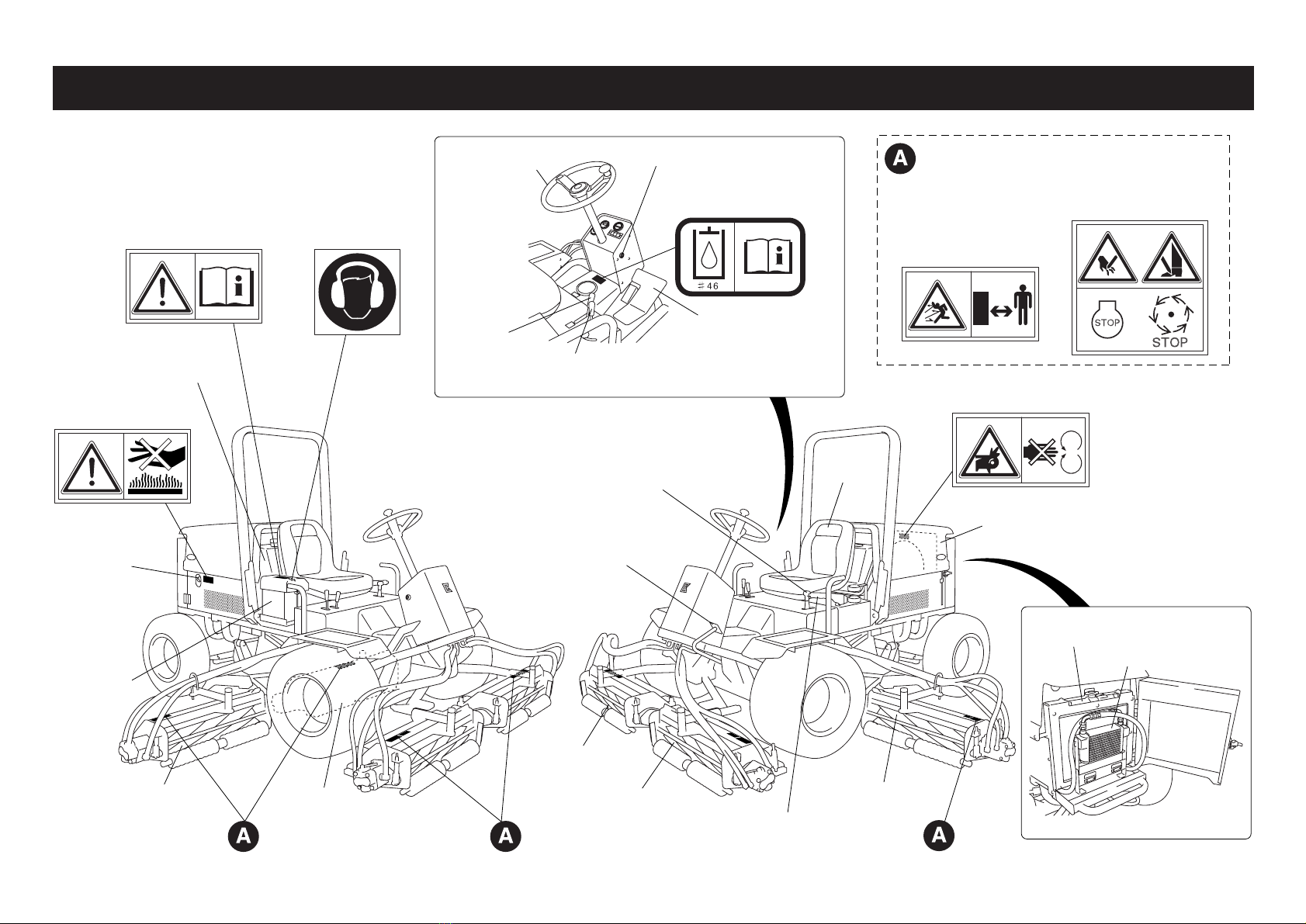
Part Names and Warning / Instruction Label Locations ........ 2
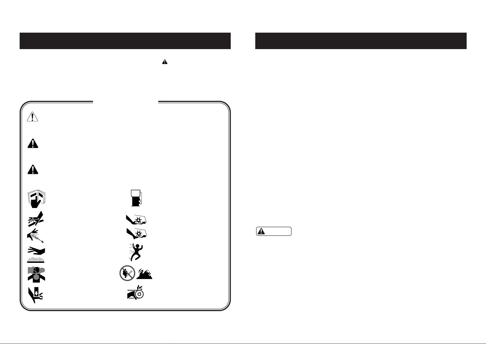
Warning Labels and Instruction Labels ................................. 3
LM282 / LM319 Features ...................................................... 4
Specifications ........................................................................ 4
Operation .............................................................................. 5
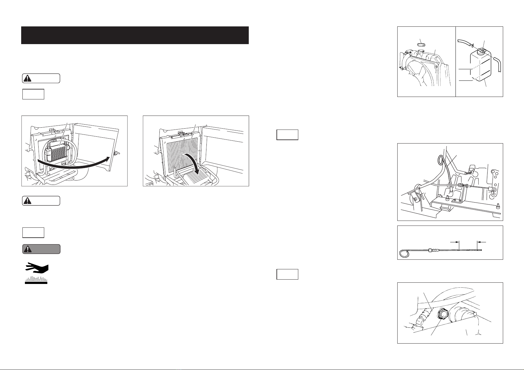
1. Inspection before use ...................................... 5
1-1 Clean the radiator and oil cooler ............... 5
1-2
Inspect the radiator and the water coolant quantity
...... 5
1-3 Inspect and refill the engine oil .................................. 5
1-4 Inspect the hydraulic oil ............................................ 5
1-5 Clean the air cleaner ................................................. 6
1-6 Inspect around the engine ........................................ 6
1-7 Inspect the tires ......................................................... 6
1-8 Inspect the brakes .................................... 6
2. Tighten all parts ............................................................... 6
3. Machine Operation .......................................................... 7
3-1 Machine operation .................................... 7
3-2 Before starting the engine ........................ 7
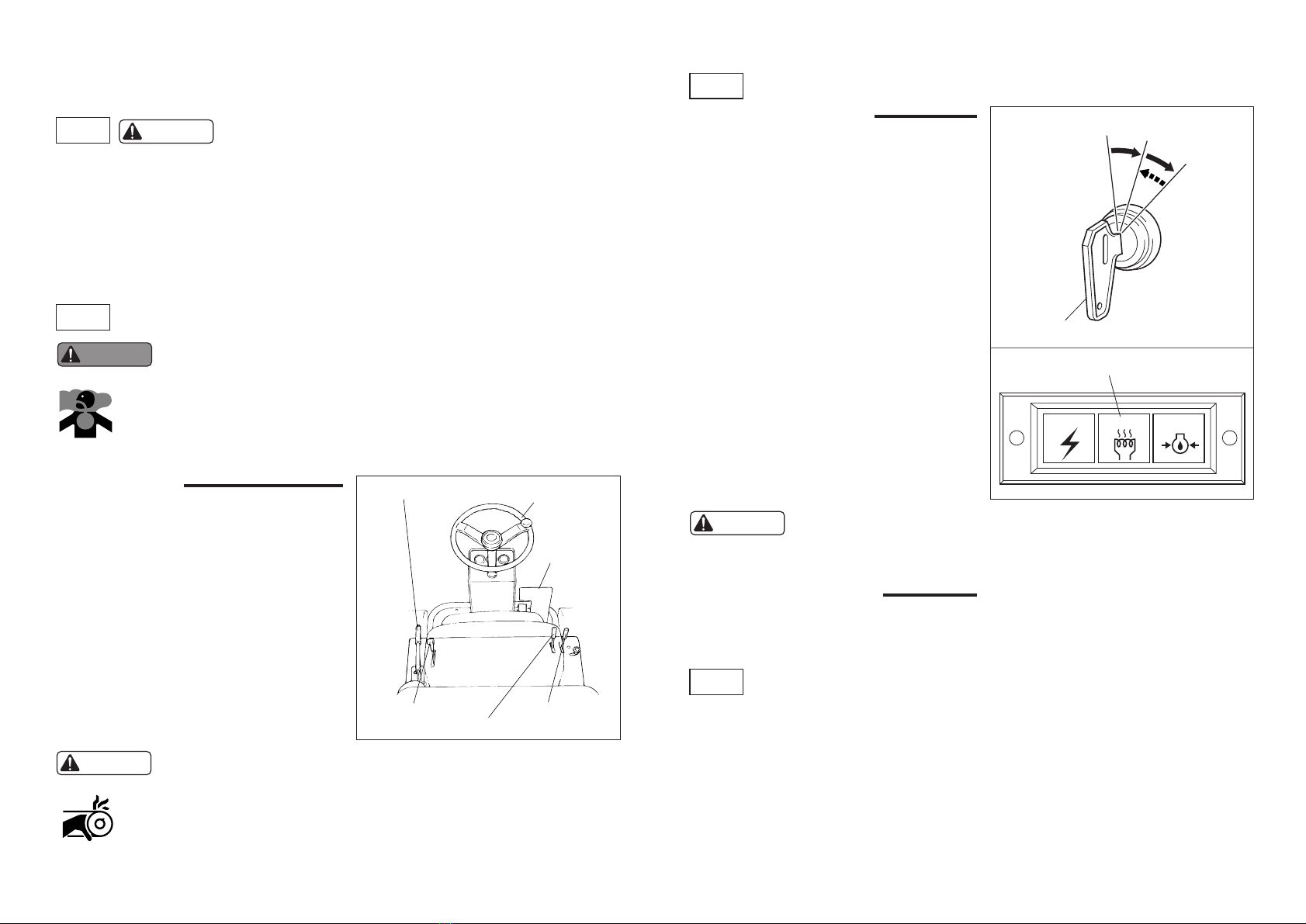
3-3 Starting up and shutting off the engine ..................... 7
3-4 Safety device ............................................................ 7
3-5 Fuel handling precautions ........................ 8
3-6 When leaving the machine ...... 8
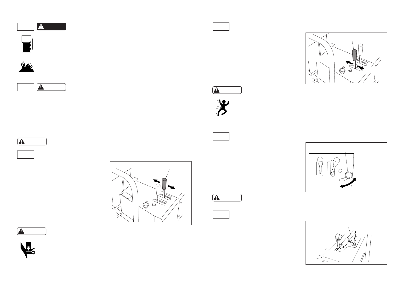
3-7 Reel raise/lower lever ............................... 8
3-8 Reel rotation lever .................................... 8
3-9
Reel reverse-rotation prevention stopper
.... 8
3-10 Side brake ............................................................... 8
3-11 Unload valve ........................................... 9
3-12 Stop valve ............................................... 9
3-13 Reel rotation/stop changeover lever ....... 9
3-14 Adjusting the seat .................................................. 10
Caution
Caution
Caution
Caution
Caution
Caution
Caution
Caution
Danger
Caution
Caution
Danger
Warning
Caution
Caution
3-15 Mower lock lever (LM282 only) .............................. 10
4. Operating the machine .................. 10
5. Gauges........................................................................... 11
5-1 Water temperature gauge........................................ 11
5-2 Hour Meter .............................................. 11
5-3 Fuel Gauge .............................................. 11
5-4 Oil Pressure Lamp ................................................... 11
5-5 Charge Lamp ........................................................... 11
6. Inspection and Maintenance .......................................... 12
6-1 Changing Engine Oil ............................... 12
6-2 Changing Hydraulic Oil ............................ 12
6-3 Applying Grease ...................................................... 12
6-4 Inspecting for Leaks................................................. 12
6-5 Inspecting the Battery ............. 13
6-6 NTN Constant-Velocity Joints ................. 13
7. Maintenance Cautions ................................................... 13
7-1 Maintenance procedures ........ 13
7-2 Preventing injuries from high-pressure oil ....... 13
7-3 Maintenance Schedule ............................................ 14
7-4 Maintenance schedule and specified values ........... 14
8. Mower adjustment.......................................................... 15
8-1 Cutting height........................................................... 15
8-2 Blade adjustment .................... 15
8-3 Lapping .................................................... 16
9. Precautions for machine operation ................................ 16
9-1 hot parts .................................................. 16
9-2 Reel mower ............................................. 16
9-3 Raising the unit........................................ 16
10. Working on a slope ...................................................... 17
10-1 Precautions when working on a slope... 17
11. Safe operation.............................................................. 17
11-1 Safety clothing....................................... 17
Warning
Caution
Caution
Danger
Caution
Caution
Danger
Caution
Warning
Caution
Caution
Caution
Danger
Caution
Caution
Caution
Danger
Caution
Warning
Caution
11-2 When not to operate the unit ................ 17
11-3
When lending the machine to another person
..... 17
11-4 Do not modify the machine.................... 17
11-5
Remove debris from around the muffler and engine
..... 17
11-6 Do not operate the machine at night ..... 17
11-7 Do not drive on public roads.................. 18
12. Long-term storage........................................................ 18
Hydraulic circuit diagram (LM282/LM319) ........................... 19
Electrical system (for both models) ...................................... 21
Parts Catalogue ................................................................... 23
1. Frame parts.................................................................... 24
2. Cover parts..................................................................... 26
3. Front wheel parts ........................................................... 30
4. Rear wheel parts............................................................ 32
5. Pedal parts..................................................................... 34
6. Engine parts................................................................... 36
7. Hydraulic parts A (power steering, cylinder system) ...... 40
8. Hydraulic parts B (reel motor system)............................ 44
9. Hydraulic parts C (wheel motor system) ........................ 48
10. Mower lift arm parts...................................................... 52
11. Mower parts (LM282/#1, #2, #4, LM319/#1, #3).......... 54
12. Mower parts (LM282/#3, #5 LM319/#2)....................... 58
13. Roller assembly parts................................................... 62
14. Accessory parts............................................................ 64
15. Option........................................................................... 64
Caution
Warning
Warning
Caution
Caution
Warning
CONTENTS

Thank you for purchasing a Baroness LM282 Compact Light Weight 5-Reel Mower or a
LM319 Riding Type 3-Reel Mower.
This operation manual serves as a guide to the correct usage, adjustment, and inspection
of the mower. Read this manual thoroughly before operating the mower. Use the mower
only when you have fully understood the contents of this manual.
Your Baroness mower has been shipped only after thorough post-production inspections
and testing, but daily maintenance such as inspections, adjustments, and refuelling is
essential in ensuring the machine maintains its original performance levels.
Caution
• The form of this machine may change gradually.
Please have both the model number and manufacturer's serial number ready before
contacting us with an inquiry.
• The contents of this manual may be changed without notice.
To ensure correct and safe operation, warning labels with a symbol have been placed
on the machine.
These warning labels describe safety precautions and provide important information. Be
sure to observe the warnings and to operate the machine safely.
Explanations of the warning labels used in this manual and on the machine are provided to
ensure safety.
Make sure you read the operating procedures and safety precautions. Operate the mower
only when you have fully understood them.
Keep the warning symbols and their explanations clean. If a label is missing or damaged,
replace it with a new one immediately.
Never remove warning labels from the mower.
-1-
IntroductionSafety Warnings
: Failure to comply with these warnings will result in
serious injury or loss of life.
: Failure to comply with these warnings could result in
serious injury or loss of life.
: Failure to comply with these warnings could result in
injury or property damage.
DANGER
WARNING
CAUTION
Operational precautions
Caution
Warning Labels
No.2 Diesel Fuel
Refer to the
Operation Manual
・・・
WARNING symbol
(High Pressure Oil)
・・・
DANGER symbol
(Hand and Foot Entanglement)
・・・
CAUTION symbol
(Hot Parts)
・・・
WARNING symbol
(Exhaust Gas Hazard)
・・・
CAUTION symbol
(Crush Hazard)
・・・
Fuel
・・・
DANGER symbol
(Open Flame Prohibited)
・・・
CAUTION symbol
(V-belt / Rotating Parts)
・・・
DANGER symbol
(Thrown Objects)
・・・

-2-
Part Names and Warning / Instruction Label Locations
K4205001560
Read the Operation
Manual label
K4205001330
High Noise
Levels symbol
K4205001540
Hot Parts Hazard
label
K4205001600
Cutting Hazard label
K4205001650
Thrown Objects
Hazard label
One of each label is affixed to the top of each of
the mower reel covers.
K4205001530
Rotating Parts Hazard label
K4209000980
Hydraulic Oil Hazard
symbol
Handle
Muffler
Fuel tank Reel rotation lever
Reel
raise/lower
lever
Seat
Mower unit #2
Mower unit #3
Mower unit #4 Mower unit #1 Mower unit #5
Oil cooler
Radiator
Side brake lever
Bonnet
Throttle lever
Accelerator pedal
Brake pedal
Battery
Key switch

-3-
Warning Labels and Instruction Labels
Warning labels and instruction labels have been placed in clearly visible locations near
potential hazards. If a label is damaged or missing, replace it with a new one.
: Cutting of Hand
Placing your hand near the fan and the belt while
the engine is running could result in injury.
Pressurised Oil symbol
Read the operation manual.
: Cutting of Hand or Foot
Risk of injury unless the rotating part is stopped
and the engine shut off.
: Thrown Objects
Always keep the mower at a safe distance from
people.
: Read the Operation Manual.
: High Noise Levels
It is recommended that you wear ear protection
to protect your ears from exposure to high noise
levels.
: Hot
To avoid risk of burns, do not touch.
Caution
Caution
Warning
Danger
Danger
Danger

-4-
LM282 / LM319 Features Specifications
LM282 / LM319 Features
• The LM282 and LM319 employ an oil hydraulic-type full-time 4WD system.
• Vertical shafts are employed at the traction points to reduce shaking.
LM282 Features
• The LM282 is lighter than other riding-type 5-reel mowers and it uses broad, low-pressure
tires to reduce damage to the grass.
• The mower lock lever (manually operated) enables the following.
• The raising and lowering times for mower units #4 and #5 can be reduced if the mower
units are raised or lowered when the mower lock lever is down. This is ideal for moving
around the golf course.
• When mower units #4 and #5 are stored in their raised positions, applying the mower
lock lever prevents them from falling.
• When the mower lock has been applied to mower units #4 and/or #5, the mower can
be set to triple mowing or to quadruple mowing on the left and right, for example,
enabling you to adjust the mowing width to suit the conditions.
Model
Drive type
Length
(during operation)
Height
Weight
Speed
Front wheels
Rear wheels
Model
No. of cylinders
Exhaust volume
Power output
Engine RPM
Fuel consumption rate (at 3,000 rpm)
Mowing width
Mowing height
Reel cutter
Mower
dimensions
Wheels
Engine
LM282 LM319
4-wheel drive
250cm
180cm 199cm
315cm 203cm
130 cm (handle); 183 cm (sunshade frame)
1,150kg 1,025kg
0 to 14.4 km/h (hydraulic variable speed drive)
24 x 13.00-12 4P
23 x 8.50-12 4P
Kubota D1105 vertical-type water-cooled four-cycle diesel
3
1.123L (1,123cm3)
Max: 19.4 kW (26.4 PS) / 3,000 rpm
1,200 to 3,000 rpm (when idling)
255 g/kW.h (188g/PS.h)
282cm 180cm
10 to 60 mm
66cm x 5
66cm
x
2, 76cm
x
1
Reel diameter: 16.3 cm
Width (when being moved from
one location to another)

• If debris has accumulated in the radiator and oil cooler, air-blow clean.
-5-
Clean the radiator and oil cooler
1-1
Operation
1. Inspection before use
• If there is no water coolant in the reserve
tank, add water through the radiator cap until
the level reaches the mouth.
• During normal inspections, do not open the
radiator cap.
• Only use clean water to top up the reserve
tank.
• To prevent the liquid in the radiator freezing
in winter, either drain the coolant or add anti-
freeze.
Inspect the radiator and the water coolant quantity
1-2
Pressurized radiator cap
Radiator
Cap
Reserve tank
FULL
LOW
: Do not start the mower until the following steps have been performed.
Caution
: Allow the engine to cool before beginning the inspection.
The radiator cap is pressurized. Removing the radiator cap while
the engine is still hot could result in the release of high-temperature
steam, causing burns. Once the water temperature and pressure
have fallen, remove the radiator cap by wrapping a thick cloth or
other suitable material around it and then turning it slowly to the
left.
Warning
• Level the engine and then use a dipstick to
check the quantity of oil.
If the dipstick indicates the quantity of oil
is between the upper and lower limits,
there is sufficient oil.
• If there is insufficient oil, add oil. If the oil is
dirty, replace it. (The oil quantity must not
exceed the upper limit. Do not add too
much oil.)
• Use engine oil of the CD class of the SAE
viscosity API service classification.
Inspect and refill the engine oil
1-3
Dipstick
Upper
limit
Dipstick
Lower
limit
• Level the mower and then check whether the
hydraulic oil reaches the center of the oil
quantity gauge. If it does not, add hydraulic
oil until it does.
• Use only Shell Tellus Oil 46 or an equivalent.
Inspect the hydraulic oil
1-4
Oil quantity gauge Front right mower arm
Oil pressure tank
Oil cooler Radiator
: Failure to clean the radiator and oil cooler could result in damage to
the engine and the hydraulics, causing the engine to overheat and
char.
Caution
• Make sure that the water coolant level in the reserve tank is between LOW and FULL.
• If the level of water coolant in the reserve tank is below the LOW mark, remove the cap,
add water to the FULL mark level of the reserve tank and recap.

•A dirty air cleaner element could cause
engine failure.
If the element is dirty, either air-blow
clean from the inside or gently tap it,
making sure not to damage it.
Clean the air cleaner
1-5
Air cleaner
1) Check that the fuel system parts have no cracks or leaks. Replace if necessary.
2) Should any grass or leaves or flammable materials have accumulated inside or around
the muffler, air-blow clean.
Inspect around the engine
1-6
• Check the air pressure of the tires and inspect the tires for cracking, damage, or any
abnormal wear.
Inspect the tires
1-7
・・・Refer to the engine operation manual for how to operate the engine.
• Each part is held in place by a number of bolt stops. Bolts, nuts and other parts may
begin to loosen after you begin using the mower, so make sure to tighten them.
2. Tighten all parts
M6
M8
M10
M12
M14
Standard bolt
8((80))
18 ((180))
36 ((360))
60 ((600))
90 ((900))
Air pressure Front wheels: 120 kPa (1.2 kgf/cm2)
Rear wheels: 150 kPa (1.5 kgf/cm2)
Heat-treated bolt
--
36 ((360))
72 ((720))
120 ((1200))
-
Appropriate tightening torque in N-m (kgf cm)
1) Side brake
If the side brake wire stretches, tighten the
wire by adjusting the adjustor bolts at either
end of the wire.
2) Foot brake
If the foot brake wire stretches, tighten the
wire by adjusting the adjustor bolts at either
end of the wire.
When doing so, make sure that the braking
force is evenly distributed between the left
and right brakes.
Inspect the brakes
1-8
Adjust
Side brake
Brakewire
: It is extremely dangerous if a brake wire snaps as you will be unable
to bring the mower to a stop. Always inspect the brake wires before
starting the mower. If signs of cracking or any other type of damage
can be seen, replace immediately.
Danger
-6-

-7-
• Before operating the machine, check that all covers, safety devices, and labels are
correctly in place and that all parts are in good working condition. Take particular care in
checking the brakes, tires, steering, and mower units for abnormalities.
• Maintain a speed at which an emergency stop could be safely performed in any
circumstances.
• To prevent injury to the lawnmower operator or anyone else in the area, clear the area to
be mown of any obstacles.
: Machine operation
Caution
3-1
3. Machine Operation
Before start-up
1) Pull up the side brake lever.
2) Put the reel raise/lower lever and the reel
rotation lever in their neutral positions.
3) Put the throttle lever in the middle position.
•For safety, make sure that there are no obstacles around the
mower or people nearby.
•Make sure that the seat switch, the safety switch, and the various
covers are correctly positioned and undamaged.
•Do not start up the mower inside a building that does not have
adequate ventilation.
: • Never start the engine with your foot on the accelerator pedal. It is
extremely dangerous to do so as the mower will begin moving.
• Do not touch the fan belt, pulleys or other rotating parts while the
engine is running.
Caution
Before starting the engine
3-2
Throttle lever
Side brake lever
Reel raise/lower lever
Reel rotation lever
Handle
Accelerator
pedal
Starting up the engine
1) Sit in the seat.
2) Pull the throttle lever to slightly beyond the
LOW position.
3) When the key is turned to the right to the
ON position, the thermostat light comes on,
and the combustion chamber of the diesel
engine is heated.
4) Once the thermostat lamp has gone off,
quickly turn the key to the right. This
engages the starter, starting the engine. At
this point, the key may be released.
5) Check that the charge lamp and the engine
oil pressure lamp go out. In the unlikely
event that the lamps do not go out, stop the
engine and then conduct an inspection and
service.
Starting up and shutting off the engine
3-3
Charge
Thermostatlamp
Key
Engineoilpressure
Thermostat
OFF ON
ST
(returnsautomatically)
Shutting off the engine
1) Turn the key to the left to the OFF
position to shut off the engine.
: Make sure that you are sitting in the driver's seat when you start the
engine. If your mower is equipped with a seatbelt, make sure that
you fasten it.
Caution
This mower is equipped with a safety device that ensures the safe start-up and operation of
the mower.
• When starting the engine, the following three conditions must be met.
a. You must be seated in the seat.
b. The parking brake must be engaged.
c. The reel rotation switch must be in neutral.
• Unless the parking brake is engaged, the engine will stop if you leave the seat when the
engine is running.
Safety device
3-4
:
Warning

-8-
1) Stop the mower on a flat surface and apply the side brake.
2) Put the reel rotation lever in the neutral position and push the reel raise/lower lever
forward until the mower units have been fully lowered.
3) Stop the engine.
4) Remove the key and leave the mower.
5) If the brakes are not working properly, chock the mower to keep it in place.
: When leaving the machine
Caution
3-6
: Never park the mower on a slope.
Caution
•The reel raise/lower lever is located to the
right of the seat. Pushing the lever forward to
the DOWN position lowers the mower units
and pulling it back towards the UP position
raises them.
Reel raise/lower lever
3-7
Reel raise/lower lever
Raise
Lower
: When using the LM282, leaving your hand on the handrest when
raising a unit could result in your hand being crushed.
Do not rest your hand on the handrest when raising a unit.
When operating the reel raise/lower lever, make sure that the stop
valve is set to its open position (see 3.12).
Caution
Reel rotation lever
Lapping
Mowing
•The reel rotation lever is located to the right
of the seat. Push the lever forward to the
FORWARD position for mowing rotation and
pull it back towards the REVERSE position
for lapping rotation.
Reel rotation lever
3-8
:•Make sure that the reel rotation lever is placed in neutral until just
before mowing or lapping. The reel rotation lever should be
placed in neutral when the mower is being used for anything other
than mowing and lapping.
•Make sure that there is no one near the mower before operating
the reel raise/lower lever or the reel rotation lever.
Caution
Side brake lever
•The side brake is located to the left of the
seat.
To park, hold the brake pedal down and pull
the side brake up as far as possible.
To release the side brake, push the button in
and lower it completely.
Side brake
3-10
: Before mowing, make sure the knob has been securely tightened.
Caution
Reel reverse rotation prevention stopper
When lapping
When mowing
•This stopper prevents the reel from rotating
in the reverse direction during mowing.
•Except for when lapping, the stopper should
be applied at all times. To apply the stopper,
loosen the stopper knob, move the stopper
across towards the levers, and then tighten
the knob again.
Reel reverse-rotation prevention stopper
3-9
: Fuel handling precautions
Danger
3-5
No.2DieselFuel
• Open flames prohibited when refuelling. Extinguish all open flames and
cigarettes.
• Refuel the mower outdoors. Switch off the engine and wait until it has
cooled sufficiently before refuelling.
• To prevent a fire, always keep the mower clean. Do not let debris, grease,
or oil accumulate.
• Wipe up any spilled oil.

-9-
Unload valve
Hexagonalnut
Needlevalve
Tighten
Loosen
Seat
Unload valve
•The unload valves are attached to the frame
near the bottom of the seat and below the
rear of the frame.
These valves are used when the mower has
to be towed because it is experiencing
engine trouble, for example, and no longer
able to run under its own power. Opening
the two valves releases the oil pressure,
making it easier to tow.
•To operate the unload valve located under
the seat, open the seat platform first.
Opening the unload valve
1) A hexagonal nut is attached to the unload
valve.
2) Loosening the hexagonal nut and then
loosening the needle valve in the center of
the nut opens the unload valve.
Unload valve
3-11
: Except when the mower is being towed, make sure the needle valve
is securely tightened at all times.
Caution
Stop valve
Stop
Open
•The stop valve prevents the mower units
from falling when they are in their raised
positions. It is attached to the bottom right of
the front of the seat.
Stop valve
3-12
: Put the stop valve in the stop position when the mower is being
moved from one location to another or the mower units are in their
raised positions.
Caution
Stop
Reel rotation/stop changeover lever
Rotation
•The reel motors attached to the mower units
have reel rotation/stop changeover levers.
These levers are used when you wish to
mow or lap and when you wish to switch
between triple mowing or quadruple mowing
using the mower lock lever (LM282 only.
See 3.15).
Only the levers for the mower units you wish
to mow with or lap should be moved to their
rotate position ( ). The levers for all
other mower units should be set to their stop
position ( ).
Reel rotation/stop changeover lever
3-13
: Before operating the reel rotation/stop changeover levers, make
sure that the mower's reel rotation lever has been put in the stop
position.
Caution

-10-
4. Operating the machine
1) Using the hydraulic variable speed drive,
press forwards on the accelerator pedal to
travel forwards and press backwards to
travel backwards.
2) Push the reel raise/lower lever and the reel
rotation lever forwards to fully lower the
mower units and rotate the reels.
If the reel raise/lower lever is pulled
backwards, the mower units are raised
causing the reel rotation lever to move to
its neutral position, shutting off the reels.
3) When mowing an uneven surface, reduce
the mowing speed.
Only the mowing speed needs to be
reduced, the engine rotation can remain
the same.
Accelerator pedal
Reel raise/lower lever
Reel rotation lever
: Never suddenly accelerate or bring the mower to a sudden stop. It
is dangerous and could result in damage to the hydraulics, causing
an oil leak.
Warning
Mowerlocklever
•When mower units #4 and #5 are stored in
their raised positions, apply the mower lock
lever. Also, if you wish to raise mower units
#4 and #5 a little and reduce their raising
and lowering times during operation, release
the mower lock and raise or lower the mower
units.
Mower lock lever (LM282 only)
3-15
Lever
•The seat adjustment lever is located below
the front of the saddle.
The saddle can be moved forwards or
backwards when the lever is pushed to the
left.
Adjusting the seat
3-14
: For safety, press on the
accelerator pedal
gradually.
Caution

-11-
•The Hour Meter measures the total number
of hours that the engine has been running.
This can be used to estimate when
maintenance should be performed.
•If the water temperature gauge climbs to H
(HEAT) during operation, the engine is
overheating. Remove the load from the
engine by idling it for 5 minutes before
turning the engine off for inspection and
repairs.
•A buzzer will sound if the water temperature
reaches 105 °C.
Water temperature gauge
5-1
Hour Meter
5-2
5. Gauges
H
WATER TEMP
C
50℃
80℃ 105℃
130℃
HOURMETER
0000 0h
F
F U E L
E
: The Hour Meter will run when the key switch is in the ON position as long as
the battery is not removed.
Caution
•The Fuel Gauge indicates the amount of fuel
(No. 2 diesel fuel) remaining in the fuel tank.
Add more fuel as soon as possible when the
Fuel Gauge approaches E(empty).
Fuel Gauge
5-3
•The lamp turns on when the key switch is
turned to the ON position.
When the engine starts, oil is circulated, and
the lamp turns off when normal pressure is
achieved. If the lamp turns on during
operation, immediately stop the engine to
inspect and repair.
Oil Pressure Lamp
5-4
Charge
Oil pressure lamp
Engine oil pressure
Thermostat
Charge
Charge Lamp
Engine oil pressure
Thermostat
•The lamp turns on when the key switch is
turned to the ON position.
When the engine starts, the lamp is on when
the battery is properly charging. If the lamp
turns on during operation, immediately stop
the engine to inspect and repair.
Charge Lamp
5-5
: Do not overfill the fuel tank. Fuel may overflow during operation resulting in
fire.
Danger

-12-
: • For engine oil, please use SAE viscosity API Service Category CD
class or higher.
• If the engine has been run for a long time, the engine oil is
extremely hot. To avoid burn injury, wait for a short while before
removing the drain plug.
Caution
1) Engine oil should be changed after the
first 50 hours of operation, and then
after every 100 hours of operation. The
oil filter cartridge should be changed at the
same time.
2) Remove the oil drain plug located on the
bottom of the engine to drain the dirty
engine oil.
Changing the oil when the engine is still
warm ensures that all the oil will be
drained.
Changing Engine Oil
6-1
6. Inspection and Maintenance
Oil drain plug hole
・・・For engine inspection and maintenance, please see the engine
operation manual.
1) Hydraulic oil should be changed after the
first 100 hours of operation, and then
after every 500 hours of operation, or
once a year, which ever occurs first.
2) The filter should be changed at the same
time.
3) Remove the oil drain plug located on the
bottom of the hydraulic oil tank to drain the
dirty hydraulic oil.
4) If the hydraulic oil becomes cloudy or milky,
change it immediately.
5) Top up the hydraulic oil with Shell Tellus 46 hydraulic oil or equivalent.
6) The hydraulic tank hold approximately 24 liters.
Changing Hydraulic Oil
6-2
Drain plug
Hydraulic tank
Right mower
: If the engine has been run for a long time, the hydraulic oil is
extremely hot. To avoid burn injury, wait for a short while before
removing the drain plug.
Caution
•There are grease nipples located at the following positions. Grease should be applied
here after every 50 hours of operation.
Applying Grease
6-3
Mower arm
Idle lever
Pivot
Kingpin
Parts catalog number
11-52, 11-85
5-24
4-19
4-14, 4-15
Grooved roller
Rear roller
Mower joint
Lift arm
Parts catalog number
13-1, 13-36
13-22, 13-40
10-5, 10-28, 10-41
10-20, 10-29, 10-38, 10-40, 10-42
•Hydraulic fixtures attached to hoses, and hydraulic fixtures on pumps and cylinders
should be tightened after every 50 hours of use to prevent leaks.
Inspecting for Leaks
6-4

-13-
•Battery fluid should be inspected every 6
month, and distilled water should be added
to bring the level up to the required amount
when necessary.
Inspecting the Battery
6-5
Battery
: Please refer to the battery manual.
Caution
: Open flames are prohibited when inspecting or charging the battery. Battery
fluid is a dilute sulfuric acid and should not come into contact with the
human body or the body of the mower. If battery fluid should spill on your
skin or the mower, rinse immediately with water. If battery fluid comes into
contact with the eyes or is swallowed, immediate medical attention is
required.
When removing the battery cables, remove the minus cable first. When
reconnecting the cables, attach the plus cable first. Removing or connecting
the cables in reverse order may result in a short and sparks.
When connecting the battery cables, do not reverse the plus and minus
cables. Reversing the cable may damage the battery and the electric
equipment connected to the battery.
Danger
•If grease leaks from the attaching portions of
the joint or the boot bands, replace the boot,
o-rings, or other parts as necessary.
•Use brand-new boot bands when you
replace the boot since the boot bands
cannot be reused.
NTN Constant-Velocity Joints
6-6
: Do not mix the grease for NTN constant-velocity joint with other types of
grease.
Caution
Hydraulic pump Engine
Boots
Boots band
• Maintenance should be performed only after becoming familiar with the procedure
to be performed.
• Maintenance should only be performed in a level, dry, and clean location.
• Do not attempt to perform maintenance or add oil while the machine is in
operation.
• Keep hands and feet away from drive and other moving parts. When
performing maintenance on drive or other moving parts, be careful not to
get your hands or feet caught.
• Disengage all drive parts and operate all controls to release the pressure
on them.
• All parts should be in good condition and be installed properly.
• Perform maintenance after lowering the mower.
• When performing maintenance with the mower in the raised position, make sure
that they are safely and firmly supported.
• Damaged parts should be repaired immediately.
• Worn out parts should be replaced.
• Do not modify the machine. For your safety, replace parts only with manufacturer-
recommended genuine parts for maintenance.
• Remove trash, grease, and oil.
• Always remove the minus cable from the battery before performing maintenance on
the electrical system.
: Maintenance procedures
Caution
7-1
• High-pressure oil may cause serious injury if sprayed on the skin.
• Release the pressure before removing high-pressure line hoses or couplings.
• Check that all couplings are tightened before operating the machine.
• Use a small piece of cardboard when inspecting for leaks. See a physician
within 2 to 3 hours in the event that high-pressure oil is sprayed on the skin.
7. Maintenance Cautions
: Preventing injuries from high-pressure oil
Warning
7-2
: When raising the machine perform maintenance, ensure that it is
stable and has the proper support.
Caution

-14-
Maintenance Schedule
7-3
●Maintenance schedule and specified values
Engine oil capacity About 3.6 liters CD class or above
Coolant capacity About 6 liters
Including reserve tank
Tire air pressure
Front tires: 120 kPa (1.2 kgf/cm)
Rear tires: 150 kPa (1.5 kgf/cm)
Fuel tank capacity About 28 liters Diesel
Hydraulic oil tank capacity About 24 liters
Shell Tellus 46 equivalent
●List of expendable products for engine/hydraulics
Parts Code number
Parts catalog number
Oil element PF16271 - 3209 - 2 6-121
Air cleaner element PFT0270 - 1632 - 0 6-122
Fan belt PF1G345 - 9701 - 0 6-123
Fuel filter element PF15231 - 4356 - 0 6-120
Battery K3600000160 6-18
Hydraulic filter element K3412000060 9-72
●Wire list
Parts Code number
Parts catalog number
Throttle wire K1110101000 6-106
Break wire 1410 K1120141010 3-24
Break wire 1020 K1120102000 3-29
Break wire 1250 K1120125000 3-17
Maintenance schedule and specified values
7-4
Maintenance operations
Inspecting engine oil
Changing engine oil
Changing oil filters
Cleaning radiator and oil cooler
Inspecting coolant
Cleaning the air cleaner
Changing the air cleaner element
Inspecting the fan belt
Inspecting the battery fluid
Inspecting the fuel
Cleaning the fuel filter
Changing the fuel filter
Inspecting the tires
Inspecting the hydraulic oil
Changing the hydraulic oil
Changing oil filters
Inspecting the brakes
Oil leaks
Inspecting for loose or damaged parts
Lubrication (rear wheels, mower)
Inspecting the hydraulic motor housing grease
Adjusting reel cutter blades
Removing grass and debris
○
○
○
○
○
○
○
○
○
○
○
○
○
○
○
○
○
○
○
○
○
○
○
○
○
○
○
First
50 hours
First
50 hours
First
100 hours
First
100 hours
Engine Body
Before
operating
Every
50 hours
Every
100 hours
Every
200 hours
Every
500 hours
Every
6 months

-15-
•Adjust the cutting height to the job.
The front roller can be adjusted to four heights as shown in the diagram below.
•Attach the front roller to the proper height range for the job before starting.
To adjust the rear roller, loosen the cutting height adjustment nut, set the height at the
proper level using the cutting height gauge, then tighten the cutting height adjustment nut.
Cutting height
8-1
10 to 22 mm 20 to 30mm 28 to 40mm 38 to 60mm
Cutting height
gauge Cutting
height
Cutting height
adjustment nut
Front roller
Rear roller
Bed knife
Reel cutter
8. Mower adjustment
: When adjusting the blades, stop the engine on a flat surface and
apply the side brake.
Caution
1) Set the reel motor's reel rotate/stop lever
to the (STOP) position.
2) To adjust the reel cutter and bed knife, move
the cutter adjustment nut so that the blade
edges make uniform contact, then adjust so
that the blades can cut two newspaper
pages.
The blade contact pressure increases when
the cutter adjustment nut is loosened and
becomes less when tightened.
3)If the blades still do not cut after adjustment,
perform lapping on the blades.
4) As the reel cutter becomes smaller
through wear, the spring tension becomes
weaker. Loosen the threaded pipe for
cutter adjustment and adjust the spring
tension.
Blade adjustment
8-2
Cutter adjustment nut
Threaded pipe
for cutter
adjustment
Spring
: Please see section , Reel rotation/stop changeover lever.
3-13
: The reel cutter and bed knife are sharp objects. Use caution when
handling them.
Take extra care of your fingers when you rotate the reel cutter for
performing a test cut with newspaper.
Danger

: Always use gloves to protect your hands when performing a test
cut using newspaper.
However, be careful not get the gloves caught in the reel cutter
when it is spinning.
Caution
1) Check the entire width of the reel cutter
blade to locate those sections that do not
cut well.
2) Start the engine, and run it at a low idling
speed.
3) Push the reel rotation lever toward the
rear to start the reel cutter spinning in the
opposite direction.
4) Apply polishing agent with a brush to
those locations that cut newspaper well.
(Do not apply the polishing agent to those
locations that do not cut paper well.)
The polishing agent should be a mixture
of lapping power (#150 to #200) and oil,
mixed in a 1:3 or 1:4 ratio.
5) Rotate the blades for a while, and when
the sound of blades makes contact stops,
stop the rotation and then the engine.
6) Check the entire width of the reel
cutter blade to locate those sections
that do not cut well.
7) Repeat the above process until both
the reel cutter and bed knife mesh
completely.
8) Finally, apply polishing agent to the
entire reel cutter, and perform the
finishing lapping.
9) Stop the engine, and use steam or
some other method to complete
remove any remaining polishing
agent.
Lapping
8-3
Reel raise/lower lever
Reel rotation lever
・・・・・・Please see section , Reel rotation/stop changeover lever.
3-13
9. Precautions for machine operation
: hot parts
Caution
9-1
:Reel mower
Danger
9-2
• During operation and immediately after operation, do not touch the
cover or the muffler. Doing so may result in burn injury.
• Immediately after operation, hydraulic oil and hydraulic parts are very
hot and may cause burn injury. Be sure to let the machine cool
sufficiently before performing maintenance.
• During operation or maintenance, rotating parts are dangerous. Do not
put hands or feet in rotating parts or touch rotating parts.
• Rocks and other obstacles may damage the reel cutter or bed knife, or
may become projectiles and cause injury. Remove them before using
the machine. If an obstacle becomes caught in the mower, stop the
engine, and then make sure that the drive parts have stopped
completely before removing the item. Check for damage to the
machine, and immediately repair any damage.
• Protective covers and belt covers prevent the user from danger.
Replace them if they are damaged, and always keep them attached in
the indicated position.
-16-
• With the LM282, lifting the unit by the hand grips may result in
crushing injury to the hands. When raising the unit, do not put hands
on the hand grips.
: Raising the unit
Caution
9-3

-17-
10. Working on a slope
: Precautions when working on a slope
Caution
10-1
Always adhere to the following guidelines when using the machine on a slope of 20
degrees or more.
The machine may suddenly tilt dangerously if the slope contains uneven portions or rocks,
so the unit should not be used on a slope of more than 20 degrees.
• Never use the unit in locations where there is danger of overturning or slipping.
• Before operating the unit on a slope, fill any holes and clear away rocks, tree
stumps, and other debris, and always be cautious of hidden obstacles when
operating the machine.
• When working on a slope, follow a line perpendicular to the slope, and only turn
where the slope is slight.
• Do not operate the unit on steep slopes of 20 degrees or more because the danger
of rolling is very high.
• To reduce the potential for injury in the event that the unit overturns, it is strongly
recommended that the optional 4-post ROPS (safety frame) is attached before
starting work.
When operating the unit with the 4-post ROPS (roll-over protective structure)
attached, please always use the seatbelt. If the 4-post ROPS is not attached, do not
use and do not install the seatbelt.
11. Safe operation
: Safety clothing
Warning
11-1
•For safety reasons, the operator should not
wear loose-fitting clothes that may get
caught in the machine. The operator should
also where the proper safety equipment,
including goggles, boots, helmet, and
gloves.
Dangling articles of clothing, such as bibs,
rags, or string are dangerous as they may
become entangled in the machine.
A lawnmower is a machine with a rotating reel cutter (a sharp blade), and there are many
conditions affecting its operation, including location, obstacles, and the condition of the
lawn. The operator should be familiar with the inspection and repair of the unit. In addition,
the operator should be well trained in the handling of the unit and should operate the unit
with safety first in mind to maintain the safety of the operator and others.
: When not to operate the unit
Warning
11-2
•Do not operate the equipment if you feel ill or are not fully familiar with the unit. Doing so
may result in accident or injury. Never operate the unit in the following situations.
1) When unable to focus on the operation of the unit due to fatigue, illness, medication, or
similar reasons.
2) When under the influence of alcohol.
3) When unfamiliar with the operation of the machine.
4) When pregnant.
: When lending the machine to another person
Caution
11-3
•Lending the machine to another who is unfamiliar with the safety warnings and important
operational points may result in accident or injury.
Thoroughly explain the handling of the unit, give them the manuals, and ask them to read
it thoroughly before operating the unit.
:Do not modify the machine
Caution
11-4
•Operating the unit after modification or attaching parts not specifically allowed by the
maker may result in accident or injury.
Do not modify the machine.
When replacing parts, oil, or grease, use only those products indicated by the
manufacturer.
: Remove debris from around the muffler and engine
Warning
11-5
•If grass and other debris collects around the engine cooling air intake, air cleaner air
intake, muffler, or exhaust pipe, the engine may not function properly and may overheat,
resulting in fire. If this happens, stop work immediately, and wait for the affected part to
cool down sufficiently before removing the debris.
: Do not operate the machine at night
Warning
11-6
•Since this mower does not come equipped with lights, please do not operate the machine
at night or when visibility is bad.

-18-
:Do not drive on public roads
Caution
11-7
•This machine is not approved for use on public roads and so public road should be
avoided.
12. Long-term storage
•Please refer to the engine operation manual.
•Clean the unit thoroughly and add grease and oil.
•Remove the battery, and then charge it before storing in a well ventilated room. (For
details, see the battery manual)
•Fill the tires to slightly more than the standard air pressure, and park the vehicle on top of
wooden planks to protect it from moisture.
•Check for loose or missing bolts and nuts. Tighten or replace those found to be loose or
missing.
•Repair any broken parts, and paint any areas where the paint is chipped.
•Store the unit in a dry location, out of the rain.
This manual suits for next models
1
Table of contents
Other Kyoeisha Lawn Mower manuals

Kyoeisha
Kyoeisha Baroness LM315GC Setup guide

Kyoeisha
Kyoeisha Baroness HMA1560 User manual

Kyoeisha
Kyoeisha BARONESS LM56GC Operation manual

Kyoeisha
Kyoeisha Baroness LM531 User manual

Kyoeisha
Kyoeisha Baroness LM315GC Setup guide

Kyoeisha
Kyoeisha Baroness LM531 Operation manual

Kyoeisha
Kyoeisha Baroness LM1808 User manual