I.C.S. Adaptor Set Manual
For Mini-Z MR-03 Series, Mini-Z ASF 2.4GHz Series and dNaNo FX Series models
Please read and understand this instruction manual
thoroughly before using this product.
●Before Use
・
KYOSHO CORPORATION accepts no responsibility for
any consequences resulting from the use of this product.
By using this product the user accepts full responsibility.
・Even if KYOSHO CORPORATION receives a
report relating to malfunction or other issues, it
gives no undertaking to repair, modify or add
functionality to the product.
・Company or organization names, and product
names referred to in this instruction manual are
the trademarks or registered trademarks of the
respective companies or organizations.
・
When used with Mini-Z MR-03 Series, Mini-Z ASF
2.4GHz series or dNaNo FX series models, this software
is provided at no charge. However, the copyright of this
software is owned by Kondo Kagaku Corporation and
therefore unauthorized copying, sharing or reverse
engineering or similar activities are prohibited.
・Modifications may be made due to improved
display screen performance.
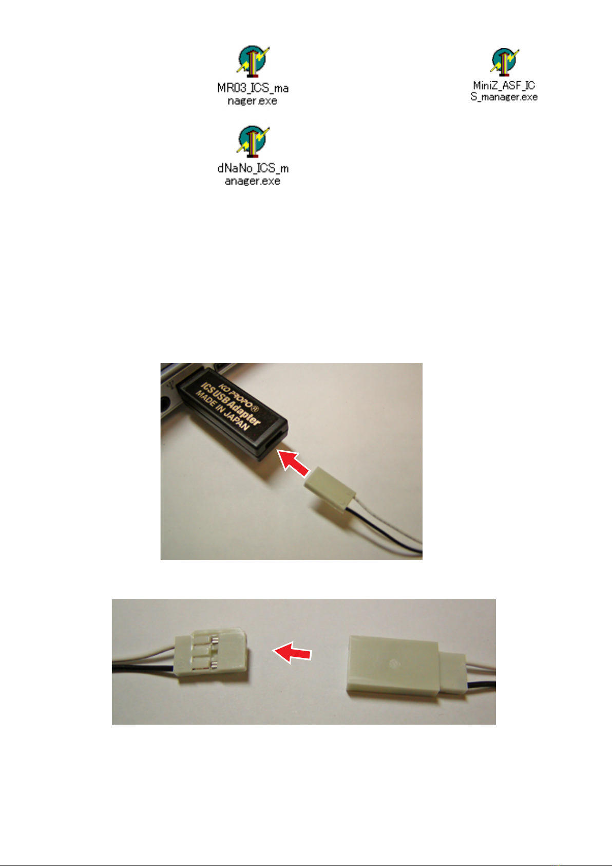
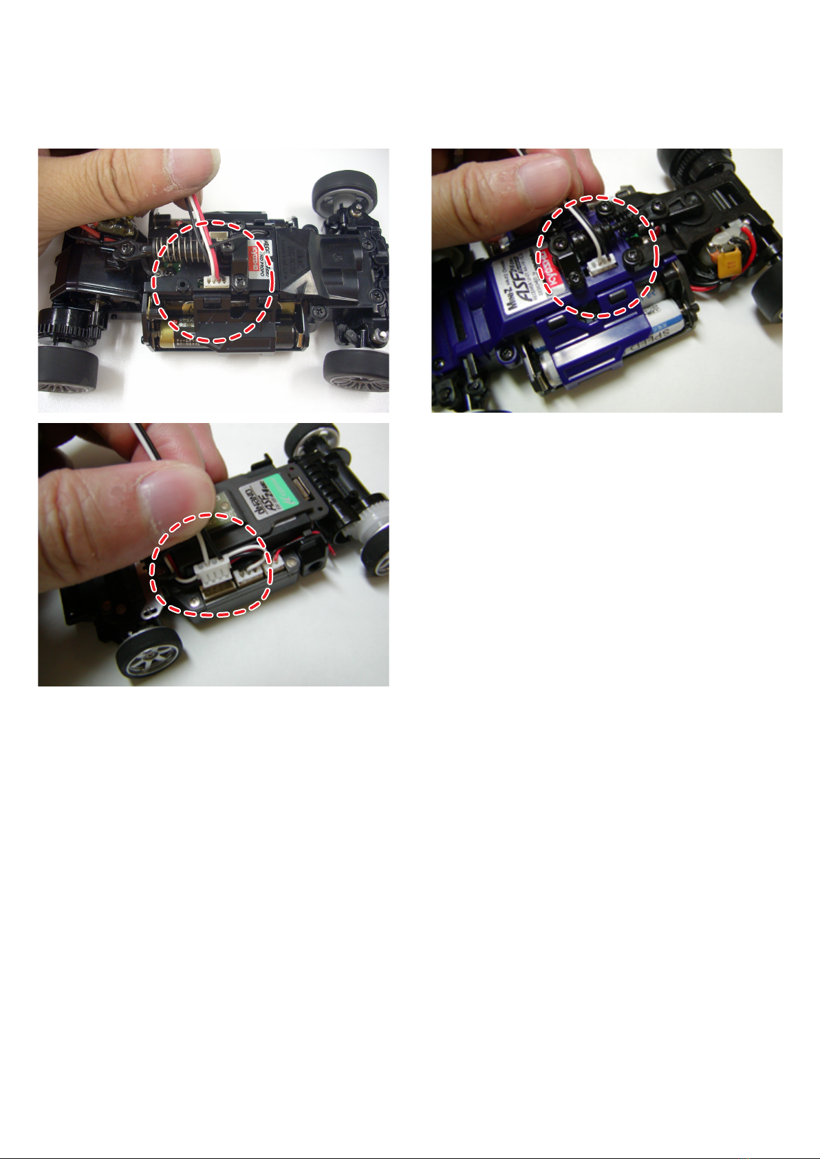
This product is used to connect Mini-Z MR-03
Series, Mini-Z ASF 2.4GHz series or dNaNo FX
series models to a personal computer, and
through a special software program it can adjust
steering and throttle settings.
*Standard settings are set at time of shipment.
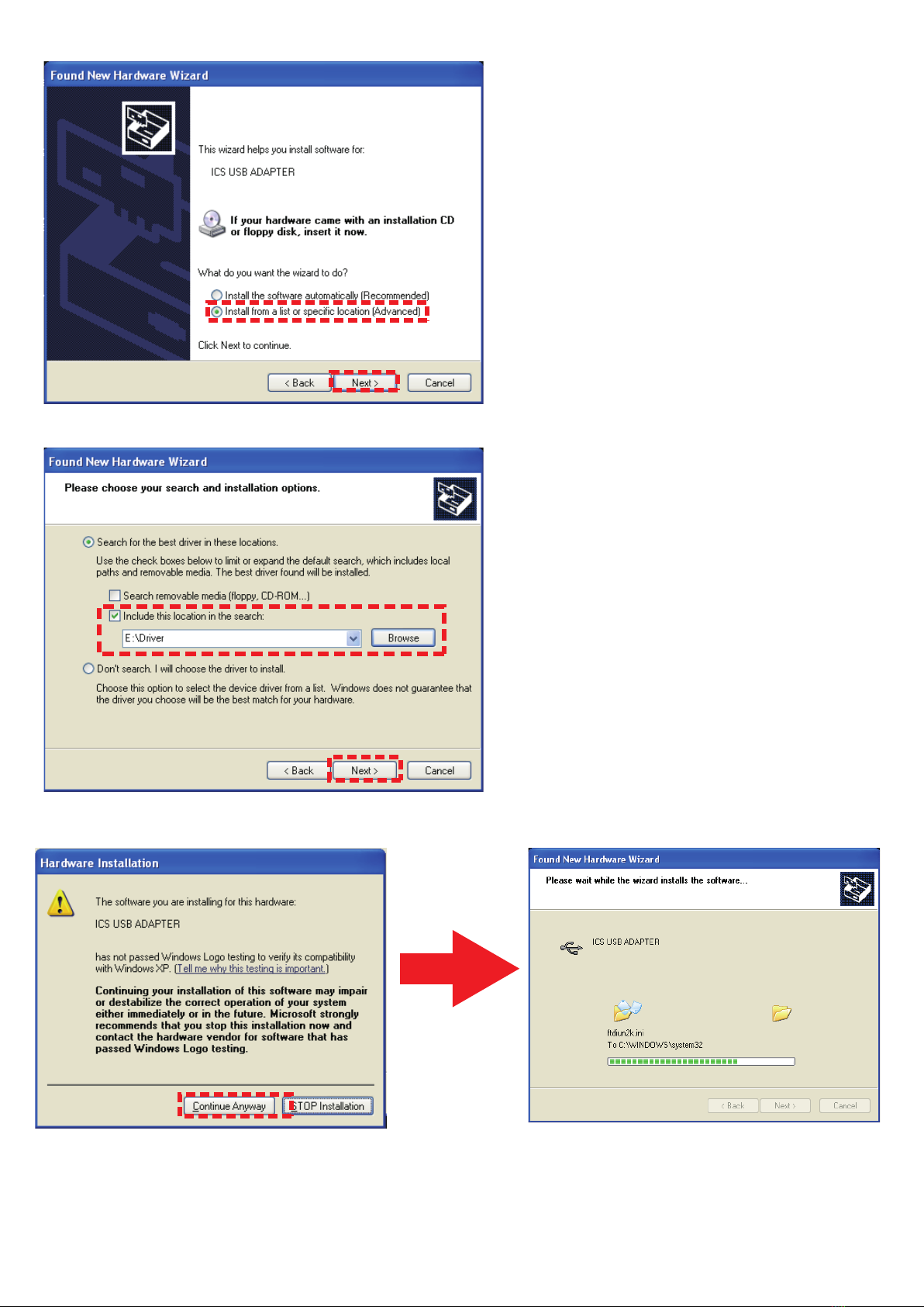
●System Requirements
・Computer with Microsoft Windows 2000 or
Windows XP and one available USB port (1.1 or
2.0).
・Windows 2000 or Windows XP (Normal function
with emulators is not guaranteed).
・CD-ROM Drive
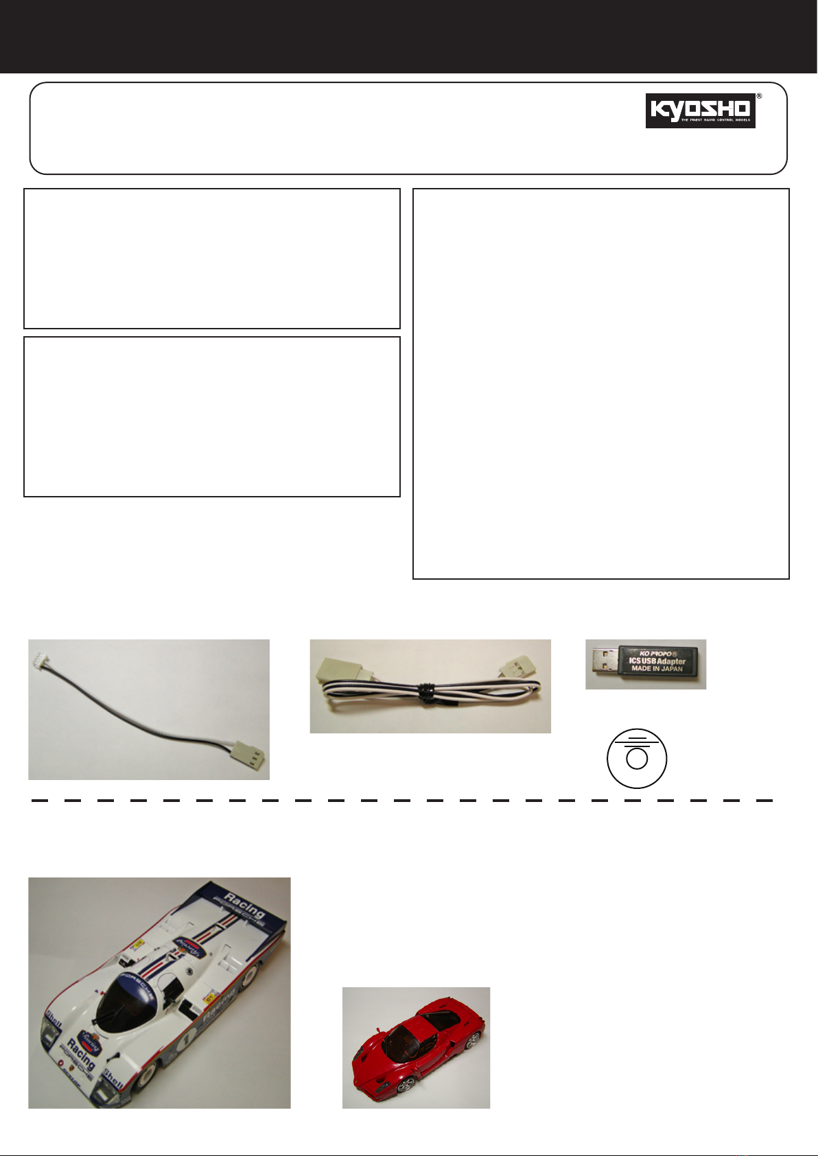
No. 82080
Instruction Manual
・Mini-Z MR-03 Series, Mini-Z ASF 2.4 GHz series or dNaNo FX series model
・ICS USB Adapter
・CD-ROM
・Extension Cable
・4-pin Cable
●Set Contents
●Required for Operation
1