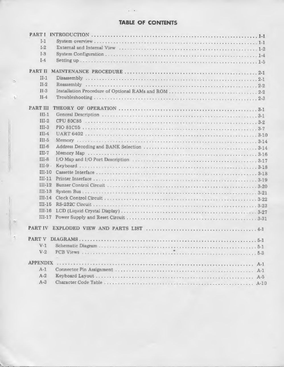
KYOTRONIC KC-85 User manual

SERVICE
MANUAL
KYOTRONIC*
KC-85
PORTABLE
COMPUTER
KYOSE!
CO.,
LTD.
OSAKA
JAPAN

TABLE
OF
CONTENTS
PARTI
INTRODUCTION
.........
:
T-1
EDI
OTe
N
Cha
kT
8
Drea
ESO
(OTN
ACR
TE
eR
OCICS
PRET:
ee
REP
Ee
PREC
Oe
Ea
TE
1-2
External
and
Internal
View
..
13
System
Configuration
.
1-4
Setting
up
PART
II
MAINTENANCE
PROCEDURE
Il-1
Disassembly
Il-2
Reassembly
-
Il-3_
Installation
Procedure
of
Optional
RAMs
and
ROM
Il-4
Troubleshooting
PART
III
THEORY
OF
OPERATION
.......
IlI-1
General
Description
.
.
IlIl-2
CPU
80C85
Ill-3
PIO
81C55
.
Ill-4
UART6402......
MUIASIP
ROTMOEY)
«5,
sip
nice
Sse
Gnvis
ie
serstoreaviavl
levee
Ill-6
Address
Decoding
and
BANK
Selection
IlIl-7_
Memory
Map
Ill-8
I/O
Map
and
I/O
Port
Description
PLD
AU
RUSY
OMIM
vince
ecrs
vis
varias
EUR
AE
Sy
acecplatd’
eve
Ug
erceNOCouaie
sos
Cay
@
HRB
ERT
ee
oo
gana
Te
al
TII-10
Cassette
Interface
.
Ill-11
Printer
Interface
..
IlI-12
Buzzer
Control
Circuit
UEEWES!
SLOT
RRS
<i
Cor
er
ark
3
pas 05e
Sra
bivratelobetutat
ie
IlI-14
Clock
Control
Circuit
MEEESED
«
FUSRe
AO
HOUMCUAEY
at
trun
ingress
og
wove
eViGe
ny
Rink
V0.8
sinc
3d
alm
oh
confuse
oc
ee
ba
eH
Fk
THl-16
LCD
(Liquid
Crystal
Display)
III-17
Power
Supply
and
Reset
Circuit
PART
V
DIAGRAMS...........
V-1
Schematic
Diagram
V-2
PCB
Views
APPENDIX
A-l
Connector
Pin
Assignment
A-2
Keyboard
Layout
A-3
Character
Code
Table

i
INTRODUCTION

I.
INTRODUCTION
In
this
section,
we
will
describe
the
system
over-
view
on
the
KYOTRONIC
85
such
as
external
and
internal
views,
system
configuration
and
set-
ting
up.
I-1
System
Overview
The
KYOTRONIC
85
isa
light-weighted
Portable
Computer
which
has
following
features:
e
Built-in
application
programs.
2-way
power
supply
by
dry
batteries
or
AC
adaptor.
e
80C85
Microprocessor
pin
and
software
com-
patible
with
intel
8085.
e
A-32K
Byte
ROM
which
contains
powerful
BASIC
interpreter.
©
Standard
16K-Byte
RAM
and
can
be
increased
up
to
32K
Bytes
easily.
Peripheral
I/O
Interface
such
as
for
printer,
RS-232C
and
cassette
recorder.
Built-in
Ni-Cd
battery
for
RAM
and
clock
func-
tion
back-up.
e
Auto
power
off
function
for
saving
the
battery
life.
I-1-1
Built-in
Apprication
Programs
BASIC:
The
principal
language
to
operate
the
computer.
TEXT:
This
function
is
a
simple
text
editor
for
creating
and
modifying
text.
TELCOM:
Telecommunication
function.
Terminal
emulation
of
file
up-load
and
down-load
features
through
RS-232C
interface.
[-1-2
2-way
Power
Supply
by
Dry
Battery
or
AC
Adaptor
The
KYOTRONIC
85
can
be
operated
by
4
dry
batteries
(Size
AA,
AM-3)
for
hand
held
carry
or
AC
adaptor
for
office
use.
Life
time
of
battery
operation
is
as
follows:
One
hour
per
day
....---ssee0%
Typical
20
days
Four
hours
per
day
.....-...+++
Typical
5
days
(Without
I/O
interface
at
normal
temperature)
I-1-3
Large
LCD
(Liquid
Crystal
Display)
Screen
The
LCD
has
240
dots
in
x-direction
and
64
dots
in
y-direction.
The
unit
size
of
the
dot
is
0.8
m/m
X
0.8
m/m.
User
is
available
to
change
view
angle
of
LCD
display
by
rotating
contrast
volume.
1-1-4
80C85
Microprocessor
80C85
is
software
compatible
with
8085
but
is
C-MOS
low
power
processor.
1-1-5
ROM
(Read
Only
Memory)
ROM
stores
application
programs
of
the
computer.
It
is
equipped
with
a
32K
ROM.
As
an
optional
feature,
extra
32K
ROM
can
be
installed.
Therefore,
by
doing
this,
capacity
of
ROM
is
ex-
tended
to
64K
and
user
can
use
them
separately
by
dividing
it
into
two
BANKs.
1-1-6
RAM
(Random
Access
Memory)
RAM
stores
BASIC
program
and
data.
Even
if
power
switch
is
turned
off,
the
contents
of
RAM
are
not
erased
because
of
recovery
by
back-
up
battery
equipped
in
the
computer.
The
com-
puter
contains
standard
16K
RAM.
As
an
optional
feature,
extra
RAM
up
to
16K
is
available
for
enhancement
by
installing
them
into
IC
sockets
on
the
MAIN
P.C.B.
Installation
procedure
for
optional
RAMs
is
shown
in
Section
II-3.
I-1-7
Peripheral
I/O
Interface
RS-232C:
Conforms
to
EIA
Standard.
Audio
Cassette
Interface:
Allows
to
use
audio
cassette
recorder
for
saving
or
loading
a
data
or
program.
Printer
Interface:
Conforms
to
Centronics
Inter-
face
Standard.
1-1-8
Built-in
Battery
for
RAM
Back-up
The
rechargeable
Ni-Cd
battery
supports
RAM
for
typical
20
days
(Standard
16K
RAM
installed).
This
battery
also
keeps
the
clock
function
when
the
power
is
off.
1-1-9
Auto
Power
Off
At
the
command-waiting
condition,
DC
power
is
automatically
cut
off
if
there
is
no
key-in
for
10
minutes.
To
re-start
the
operation,
switch
off
the
power
ON/OFF
switch
first,
then
switch
it
on
again.
The
value
of
interval
time
can
be
changed
by
software.

I-2
External
and
Internal
View
LCD
SCREEN
KEYBOARD
TOP
CASE
AC
ADAPTER
JACK
BOTTOM
CASE
CONTRAST
VR
POWER
SWITCH
Figure
I-1
Front
View
RESET
PRINTER
SWITCH
CONNECTOR
RS-232C
CASSETTE
RECORDER
CONNECTOR CONNECTOR
Figure
I-2
Rear
View

RELAY
FOR
CASSETTE
INTERFACE
Ni-Cd
BATTERY
oc/DC
cey
CONVERTER
X'TAL
FOR
SYSTEM
CLOCK
X'TAL
FOR
CLOCK
OPTIONAL
STANDARD
STANDARD
RAM
RAM
ROM
Figure
I-3
Internal
View
(1)
LCD
PCB
(KEY
BOARD)
SUPPORT
(KEY
BOARD)
PCB
Figure
I-4
Internal
View
(2)

I-3
System
Configuration
The
KYOTRONIC
85
can
be
connected
to
following
peripherals.
PRINTER
INTERFACE
CASSETTE
INTERFACE
RS-232C
INTERFACE
CASSETTE
TYPEWRITER
SYSTEM
BUS
INTERFACE
EXTERNAL
I/O
DEVICE
Figure
I-5
System
Configuration

1-4
Setting
up
Install
four
AM-3
type
batteries
or
connect
the
AC
adaptor.
After
installing
the
operational
batteries
or
connecting
AC
adaptor,
turn
on
MEMORY
POWER
Switch
on
the
bottom
case.
If
the
MEMORY
POWER
Switch
is
off,
the
computer
does
not
operate
even
if
the
power
switch
is
on.
Ni-Cd
battery
inside
the
case
is
used
to
protect
RAM.
Then,
turn
on
the
POWER
Switch.
Following
MENU
will
appear
on
the
LCD
display.
Adjust
the
view
angle
by
adjusting
the
CON-
TRAST
volume
so
that
you
can
set
it
at
the
best
position
to
operate
the
computer.
Figure
I-5
Initial
Screen

II.
MAINTENANCE
PROCEDURE

Il.
MAINTENANCE
PROCEDURE
This
section
provides
information
about
regular
maintenance
for
the
KYOTRONIC
85
such
as
II-1_
Disassembly
Upper
and
lower
Case
Removal:
1.
Disconnect
the
cables
from
the
unit.
Taking
care
not
to
scratch
any
key
top,
turn
the
unit
over
and
remove
the
four
screws
4
from
the
upper
and
lower
cases.
Remove
the
upper
case;
it
opens
to
the
right
side.
Please
note
that
the
upper
and
lower
cases
are
secured
by
snaps.
Also,
do
not
apply
too
much
force
when
pulling
open;
the
LCD
and
key-
board
connectors
are
attached.
3.
Remove
the
LCD,
key
board
and
LED
con-
nectors
from
the
MAIN
P.C.B.
i)
LCD
connector
LED
connector
disassembly,
troubleshooting
chart
and
optional
ROM
and
RAM
installation.
K/B
P.C.B.
Removal:
1.
Remove
the
five
screws
8)
and
then
remove
the
K/B
P.C.B.
and
K/B
supports.
LCD
P.C.B.
Removal:
1.
Remove
the
buzzer
connector
from
the
LCD
P.C.B..
2.
Remove
the
four
screws
(
the
LCD
P.C.B.
and
then
remove
MAIN
P.C.B.
Removal:
1.
Remove
the
seven
screws
0).
2,
Remove
the
MAIN
P.C.B.
upward,
taking
care
when
removing
the
RESET
switch
and
battery
contact
spring.
Buzzer
connector
Key
board
connectors
Figure
II-1
Disassembly
II-2
Reassembly
MAIN
P.C.B.
Reassembly:
1.
Align
the
screw
positions
of
the
lower
case
with
the
MAIN
P.C.B.
Gently
insert
the
MAIN
P.C.B.
from
the
rear
and
place
the
reset
switch
knob
in
the
proper
notch.
2.
Secure
the
battery
contact
spring.
3.
Attach
the
MAIN
P.C.B.
to
the
lower
case
by
using
the
seven
M3
X
8
screws.
LCD
P.C.B.
Reassembly:
1.
Attach
the
LCD
P.C.B.
to
the
upper
case
by
using
the
four
M3
X
3
screws.
2.
Insert
the
buzzer
connector
in
the
LCD
P.C.B.
K/B
P.C.B.
Reassembly:
1.
Align
the
two
K/B
supports
with
the
holes
in
the
P.C.B.
and
attach
them
so
that
they
fit
to
the
P.C.B.
edge.
2.
Align
the
K/B
supports
and
K/B
P.C.B.
holes
with
the
upper
case
screws.
3.
Attach
the
K/B
supports
and
K/B
P.C.B.
to
the
upper
case
by
using
the
five
M3
X
8
screws.

CASE
Reassembly:
1.
Position
the
upper
case
to
the
right
side
of
the
lower
case,
taking
care
not
to
scratch.the
key
top,
2.
Attach
the
LCD
K/B
and
LED
connectors
to
the
MAIN
P.C.B.
3.
Place
the
upper
case
over
the
lower
case,
taking
II-3
Installation
of
Optional
RAMs
and
ROM
1.
Installation
of
Optional
RAMs:
Open
the
Top
and
Bottom
Case
of
the
com-
puter
(refer
to
Part
II-1
Disassembly
and
Il-2
Reassembly).
On
the
MAIN
P.C.
Board,
you
can
find
two
IC
sockets
marked
“OPTION
RAM”.
You
must
install
the
first
8K-RAM
on
care
that
the
cable
is
not
pulled
out
of
place,
Align
the
upper
and
lower
cases
so
that
the
tabs
fit
well.
Turn
the
cases
over,
and
secure
them
together
by
using
the
four
M3
X
8
screws.
the
IC
socket
marked
“OPTION
RAM
#2”.
Prior
to
inserting
the
RAMs,
make
sure
that
all
the
pins
of
the
RAM
are
correctly
aligned
against
the
socket
pins.
Figure
II-2
Installation
of
Optional
RAM
2.
Installation
of
Optional
ROM:
Using
the
coin,
remove
the
ROM
Cover
on
the
Buttom
Case.
You
will
find
an
IC
socket
with
a
plastic
housing.
Insert
optional
ROM
into
this
socket.
On
the
P.C,
Board,
at’
the
four
IC
Socket
for
Optional
ee
cornérs
of
the
IC
socket,
you
will
find
the
number
of
pins,
such
as
1,
14,
and
28.
Pay
attention
that
pin-1
of
the
ROM
is
cor-
rectly
aligned
against
pin-1
of
the
IC
socket.
Figure
II-3
Installation
of
Optional
ROM

II-4
Troubleshooting
This
section
shows
you
how
to
go
about
solving
a
problem
or
malfunction
that
has
been
identified.
All
you
have
to
do,
is
find
the
problem
in
the
Troubleshooting
Guide
and
refer
to
the
section
indicated
by
the
number.
Each
section
then
identifies
the
components
associated
with
the
circuit
in
question
and
provides
remedial
instruc-
tions.
After
completing
any
repairs,
you
should
re-check
each
functional
item
according
to
the
CHECK
LIST.
You
can
make
use
of
the
CHECK
LIST
even
if
the
location
and
condition
of
the
mal-
function
are
not
readily
identified.
Note:
The
arrow
mark
(
—
)
in
this
Troubleshooting
Chart
shows
each
check
point
number
of
the
Check
Point
Location
Chart
(page
2-15).

TROUBLESHOOTING
GUIDE
START
Doesn't
work
at
all?
LCD
doesn’t
function?
YES
Keys
don’t
function?
YES
Buzzer
doesn’t
function?
YES
Clock
doesn’t
function?
YES
RESET
doesn’t
function?
Memory
protection
doesn’t
function?
TO
NEXT
PAGE
2-4

Printer
Interface
doesn’t
function?
Cassette
interface
doesn’t
function?
RS-232C
interface
doesn’t
function?
All
functions
check
OK?

1.
Doesn’t
work
at
all
Check
the
power
©
Check
to
be
sure
that
the
batteries
are
in
and
that
the
AC
adaptor
is
connected.
@
\s
the
memory
power
switch
ON?
©
Is
the
power
switch
ON?
Check
the
DC/DC
converter
circuit.
>
1-1
(VL)
©
|s
3,6—8V
applied
to
pin
4
of
the
converter
transformer?
(If
not,
check
C2
~
C8,
battery
contacts
and
adapter
jack.)
©
Check
all
output
voltages.
a)
VDD...
+5V
(if
not,
check
D7,
C15
and
D6)
>
1-2
(VDD)
b)
VEE
—5V
(if
not,
check
D4,
C13
and
RD5)
—
1:3
(VEE)
c)
VB.
+5V
(if
not,
check
T15
and
T16)
>
1-4
(VB)
@
\s
T6
oscillating?
—
1-5
(76)
(If
not,
check
T7, T8,
C11,
R19,
R18,
R20
and
T6.)
Check
the
RESET
and
RAM
RST
signal.
©
Is
RESET
signal
high
level
(+2.2V
—5.3V)?
If
not,
check
T10,
T11,
T12,
T9
RESET
signal.
>
1-6
(M19
Pin
36
RESET)
@
Is
RAM
RST
signal
low
level
(0.8V
—0.3V)?
If
not,
check
T10, T11,
712,
T9
and
RAM
RST
signal.
Check
the
logic
circuit.
@
Check
the
CPU
clock
frequency.
(X1
terminal
=
4.9152
MHz;
CLK
terminal
=
2.4576
MHz)
(If
not,
check
X2
and
M19.)
@
Try
replacing
the
LCD
unit.
®@
Check
all
ICs,
—>
1-7
(M19
Pin
1)

2.
LCD
doesn’t
function
NO
No
display
at
all
YES
Check
source
voltage
(VDD,
VEE,
VB).
Refer
to
(1)
“Doesn't
work
at
all’.
Check
the
RESET
signal.
Refer
to
(6)
“RESET
doesn’t
function’.
Check
the
LCD
waveform.
(If
abnormal,
check
the
LCD
power
supply
operation
amplifier.)
Check
the
interface
circuitry.
(Check
all
IC’s
connected
to
the
bus
line,
M17
and
M20.)
Check
if
connector
is
correctly
connected.)
Check
LCD
drivers
(on
LCD
PCB)
HD44102
and
HD44103.
(Or
replace
the
LCD
unit.)

3.
Keys
don’t
function
Check
if
keyboard
connector
is
correctly
connected.
Check
the
key
scan
signal.
Is
scan
signal
present
at
M25
PAO
—
PA7
and
PB1?
(If
not,
check
if
pulses
are
emitted
from
the
TP
terminal
(pin
10)
of
M18
and
M285
at
4
msec
intervals.)
—>
3-1
(M25
Pin
21
to
30)
—>
3-2
(M18
Pin
10)
—>
3-3
(M19
Pin
7)
—>
3-4
(CN7)
4.
Buzzer
doesn’t
function
Check
connector
connections.
©
Check
if
LCD
connector
is
correctly
connected.
©
Check
if
buzzer
connector
on
LCD
PCB
is
correctly
connected.
—>
4-1
(T19)
—>
4-2
(M26
Pin
13)
—>
4-3
(M34
Pin
4)
—>
4-4
(M25
Pin
34)
—>
4-5
(M25
Pin
6)
Check
the
buzzer.
2-8

5.
Clock
doesn’t
function
Check
the
power
supply
voltage.
When
power
ON:
+5V
@
When
power
OFF:
2.0
—
4.0V
(If
not
normal,
check
power
supply
circuit.)
—>
5-1
(M18
Pin
14,
VB)
ae
Check
that
a
250-Hz
pulse
is
output
from
TP
signal.
—
=F
Check
clock-setting
1Cs
(M14
and
M25)
and
ignal.
6.
RESET
doesn’t
function
4
I
Check
RESET
circuit.
(Check
T11,
T10,
T9,
T12,
DB,
D9
and
C17.)
—>
5-3
(M18
Pin
10,
TP)
Check
oscillation
frequency
(F=32.768
kHz).
.
(If
not
normal,
check
X1,
C62,
C63
and
M18.)
—>
5-2
(M18
Pin
12)
Check
all
ICs
which
have
RESET”
and
RESET
signals.
(Check
M19, M25,
M22,
M14, M34,
and
also
check
LCD
unit
and
RAM.)

7.
Memory
protection
doesn’t
function
©
Check
power
supply
voltage.
@
When
power
ON:
VB
=
+5V
(if
not,
check
converter
circuit)
—>
7-1
(VB)
@
When
power
OFF:
VB
=
2,0
—
4,0V
(if
not,
check
Ni-Cad
battery,
D2
and
D18)
Check
to
be
sure
that
there
is
not
deviation
in
the
timing
of
the
signal
and
that
the
level
changes
symmetrically,
when
the
RAM
RST
add
RESET
are.
—>
7-2
(T12,
RAM
RST)
switched
ON/OFF.
Check
CMOS
RAM.
8.
Printer
interface
doesn’t
function
->
8-1
(T18,
STROBE)
>
8-2
(M14
Pin
2)
Check
th
data
signals.
Check
M25,
M38
and
M32.
Check
the
connector
and
printer
cable,
>
8-3
(M25,
38,
32)

9.
Cassette
interface
doesn't
function
Check
TXC
signals.
{1s
a
modulated
waveform
output
to
pin
5
of
the
cassette
connector
during
program
(DATA)
save?
(If
not,
check
M34, M19,
C30
and
C31.)
—>
9-1
(CN2,
TXC)
Check
RXC
signals.
|s
a
digital
waveform
input
to
the
SID
terminal
of
the
CPU
during
program
(DATA)
load?
(If
not,
check
D11,
D12, 013,
M37,
M34
and
M19.)
—>
9-2
(M19
Pin
5,
SID)
Check
the
cassette
connector
and
cassette
cable.
Table of contents