©Copyright L-1 Standards and Technol-
ogy, Inc. 2015
No part of this manual may be repro-
duced in any form or by any means
(including electronic storage and retrieval
or translation into a foreign language)
without prior agreement and written con-
sent from L-1 Standards and Technology,
Inc. as governed by United States and
international copyright laws.
Warranty
The material contained in this document
is provided “as is,” and is subject to being
changed without notice. Further, to the
maximum extent permitted by applicable
law, L-1 Standards and Technology, Inc.
disclaims all warranties, either express
or implied, with regard to this manual
and any information contained herein,
including but not limited to the implied
warranties of merchantability and tness
for a particular purpose. L-1 shall not be
liable for errors or for any direct, indirect,
incidental, consequential, or other dam-
ages in connection with the furnishings,
use, or performance of this document or
of any information contained herein.
Manual Part Number
TIA-MANUAL-REV3
Edition
First Edition, November 2015
L-1 Standards and Technology, Inc.
209 High Street
New Windsor, MD 21776-0729
USA
+1 410-635-3300 Phone
+1 410-635-3200 FAX
www.L-1.biz
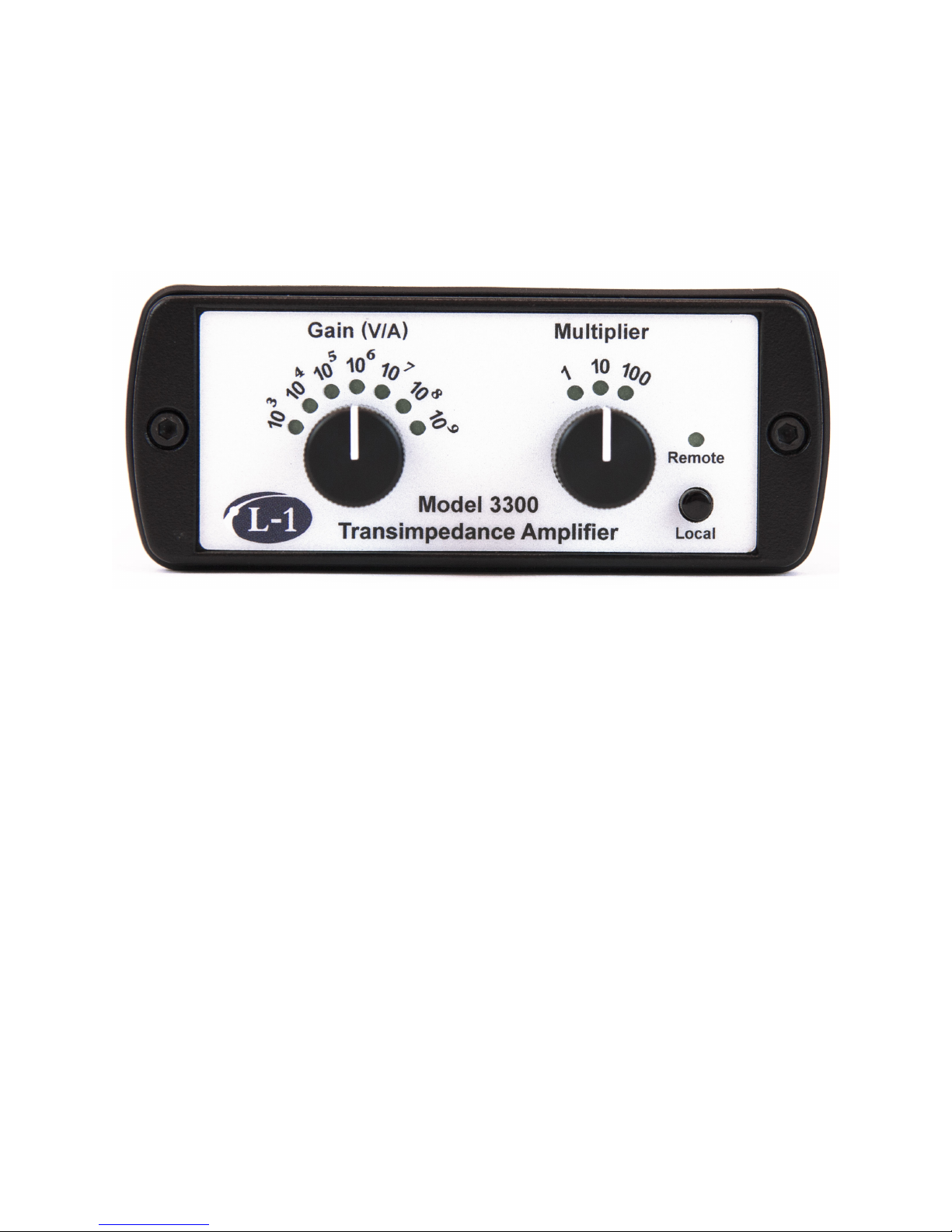
Model 3300 Transimpedance Amplier (TIA) User Manual
Rev3