Trinity Amps Trinity Tweed Amp User manual

The Trinity Tweed
Amp Builder's Guide
USAGE STRICTLY RESERVED FOR TRINITY AMPS CUSTOMERS ONLY
DO NOT DISTRIBUTE
Version 3.2
Parts © Trinity Amps 2005 - 2018
www.trinityamps.com

Version 3.2 Page: 2

Version 3.2 Page: 3
Table of Contents
Introduction..........................................................................................................................................5
Acknowledgements..............................................................................................................................5
WARNING ..........................................................................................................................................6
Please Read this Information Carefully .............................................................6
Version Control....................................................................................................................................7
Guitar Amplifier Basics.......................................................................................................................8
Fender and Marshall tone controls..............................................................................9
Interactive Volume Controls –Fender Tweed Amps .................................................. 12
Distortion .............................................................................................................. 14
Introduction to Vacuum Tubes and Common Terms .................................................................17
Input Jack Theory ..............................................................................................................................20
Circuit Description.............................................................................................................................21
Original Circuit with outlined stagesTweed Specifications..........................................................22
Fender amps own the blues … ........................................................................................................24
Building an Amp ................................................................................................................................26
Introduction........................................................................................................... 26
Switches and wire ................................................................................................... 26
Physical layout........................................................................................................ 26
Grounding ............................................................................................................. 26
Insulated jacks ........................................................................................................ 27
Minimizing transformer interference......................................................................... 27
Wiring ................................................................................................................... 27
Assembling the amp ..........................................................................................................................27
Before You Begin ................................................................................................... 27
Tools..................................................................................................................... 27
Soldering................................................................................................................ 28
Tube Pin Numbering .............................................................................................. 28
Assembly Steps Summary ........................................................................................ 29
Mounting Hardware Locations................................................................................. 30
Install Hardware .................................................................................................................................30
Wiring ................................................................................................................... 32
Install Power Transformer................................................................................................................34
Wiring the Tweed Rectifier Socket ................................................................35
Trinity Tweed Grounding Scheme................................................................. 35
Mains Power Connection ............................................................................36
Testing the Power Transformer................................................................................ 40
Install the Output Transformer - Output Jacks .......................................................... 40
Impedance Switch................................................................................................... 41
Assemble the Eyelet Board...............................................................................................................43
Connecting the Board ................................................................................45
Connect Board to Potentiometers .................................................................45
Input Jacks ..........................................................................................................................................47
Final checkout.....................................................................................................................................48
Working Inside A Tube Amplifier Safely................................................................... 50
Unplug ...................................................................................................50
Sit.......................................................................................................... 50

Version 3.2 Page: 4
Drain .....................................................................................................50
Test .......................................................................................................50
Close......................................................................................................50
Making a Voltage Measurement................................................................................ 51
Discharging the Power Supply.................................................................................. 51
General Amplifier Operation ...........................................................................................................53
Some DO NOTS.................................................................................................... 53
Trinity Tweed Voltage Chart............................................................................................................54
WARNING ........................................................................................................................................55
Please Read this Information Carefully ...........................................................55
Troubleshooting .................................................................................................................................56
Hum...................................................................................................................... 56
Volume Test .......................................................................................................... 56
Faulty tube............................................................................................................. 56
Severely unmatched output tubes in a push pull amplifier ........................................... 56
Faulty power supply filter caps ................................................................................. 57
Faulty bias supply in fixed bias amplifiers .................................................................. 57
Unbalanced or not-ground-referenced filament winding ............................................. 57
Defective input jack ................................................................................................ 58
Poor AC grounding................................................................................................. 58
Induced hum.......................................................................................................... 58
Poor internal wire routing........................................................................................ 58
Poor AC Chassis Ground at Power Transformer ....................................................... 58
Defective internal grounding.................................................................................... 59
Hiss....................................................................................................................... 59
Metal Film Resistor Substitutions ............................................................................. 59
Squealing/Feedback................................................................................................ 59
Radio Interference .................................................................................................. 60
Scratchy Sounds on Potentiometer(s)........................................................................ 60
Amp Buzz or Rattle When Installed in Cabinet.......................................................... 60
Tone Tweaking...................................................................................................................................62
More Tips for fine tuning your amp.......................................................................... 63
Running 6L6 Output Tubes .............................................................................................................64
Tube Substitutions .............................................................................................................................67
How to read Resistor Color Codes .................................................................................................68
How to read Capacitor Codes..........................................................................................................69
FAQ .....................................................................................................................................................71
TWEED Bill of Materials (BOM) ...................................................................................................73
Trinity Amps Schematics and Layouts............................................................................................74

Version 3.2 Page: 5
Introduction
This guide has been prepared for builders of Trinity Amps Kits. It is always being improved
Accordingly, content and specifications are subject to change without notice.
We do try to make it as accurate as possible, but it is sometimes hard to keep up with the
changes. Therefore, if you do find an error, please let us know about it and we will correct it.
Suggestions are welcome so if you have one, please get in touch with us.
Sources of help.
Forums: Please use the various forums to get help. They are an excellent resource and can be
found at trinityamps.com Fender forum.
The Fender Amp Field Guide is a terrific resource for all amps Fender
Email: We can’t help with every problem but if you can not get your problem resolved, email
us and we’ll do our best to help.
Phone Call: If your problem can’t be solved, email for a phone appointment.
Acknowledgements
Much of the content in this document is original. Rather than reinvent content, some parts
are based on content from other excellent sources and are hereby acknowledged.
R.G. Keen’s site www.geofex.com - Tube Amp FAQ, Tube Amp Debugging
AX84.com site www.AX84.com - Gary Anwyl's P1 construction guide version 1.0
GM Arts website http://users.chariot.net.au/~gmarts/index.html - Guitar Amp Basics
Aron from diystompboxes.com
Parts © Trinity Amps 2005. No part of this document may be copied or reprinted without
written permission of Trinity Amps or contributing authors listed above.

Version 3.2 Page: 6
WARNING
Please Read this Information Carefully
The projects described in these pages utilize POTENTIALLY FATAL HIGH
VOLTAGES. If you are in any way unfamiliar with high voltage circuits or are
uncomfortable working around high voltages, PLEASE DO NOT RISK YOUR LIFE
BY BUILDING THEM.Seek help from a competent technician before building any
unfamiliar electronics circuit. While efforts are made to ensure accuracy of these circuits, no
guarantee is provided, of any kind!
USE AT YOUR OWN RISK:
TRINITY AMPS EXPRESSLY DISCLAIM ALL
LIABILITY FOR INJURY OR PROPERTY DAMAGE RESULTING FROM THIS
INFORMATION! ALL INFORMATION IS PROVIDED 'AS-IS' AND WITHOUT
WARRANTY OF ANY KIND.
REMEMBER: NEVER OPERATE YOUR AMP WITHOUT A LOAD. YOU WILL
RUIN YOUR OUTPUT TRASNFORMER!

Version 3.2 Page: 7
Version Control
Version
Date
Change
2.0
1 Oct 12
New issue for New board & layout
2.01
6 Oct 12
Added 240V Transformer Wiring layout
2.1
16 Jul 13
Updated BOM; Note on transformer mounting added.
2.2
8Mar14
Note added to test PT AC voltages before proceeding.
2.3
9 Jun 14
Clarified start up procedure with numbered steps.
2.4
6Aug14
Added HI Capacity PT and 8/4 Ohm OT
2.5
28Jan15
BOM Updated, Added Optional PI resistor; clarifications mad;
input jack theory added
2.7
15Jan16
Updated BOM to reflect IEC socket & Impedance switch
2.8
6Feb16
Updated for IEC socket wiring
2.9
8Mar16
Updated for IEC and Impedance Switch additions.
2.91
28AJul16
Updated layout for Mods section to show correct orientation of
input jacks
2.92
23Apr17
Updated BOM
2.93
19Dec17
Updated eyelet board layout ; added power transformer testing
section
2.94
4Mar18
Updated ‘Running 6L6 Output Tubes’ section
3.0
19May18
Updated for new Power Transformer 9114-2-EX connections
3.1
14Jul18
Updated Running 6L6 Output Tubes
3.2
25Aug18
Updated 240V layout picture

Version 3.2 Page: 8
Guitar Amplifier Basics
Electric guitarists can be fairly criticized for their reluctance to change to new ideas and
technologies; however, there is no doubt that a classic 1950’s guitar and tube amplifier in
good condition still sounds great in modern recordings. This is a testament to good design
from the start. What has improved today is consistency, and the cost benefits of production
line manuFacture. This is offset by the rarity of good guitar wood (it makes a huge
difference, even on an electric guitar), increased labour costs for both guitars and
amplification equipment, and the availability of good and consistent quality tubes.
There is also an element of nostalgia, with memories of many of the great players of years
gone by, and the desire to use the same types of instruments and equipment to recapture the
magic. Vintage instruments and equipment have also become valuable collectors items (some
with very inflated prices) which adds further to the desirability of older tools of the trade.
There has been a recent trend by many companies to re-market their original instruments
and equipment; new guitars can even be bought now ‘pre-aged’!
This desire for vintage equipment is also related to guitarists’ reluctance to part with tube
amplification, and there are many reasons why tube and solid state amplifiers behave
differently. Quite simply, if players prefer the sound of tubes, they will continue to buy and
use them. Here are some fundamentals.
Input Impedance
Typically 1M, 500K minimum (humbucking pickup guitars have volume
pots up to 500K, single coil pickup guitars typically of 250K) .
Tone Controls
Magnetic guitar pickups are inductive, and require compensation, although this
opportunity is also used for tone enhancement, not just correction. Without compensation,
they have a strong low middle emphasis and little high frequency response - overall a very
muddy and muFfled sound. This is why typical hi-fi Baxandall treble & bass controls are
unsuitable.
To hear the natural sound of a pickup, use a typical guitar amp with the middle set to full,
and bass and treble on 0. This is actually sets a flat response in the amp (see below). Expect
to hear a muFfled and muddy sound. And that's the whole point of these tone controls
providing compensation for the natural sound of a pickup - the middle control simply
boosts the pickup's normal ‘middley’ sound. The treble and bass controls do the opposite -
they boost higher and lower frequency levels, leaving a notch in-between for middle cut (see
the Fender/Marshall comparison below). So with typical settings of a bit of bass, middle and
treble, the overall tone equalization complements the natural pickup sound for a balanced
response of lows, mids and highs.

Version 3.2 Page: 9
Full middle boost with no bass or treble actually gives a near-flat frequency response,
allowing you to hear the natural sound of your pickups.
Fender and Marshall tone controls
Here are circuit diagrams of typical Fender and Marshall tone controls. They both meet the
criteria of compensating for pickups' low-middle emphasis, as well as providing a useful
range of tone adjustment.
The Fender and Marshall circuits are each tailored to suit their own styles, which are quite
different. Although a generalization, Fender's market and consequently the power output
stage are geared towards provided clean and chunky tones at clean and early-overdrive
levels. Marshall amps are best at low-middley and crunchy rock tones, played at medium to
high overdrive levels.
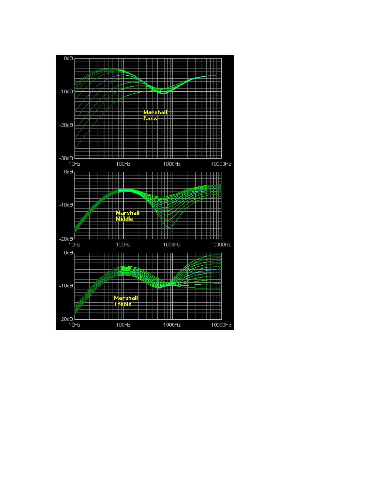
Here is a simple comparison of Marshall and Fender response with what might loosely be
called 'typical settings' of Bass on 3, Middle on 4, and Treble on 6. The most obvious
difference is that the Marshall lets more level through, and their tone controls have less
range of adjustment. The higher level means that by using the same number of preamp tube
stages, a Marshall can overdrive the output stage more.

Version 3.2 Page: 10
Bearing in mind that 6-string guitar notes don't go below 80Hz, and typical guitar speakers
cut above about 5KHz, these responses are similar. Both have a middle dip that is primarily
compensation for typical pickups' middle emphasis, rather than an obvious dip in middle
response. The Marshall circuit has this cut about an octave higher than the Fender, leaving
the low mids and bass intact for that full Marshall sound. On the other hand, Fender's tone
controls allow high-mids to pass with the treble response, and add little bass boost for the
sparkling and tight sounds they're famous for.
Here are charts each of the Fender controls. In all cases, the other two controls are left at 5.
For example, the treble chart shows he effect of varying Treble from 0 to 10, with Bass and
Middle both at 5. Notice that all controls have a wide range of adjustment, and that the bass
control has most effect from 0 to about 3. Anyone's who has used a Fender will know this,
and this control could easily be replaced by a control with a stronger logarithmic taper to
smooth this out without changing the range of available tones.

Version 3.2 Page: 11
The Fender circuit also has the unusual side effect that if all controls are set to 0, then no
sound is produced at all. The Marshall design avoids this, but the tone with all controls set
to 0 is not something you'd be likely to use anyway.
Here are the same charts for Marshall tone controls. As mentioned already, the main points
to note are the smaller range of adjustment, the higher frequency for the middle cut control,
and the higher overall signal level. The smaller adjustment range and higher level are both
caused by the use of the 33K resistor in place of Fender's 100K. The also gives the tone
stack a lower input impedance, requiring it to be fed from a lower output impedance
(cathode follower) preamp tube stage.
Version 3.2 Page: 12
Tube power amplifiers often provide an additional presence control (which reduces negative
feedback in the power amplifier section) to provide a small amount of boost at frequencies
above the treble control.
Interactive Volume Controls –Fender Tweed Amps
The Tweed has what’s referred to as “interactive volume controls”. This is also a
characteristic of the Tweed Bassman, Twin, Super, Bandmaster etc.
Version 3.2 Page: 13
In these amps, there are two volume
controls each controlling one stage of a
12AY7 tube. They are very simple and
economical circuits, only 5 parts per circuit.
Each output comes from the volume
control and passes through an “isolation”
resistor –a resistor placed in the circuit to
isolate the two volumes from each other,
and at the same time to mix them for the
next single input tube stage.
The “feature” is that the isolation resistors
values (270K) do not isolate the stages
from each other enough –one stage can
still “see” the grid load resistance from the
other. It appears to the channel you are
plugged into, that there is another resistor
in the circuit formed by the other unused
volume control and its isolation resistor.
The real “magic” of it all is probably one of the absolute best “lessons” you can learn about
vacuum tubes. You would guess that the best and loudest tone would be with the highest
resistance, with the unused pot turned all the way up, but that isn’t so. It is somewhere near
5 or 6 (on old amps, a new amp may have different pot tapers and it could appear at
different points.)
When you are turning the unused volume control you are “fine tuning” the grid load resistor
to the next stage of the amp. An optimum (best sounding) value is not all the way up, but
somewhere near the middle –the lesson? Tubes are NOT linear or mathematical devices –
they do not respond to exact mathematical figures and have “hills and valleys” in their
response –maximum performance can not be calculated directly –you have to hear it and
you have to be aware that the “truth” may not be at some exact calculated place, but at
some far more imprecise figure.
The Tweed Deluxe is unique in that the volume controls are not voltage dividers and
work by loading down the signal from the plates of the pre-amp tube. Because of this, you
get the maximum mids in the channel you are plugged into when the other volume control
is at it's mid position.. Max midrange scoop occurs when the other control is turned to full.
Set one channel (say Normal one) to max and the other (Bright) to mid position. When you
select the Bright channel, you should get nice clean tones and when you select the Normal
channel, you will get nicely distorted tones.
The clean tones work because you are not overdriving the bright channel and you are
scooping the midrange. On the Normal channel, you get the nice lead tones because you are
overdriving the output stage and boosting the mids.

Version 3.2 Page: 14
So, each of the Tweed volume controls affects your tone to a noticeable degree by creating a
hidden voicing control allowing the player to sculpt the tone in a way that no other regular
multi-band tone controls will permit. The effect is somewhat like scooping out the mid-
range and extending the bass and treble frequencies as you turn up the adjacent volume
control. In other words, the Normal volume interacts with the Bright and vice versa. This
allows the player to control the midrange of the channel used by turning the volume of the
channel not being used.
Maximum midrange occurs when the volume control of the unused channel is set about half
up (about 5). Maximum midrange scoop occurs when the volume control of the unused
channel is almost all the way up. When plugged into the bright channel with the volume
about half up and then turning the normal channel almost all the way up (around 10) will
give a cleaner tone.
Distortion
The overdriven sound of a tube power amplifier is highly desirable, with many different
output stage designs to produce the variety of trademark sounds heard on modern
recordings. The only problem is that a tube power amplifier is only capable of producing
this sound at one volume (usually, fairly loud!).
There are probably 3 distinctly identifiable types of tube power amplifiers used:
Leo Fender's classic early designs used 6V6 tubes, and later, the higher powered 6L6's. This
gave a characteristic full and punchy sound, suitable for many styles of the day, and later.
Steel and country players like the chime-like clean sounds, and blues players were quick to
discover the classic way it breaks up when pushed hard. At really high overdrive, though, the
sound becomes quite dirty, with bass in particular sounding flabby.
Marshall designs started as Fender copies, but soon switched to EL34 output tubes, possibly
for local supply reasons. Anyway, the rest is history. These tubes exhibit a softer overdrive
transition, and maintain clarity even at high overdrive levels. They also have a limited middle
response, giving rise to the famous Marshall crunch sound. The lower powered EL84 tubes
have similar characteristics.
Vox AC30 (and the more popular top boost model) uses a Class AB power amplifier design,
with the tubes biased ‘hot’, so while this operates in class A at lower levels, it is a class AB
design. There's no negative feedback in the power amp either, so this gives a different
sound, often described as a sweeter overdrive. Listen to Brian May's sounds for plenty of
good examples.
The Fender and Marshall designs use class AB for their output designs, biased with the
tubes almost off with no signal. This is more efficient (more watts per tube), and better for
tube life. When you play, tubes take turns handling each half of the signal. This leads to
some (unwanted) distortion as the tubes cross over. Class A designs are rare in medium to
high power guitar amps, but true class A has the tubes operating at half power, with no
signal applied. When you play, the tube fluctuates between full and no power, so there is no
switching to add unwanted distortion. This is a very superficial explanation; please read
elsewhere on the Internet for more detailed descriptions.
Wide Dynamic Range
A plucked guitar string requires a wide dynamic range to handle the

Version 3.2 Page: 15
initial peak, and then cleanly amplify the decaying string vibrations. Some poor designs do
not have this capability in their preamp stages, let alone the power amp to handle this. Pre-
amplifier stages need generous power rails, and should not have gain stages which cause the
initial plucked part of the string sustain envelope to be clipped.
Instrument Speakers
Unlike hi-fi speakers, which are designed to keep the coil entirely
within the magnetic field to maximize linearity, instrument speakers are designed to have the
coil partially leave the magnetic field at the extremes of cone travel. This is partly to protect
the speaker, but also produces a ‘soft-clipping’ effect which is desirable with guitar
amplifiers. It is also therefore important to match speaker power ratings reasonably closely
with the power of the amplifier. Popular instrument speakers are available from Celestion,
Jensen and others.
Note: If you were to use two cabinets hooked directly into the amp, be sure to set the amp
at half the impedance of the cabinets. For example, if your cabinets are 8 ohms each, set the
impedance selector to 4 ohms.
Durability
Most musical styles will require the amplifier to be overdriven for extended
periods of time, and the amplifier must be designed to provide this without duress on any
components. Common non-guitar design principles assume that circuitry will be designed to
avoid overdrive, and technicians working in this field have to ‘un-learn’ many basic
assumptions. Popular circuits have evolved through trial and error, due to a general lack of
documented knowledge in the field of non-linear amplification.
Road Worthiness
Musical equipment of this type needs both physical and electrical
protection. A band often has its equipment transported and set up by a road crew with little
guarantee of physical care. Likewise, an assumption should be made that the output stage
will at times be inadvertently shorted, so most professional equipment is designed to handle
this contingency, preferably electronically, and at the very least without fuses inside the
chassis.


Version 3.2 Page: 17
Introduction to Vacuum Tubes and Common Terms
Reprinted with permission from Aaron from diystompboxes.com
Here are a few terms that you may see online when referencing tube schematics. Like
distortion pedals, tube circuits seemingly have their own language! I present this knowledge in
the hopes that it may help you decipher the interesting life of tubes! :-) Below, is a picture and
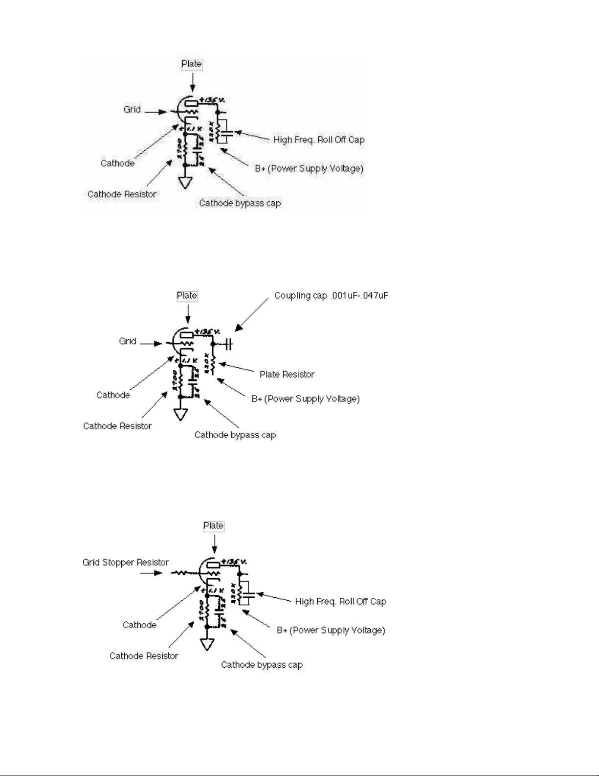
a very simplistic view of a tube stage.
As you can see above, in this tiny snippet of a tube schematic, the terms you commonly see are
there in this triode stage example.
Plate - the plate is usually connected to a plate resistor which is usually connected to the B+ or
power supply voltage. Typical Plate Resistor values are 100K, 150K, 220K. Larger values equal
more gain.
The Grid is where the signal enters the tube.
The Cathode is usually connected to a cathode resistor which usually goes to ground. The
cathode resistor, along with the Plate resistor, control the gain of the tube stage. Typical values
are anywhere from 100 ohms to 10K. Smaller values = more gain.
It is common to see a cathode bypass cap connected in parallel with the cathode resistor. By
altering the values of the cathode resistor and cathode bypass cap, it is possible to roll off
various degrees of bass with this triode stage. The cathode resistor and plate resistor control
the biasing of the tube. The cathode bypass cap also gives the stage more gain.
Sometime you see a capacitor in parallel with the plate resistor, much like the cathode resistor
bypass cap. It is usually a small value (i.e. .001uF) and it rolls off highs in the stage. Sometimes
you see a high frequency roll off cap as going from the plate pin to the cathode pin - 350pf-
>500pf in value.
Version 3.2 Page: 18
You will also see a coupling cap in between triode stages. The coupling cap controls the bass
and rolls off bass between stages and blocks DC from entering the next stage - which could
throw off the bias on the next tube stage. As usual, smaller values roll off more bass, larger
values retain more bass between stages.
Another modification you may see is a Grid Stopper Resistor, this can also control gain
between stages and also interacts with the tube to roll off highs. Values can be 1.5K->100K.
Larger values roll off more highs and reduce gain between stages. The Grid Stopper Resistor
works best when mounted directly or as close as possible to the grid pin.
"Complete" typical tube preamp stage:

Version 3.2 Page: 19
The grid ("leak") resistor, typically sets the impedance of the stage and biasing. It is interesting
because it and the previous stage's plate resistor form a voltage divider on the signal. What this
means to you is that the grid leak resistor can be used to control the level into the stage. Low
grid leak values will attenuate the signal into the tube stage. If you look at different tube amp
schematics, you can see where they control the level into the stage by using different values for
the grid leak resistor. There is a maximum value that you need to adhere to. Check the
datasheet for the tube you are using to see the typical value of the grid leak resistor. This
particular circuit is called cathode bias which you can read about here.
In summary, the cathode resistor, plate resistor and grid resistor, determine the biasing of the
tube stage. The cathode bypass cap controls the degree of bass reduction - generally 25uF
passes all frequencies - commonly used in Fender amps, 1uF less, .68uF is used in Marshall
amps. A capacitor can be placed in parallel with the plate resistor to roll off highs and you see
this in bass channels of amps sometimes. The plate receives the voltage from the power supply
through a plate resistor, the grid receives the AC signal as input and the cathode is grounded
through a cathode resistor.

Version 3.2 Page: 20
Input Jack Theory
~ from 18watt.com
This manual suits for next models
1
Table of contents
Other Trinity Amps Amplifier manuals

Trinity Amps
Trinity Amps Tramp User manual

Trinity Amps
Trinity Amps TRIWATT User manual

Trinity Amps
Trinity Amps TRIP TOP User manual

Trinity Amps
Trinity Amps Tube Effects Loop User manual

Trinity Amps
Trinity Amps Triton User manual

Trinity Amps
Trinity Amps OSD User manual

Trinity Amps
Trinity Amps TriFly User manual

Trinity Amps
Trinity Amps THOR User manual


