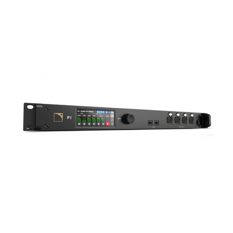
L-Acoustics L-ISA Processor II User manual

L-ISA Processor II
owner's manual (EN)

Document reference: L-ISA Processor II owner's manual (EN) version 1.0
Distribution date: March 22, 2022
© 2022 L-Acoustics. All rights reserved.
No part of this publication may be reproduced or transmitted in any form or by any means without the
express written consent of the publisher.

Contents
Safety................................................................................................................................................................ 6
Important safety instructions....................................................................................................................... 6
Symbols on the product.............................................................................................................................7
Introduction........................................................................................................................................................ 8
L-ISA Processor II...................................................................................................................................... 8
How to use this manual............................................................................................................................ 8
Revision history.........................................................................................................................................9
System components...........................................................................................................................................10
Technical description......................................................................................................................................... 12
Main features......................................................................................................................................... 12
Front and rear panels....................................................................................................................12
Signal processing....................................................................................................................................13
Signal inputs.................................................................................................................................13
Signal outputs............................................................................................................................... 14
DSP architecture............................................................................................................................14
USB ports...............................................................................................................................................15
Power supply..........................................................................................................................................15
Monitoring and control............................................................................................................................15
User interface............................................................................................................................... 15
Remote control network..................................................................................................................15
Inspection and preventive maintenance...............................................................................................................16
How to do preventive maintenance.......................................................................................................... 16
External structure.....................................................................................................................................16
Cleanness...............................................................................................................................................17
Normal start-up sequence........................................................................................................................ 17
Network functionalities and rmware........................................................................................................17
Installation........................................................................................................................................................18
Mounting................................................................................................................................................18
Ventilation.............................................................................................................................................. 19
Audio and network cabling..................................................................................................................... 20
Connection panels.........................................................................................................................20
Network conguration................................................................................................................... 21
Connecting to AC mains......................................................................................................................... 22
Electrical specications.................................................................................................................. 22
Power cord...................................................................................................................................22
3

Plugging to AC mains................................................................................................................... 23
Power consumption........................................................................................................................23
Operation........................................................................................................................................................ 24
Powering on/off..................................................................................................................................... 24
Front panel LEDs.....................................................................................................................................24
CONTROL.................................................................................................................................... 24
STATUS........................................................................................................................................ 25
SYNC.......................................................................................................................................... 25
WORD.........................................................................................................................................25
IN/OUT....................................................................................................................................... 26
Emergency USB key................................................................................................................................ 26
Preparing and updating the emergency USB key..............................................................................26
Rebooting L-ISA Processor II using the emergency USB key................................................................ 27
Other operations.....................................................................................................................................27
Corrective maintenance..................................................................................................................................... 28
Introduction.............................................................................................................................................28
Presentation.................................................................................................................................. 28
Equipment and tools......................................................................................................................28
Screws and fasteners repair kit...................................................................................................... 29
Troubleshooting and diagnosis................................................................................................................. 29
Power issues................................................................................................................................. 29
Interface issues..............................................................................................................................29
Network issues..............................................................................................................................30
Sound issues.................................................................................................................................30
L-ISA Processor II exploded view.............................................................................................................. 32
External modules...........................................................................................................................32
Disassembly and Reassembly procedures.................................................................................................. 33
D/R - Grill....................................................................................................................................33
D/R - Handles.............................................................................................................................. 34
D/R - Front brackets......................................................................................................................35
D/R - Rear brackets...................................................................................................................... 36
D/R - Rear brackets support screws................................................................................................ 37
D/R - Rear connectors brackets...................................................................................................... 38
Specications................................................................................................................................................... 39
General................................................................................................................................................. 39
Inputs and outputs...................................................................................................................................39
Remote control and monitoring.................................................................................................................40
Physical data..........................................................................................................................................40
4

Appendix A - Glossary..................................................................................................................................... 42
Appendix B - Approvals....................................................................................................................................43
5

Safety
Safety
Important safety instructions
Inspect the product before operation.
If any sign of defect or damage is detected, immediately withdraw the product from use for maintenance.
Perform preventive maintenance at least once a year.
Refer to the preventive maintenance section for a list of actions and their periodicity.
Insufcient upkeep of the product can void the warranty.
Verify the electrical conformity and compatibility of the mains supply.
Only connect the product to an AC power outlet rated 100-240 V, 50-60 Hz.
The product draws 150 W (typical).
WARNING: The product is of Class 1 construction and shall be connected to a mains socket outlet with a
Protective Earth connection.
When the product is used in a three-phase circuit, verify the electrical conformity and
compatibility of the three-phase circuit.
Verify that the three phases work, and balance the loads between the three phases.
Verify that the neutral and earth work.
Never try to emulate a 230 V circuit connecting an apparatus to two live wires of a 120 V three-phase circuit.
Never try to emulate a 200 V circuit connecting an apparatus to two live wires of a 100 V three-phase circuit.
Never incorporate equipment or accessories not approved by L-Acoustics.
Read all the related PRODUCT INFORMATION documents shipped with the products before
exploiting the system.
Intended use
This system is intended for use by trained personnel for professional applications.
As part of a continuous evolution of techniques and standards, L-Acoustics reserves the right
to change the specications of its products and the content of its documents without prior
notice.
Check www.l-acoustics.com on a regular basis to download the latest document and software updates.
Beware of sound levels.
Do not stay within close proximity of loudspeakers in operation.
Loudspeaker systems are capable of producing very high sound pressure levels (SPL) which can instantaneously
lead to permanent hearing damage to performers, production crew and audience members. Hearing damage
can also occur at moderate level with prolonged exposure to sound.
Check the applicable laws and regulations relating to maximum sound levels and exposure times.
Do not use the product outside its operating temperature range.
The product operates at a room temperature between -5 °C / 23 °F and 50 °C / 122 °F.
Do not expose the product to direct sun.
Long term exposure to extreme conditions may damage the product.
For more information, refer to the Products weather protection document, available on the website.
Only use the product in a conformed electro-magnetic environment (EN55035 standard).
Avoid radio interference.
This product has been tested and complies with the limits indicated in the EMC directive (Electro Magnetic
Compatibility). These limits are designed to provide reasonable protection against harmful interference from
electrical equipment, but it cannot be guaranteed that interference will never occur.
6 L-ISA Processor II owner's manual (EN) version 1.0

Safety
Product disconnection
To completely disconnect this product from the mains, disconnect all power supply cord plugs from the mains
socket outlets.
Power supply cord and socket accessibility
The main plug of the power supply cord shall remain easily accessible.
The mains socket outlet shall be easily accessible.
Risk of start-up sequence failure
The HDMI port is only required for maintenance operations.
Do not use the HDMI port during normal operation of the processor.
Read the maintenance section of this document before servicing the product.
Contact L-Acoustics for advanced maintenance.
Any unauthorized maintenance operation will void the product warranty.
Shipping
Use the original packaging for shipping the product, unless it is mounted in a rack with the front and rear panels
xed to the rack, as described in this manual.
Symbols on the product
Explanation of graphical symbols
The lightning ash with arrowhead symbol within an equilateral triangle is intended to alert the user
to the presence of uninsulated "dangerous voltage" within the product's enclosure that may be of
sufcient magnitude to constitute a risk of electric shock to persons.
The exclamation point within an equilateral triangle is intended to alert the user to the presence of
important operating and maintenance instructions in the literature accompanying the product.
Do not open unless authorized. This symbol indicates the presence of electrical shock hazards. It also
indicates that no maintenance performed by the end user requires access to internal components.
This marking indicates that this product should not be disposed of with other household waste
throughout the EU. To prevent possible harm to the environment or human health from uncontrolled
waste disposal, recycle it responsibly to promote the sustainable reuse of material resources. To return
your used device, please use the return and collection systems or contact the retailer where the product
was purchased. They can take this product for environmentally safe recycling.
The device can be supplied by multiple sources of power. Disconnect all power supply cord plugs from
the mains socket outlets to fully disconnect this product from the mains.
L-ISA Processor II owner's manual (EN) version 1.0 7

Introduction
Introduction
L-ISA Processor II
L-ISA Processor II is a hardware solution dedicated to real-time spatial audio processing. It provides state of the art object-
based mixing to any immersive audio production from intimate installations to the largest tours. The processor has been
entirely redesigned for added robustness and greater resources, now offering 128 inputs and up to 128 outputs using
Milan-AVB and MADI protocols.
L-ISA Processor II can process up to 96 objects with spatial processing parameters (pan, width, distance, elevation) and
the patent-pending room engine. Improving upon its predecessor, these objects can be rendered to up to 128 outputs at
96 kHz. To adapt to any project or production size and budget, L-ISA Processor II introduces a scalable licensing model
that offers license packs with 16, 32, 64 and 128 outputs, which can be upgraded as needed.
The re-engineered chassis has been ruggedized with robust mechanics and locking connectors, and includes two
redundant universal power supplies. When required, a second processor can be used in mirror mode for further
redundancy. As a Milan-compliant device, L-ISA Processor II also ensures reliability for audio distribution with seamless
Milan network redundancy for all AVB streams.
L-ISA Processor II is remotely controlled and monitored using the L-ISA Controller software.
How to use this manual
The L-ISA Processor II owner's manual is intended for all actors involved in the system design, implementation, preventive
and corrective maintenance of the L-ISA Processor II product. It must be used as follows:
1. Read the technical description for an overview of all product elements, their features, and their compatibilities.
•Technical description (p.12)
2. Before installing the product, perform mandatory inspections and functional checks.
•Inspection and preventive maintenance (p.16)
3. To deploy the product, follow the step-by-step installation instructions and refer to the cabling schemes.
•Installation (p.18)
•Audio and network cabling (p.20)
4. To congure the settings and parameters of the product, follow the step-by-step operation instructions.
•Operation (p.24)
The Corrective maintenance (p.28) section contains the operations authorized for the end user.
Performing another operation exposes to hazardous situations.
For advanced maintenance, contact your L-Acoustics representative.
As part of a continuous evolution of techniques and standards, L-Acoustics reserves the right to
change the specications of its products and the content of its documents without prior notice.
Check www.l-acoustics.com on a regular basis to download the latest document and software updates.
8 L-ISA Processor II owner's manual (EN) version 1.0

Introduction
Contact information
For information on advanced corrective maintenance:
• contact your Certied Provider or your L-Acoustics representative
• for Certied Providers, contact the L-Acoustics customer service: customer.ser[email protected] (EMEA/APAC),
laus.ser[email protected] (Americas).
Symbols
The following symbols are used in this document:
This symbol indicates a potential risk of harm to an individual or damage to the product.
It can also notify the user about instructions that must be strictly followed to ensure safe installation or operation of
the product.
This symbol indicates a potential risk of electrical injury.
It can also notify the user about instructions that must be strictly followed to ensure safe installation or operation of
the product.
This symbol noties the user about instructions that must be strictly followed to ensure proper installation or
operation of the product.
This symbol noties the user about complementary information or optional instructions.
Revision history
version number publication date modication
1.0 Mar. 2022 Initial version.
L-ISA Processor II owner's manual (EN) version 1.0 9

System components
System components
Processor
L-ISA Processor II L-ISA multichannel audio processor
Networking
LS10 AVB switch
Cables
DOE cables Dual AVB Network cable CAT6A, etherCON (black = primary network, red = secondary
network)
Come in different sizes: DOE2 (2 m / 6.6 ft), DOE45 (45 m / 147.6 ft), and DOE100 (100
m / 328.1 ft)
In AVB networks, for lengths greater than 80 m / 262 ft from the processor to the listeners, add LS10 as a relay
in between.
Software applications
L-ISA Controller Software suite for object-based mixing and remote control of L-ISA processors
Refer to the L-ISA Controller help.
System component illustrations
Cables
2 m / 45 m / 100 m
red
black
red
black
6.6 ft / 147.6 ft / 328.1 ft
DOE cables
Software applications
L-ISA Controller
10 L-ISA Processor II owner's manual (EN) version 1.0

System components
Network switch
LS10
L-ISA Processor II owner's manual (EN) version 1.0 11

Technical description
Main features
Front and rear panels
1 2 3 4 5 6 7 8 9 10
1power LED 6input LED
2control network LED 7output LED
3status LED 8USB 3.1 port
4clock synchronization LED 91/4 inch stereo headphone jack
5word clock LED 10 power button
1 2 3 5 6
4 8 11 127 10
9
1backup system key holder* 71 Gb/s Ethernet etherCON I/O connectors for AVB
network
2HDMI port (for maintenance use only) 81 Gb/s Ethernet etherCON I/O connector for remote
control
3USB 3.1 ports (for maintenance use only) 9female XLR AES/EBU input connector
4V-Lock compatible IEC C13 power connectors 10 male XLR AES/EBU output connector
5MADI input BNC connectors 11 word clock input BNC connector
6MADI output BNC connector 12 word clock output BNC connector
*The key holder port is tted with a 32 GB USB 3.1 ash drive for backup in case of hard drive failure.
Refer to Emergency USB key (p.26).
12 L-ISA Processor II owner's manual (EN) version 1.0

Technical description
Signal processing
L-ISA Processor II has no SRC capabilities. Therefore, the input audio streams sample rate must match the DSP
sample rate, and the output streams match the DSP sample rate.
Supported sample rates
44.1 kHz 48 kHz 96 kHz
IN 192 channels 96 channels
MADI OUT 64 channels 32 channels
IN
AES/EBU OUT yes
IN
Milan-AVB OUT N/A yes
Headphones OUT yes
Signal inputs
L-ISA Processor II features three BNC MADI input connectors and two Ethernet ports allowing it to process up to 128
inputs selected from:
• 64 AVB channels (8 redundant streams of 8 channels) and 96 MADI channels at 96 kHz.
• 64 AVB channels and 192 MADI channels at 48 kHz.
To maintain the phase relationship between inputs into the L-ISA Processor II, it is recommended not to mix MADI
and AVB channels from the same device due to latency differences of the stream formats (>1 ms).
In addition, L-ISA Processor II features one XLR input connector capable of retrieving two AES/EBU channels.
MADI
L-ISA Processor II can receive up to 192 channels at 44.1 kHz / 48 kHz or up to 96 channels at 96 kHz, using the three
MADI input BNC connectors on the rear panel.
AES/EBU
L-ISA Processor II can receive two AES/EBU digital audio channels at 44.1 kHz, 48 kHz, or 96 kHz using the AES/EBU
input connector on the rear panel.
The connector is a female XLR3.
Milan-AVB
Eight redundant AVB streams of up to eight channels may be connected to L-ISA Processor II, for a total of 64 AVB
channels. One CRF stream may also be connected to L-ISA Processor II.
Each Ethernet port uses a high speed data transfer protocol up to 1 Gb/s and supports the Milan AAF PCM32 stream
format, with stream frequencies of 48 kHz or 96 kHz.
L-ISA Processor II owner's manual (EN) version 1.0 13

Technical description
Signal outputs
L-ISA Processor II features a dedicated BNC MADI output connector and two Ethernet ports allowing the distribution of up
to 16, 32, 64, or 128 outputs (depending on the license) that can be received from 128 redundant Milan-AVB channels
(16 streams of up to 8 channels) and 32 MADI channels at 96 kHz or 64 MADI channels at 48 kHz.
L-ISA Processor II has a default capability of 16 audio outputs. This capability can be increased with a SW Output
Pack. For more information, refer to www.l-acoustics.com.
Among the 128 outputs, up to 64 outputs can be L-ISA speakers.
In addition, L-ISA Processor II features one XLR connector capable of distributing two AES/EBU digital routing output
signals.
MADI
L-ISA Processor II can distribute up to 64 channels at 44.1 kHz / 48 kHz or up to 32 channels at 96 kHz, using the
MADI output BNC connector on the rear panel.
AES/EBU
L-ISA Processor II can distribute two AES/EBU digital routing signals at 44.1 kHz, 48 kHz, or 96 kHz using the AES/EBU
output connector on the rear panel.
The connector is a male XLR3.
Milan-AVB
L-ISA Processor II can distribute up to 16 redundant streams of up to 8 channels, for a total of 128 AVB channels.
L-ISA Processor II can also distribute one CRF stream, unless all 16 stream outputs are already being used for AVB
channels distribution. In this case, one of the stream output must be dedicated to the CRF stream.
Each connector uses a high speed data transfer protocol up to 1 Gb/s and supports the Milan AAF PCM32 stream
format, with stream frequencies of 48 kHz or 96 kHz.
Other
L-ISA Processor II features a 1/4 inch stereo headphone jack.
An HDMI port is available for maintenance purposes.
Risk of start-up sequence failure
The HDMI port is only required for maintenance operations.
Do not use the HDMI port during normal operation of the processor.
DSP architecture
1 ×
ROUTINGS
DOWN MIX
AUX
INPUT
ROUTING
L-ISA
SPEAKERS
BINAURA L
ROOM
ENGINE
SPATIAL
PROCESSING
SPATIAL
FILLS
A ES/EBU
HEADPHON ES
A ES/EBU
OUTPUT ROUTING
AVB
MADI
BNC 1
MADI
BNC 2
MADI
BNC 3
MADI
BNC
AVB
OUTPUTSINPUTS
Multicore floating point processing 44.1 (MADI and AES/EBU only), 48 or 96 kHz sampling rates.
Latency = 3.2 ms
DSP
128 channels Up to 128 channels
(mirrored)
14 L-ISA Processor II owner's manual (EN) version 1.0

Technical description
USB ports
L-ISA Processor II features three USB 3.1 ports.
The USB port on the front panel and the two USB ports on the rear panel can be used to connect the emergency USB key,
or for maintenance purposes.
The KEY HOLDER USB port is not functional and is for storage purposes only.
If a connected device draws more than 900 mA / 5 V, the USB ports stop working.
The integrated USB ports cannot be used to charge a device.
If the USB ports stop working, disconnect the device and power cycle L-ISA Processor II.
Power supply
L-ISA Processor II relies on a redundant universal Switched Mode Power Supply (SMPS) suitable for mains from 100 V AC
- 240 V AC (± 10%), 50 Hz - 60 Hz, 150 W.
Monitoring and control
User interface
The LED display provides real-time monitoring functionalities:
• power
• control
• status
• clock synchronization
• word clock
• input signal presence / clipping
• output signal presence / clipping
Refer to section Operation (p.24) for detailed operating instructions.
Remote control network
The computer running L-ISA Controller and the processors are connected with industry standard CAT5e U/FTP cables (or
higher category) tted with RJ45 connectors.
In AVB networks, for lengths greater than 80 m / 262 ft from the processor to the listeners, add LS10 as a relay
in between.
L-ISA Processor II connects to the L-ISA Controller network via the CONTROL Ethernet etherCON I/O socket located on its
rear panel.
L-ISA Processor II is compatible with OSC for third party control tools.
Refer to the L-ISA Controller Help for detailed operating instructions.
L-ISA Processor II owner's manual (EN) version 1.0 15

Inspection and preventive maintenance
How to do preventive maintenance
Inspect the product periodically as indicated, and after any corrective maintenance operation.
Structure and cleanness
Before and after each deployment (touring applications), or at least once a month (xed installations):
•External structure (p.16)
•Cleanness (p.17)
Functionalities
At least once a year:
•Normal start-up sequence (p.17)
•Network functionalities and rmware (p.17)
External structure
The indicates a visual inspection.
side brackets, front handles, and rear
brackets are present and not damaged
front grills are clean and not damaged
see also Cleanness (p.17)
front connectors, chassis, and LEDs are not damaged rear connectors are not damaged
rear grill is clean and not damaged
emergency USB key is present in KEY HOLDER port
16 L-ISA Processor II owner's manual (EN) version 1.0

Inspection and preventive maintenance
Cleanness
Equipment
• air blower
Procedure
Clean the processor through the front grill with an air blower.
Normal start-up sequence
Procedure
1. Plug the processor to mains.
2. Power on the processor.
3. Check that the LEDs light up during the start-up sequence.
Network functionalities and rmware
Equipment
• computer with L-ISA Controller version 2.3.x minimum
• CAT5e U/FTP cable
Procedure
1. Connect the CONTROL Ethernet port of the processor to an Ethernet port of a computer running L-ISA Controller.
Use the CAT5e U/FTP cable.
2. Run L-ISA Controller.
3. Check that the processor is detected as available in the Processors view.
Refer to the L-ISA Controller Help.
4. Check that all processors in the system run the same version of the rmware, and that it matches the version of L-ISA
Controller in use.
5. Update L-ISA Controller and the rmware of the processor to the latest versions.
6. Update the rmware on the emergency USB key to the latest version.
Refer to Emergency USB key (p.26).
L-ISA Processor II owner's manual (EN) version 1.0 17

Installation
Installation
Mounting
The L-ISA Processor II is three rack units high (3U) and can be mounted in an EIA-standard 19” rack using the four points
on the front panel. Use the xing material provided by the rack manufacturer to mount L-ISA Processor II to the rack front
rails.
L-ISA Processor II dimensions
483 mm / 19 in 458 mm / 18 in 465 mm / 18.3 in
433 mm / 17 in
133.35 mm / 5.25 in 121 mm / 4.7 in
24.3 mm / 1 in
Risk of damaging L-ISA Processor II
L-ISA Processor II should be rear supported in addition to the front panel mounting.
Use the rear brackets provided with L-ISA Processor II.
Any mechanical damage to L-ISA Processor II used without rear support is not covered by warranty.
L-ISA Processor II with rear rack support brackets
max. 515 mm / 20.3 in
18 L-ISA Processor II owner's manual (EN) version 1.0

Installation
Ventilation
To maintain moderate operating temperatures, L-ISA Processor II is equipped with fans and openings providing front to
rear airow.
Ventilation instructions
Install the processor in an open area so that the front and rear panels are located at a minimum distance of
30cm / 12 in from any external object or structure.
Ensure that the front and rear grills are clean and dirt free.
Do not block the front and rear ventilation grills.
Ventilation when rack-mounted
Do not block the ventilation grills with front or back panels or doors. If not possible, use a forced-ventilation
system.
When stacking more than one processor in a rack, mount them directly on top of each other or close any open
space in the rack with blank panels.
L-ISA Processor II owner's manual (EN) version 1.0 19

Installation
Audio and network cabling
Connection panels
L-ISA Processor II features input, output, and AVB connectors on its rear panel for audio and network connection.
Audio and network connectors
1
3
2
6 74 5
1. MADI inputs
2. MADI output
3. Ethernet connectors for AVB networks and remote control
4. AES/EBU input
5. AES/EBU output
6. Word Clock input
7. Word Clock output
The AES/EBU XLR3 connectors are wired according to IEC 60268-12:
• pin 1: shield
• pin 2: + signal
• pin 3: - signal
BNC MADI connectors
The BNC input connectors can receive 192 inputs at 44.1 kHz / 48 kHz, or 96 inputs at 96 kHz.
The BNC output connector can send 64 outputs at 44.1 kHz / 48 kHz, or 32 outputs at 96 kHz.
AES/EBU connectors
The AES/EBU input connector can receive two digital input signals.
The AES/EBU output connector can send two digital output signals.
Supported digital input format
Standards: AES/EBU (AES3) or electrical S/PDIF (IEC 60958 Type II)
Sampling frequency: 44.1 kHz, 48 kHz, or 96 kHz
Word length: 24 bits
Ethernet connectors
Use the CONTROL etherCON connector for the remote control of L-ISA Processor II using L-ISA Controller.
The PRIMARY and SECONDARY etherCON connectors can be used to create two redundant Milan-AVB networks.
20 L-ISA Processor II owner's manual (EN) version 1.0
Table of contents
Other L-Acoustics Computer Hardware manuals
Popular Computer Hardware manuals by other brands

Cypress Semiconductor
Cypress Semiconductor CY7C1324H Specification sheet

Cypress
Cypress CY3273 quick start guide

Silicon Laboratories
Silicon Laboratories Stepper Machine user guide

Emerson
Emerson Dixell iChill ICX207D Quick reference guide

Renesas
Renesas R0E521258CFJ00 user manual

Advantech
Advantech ADAM CPU 821 Series manual