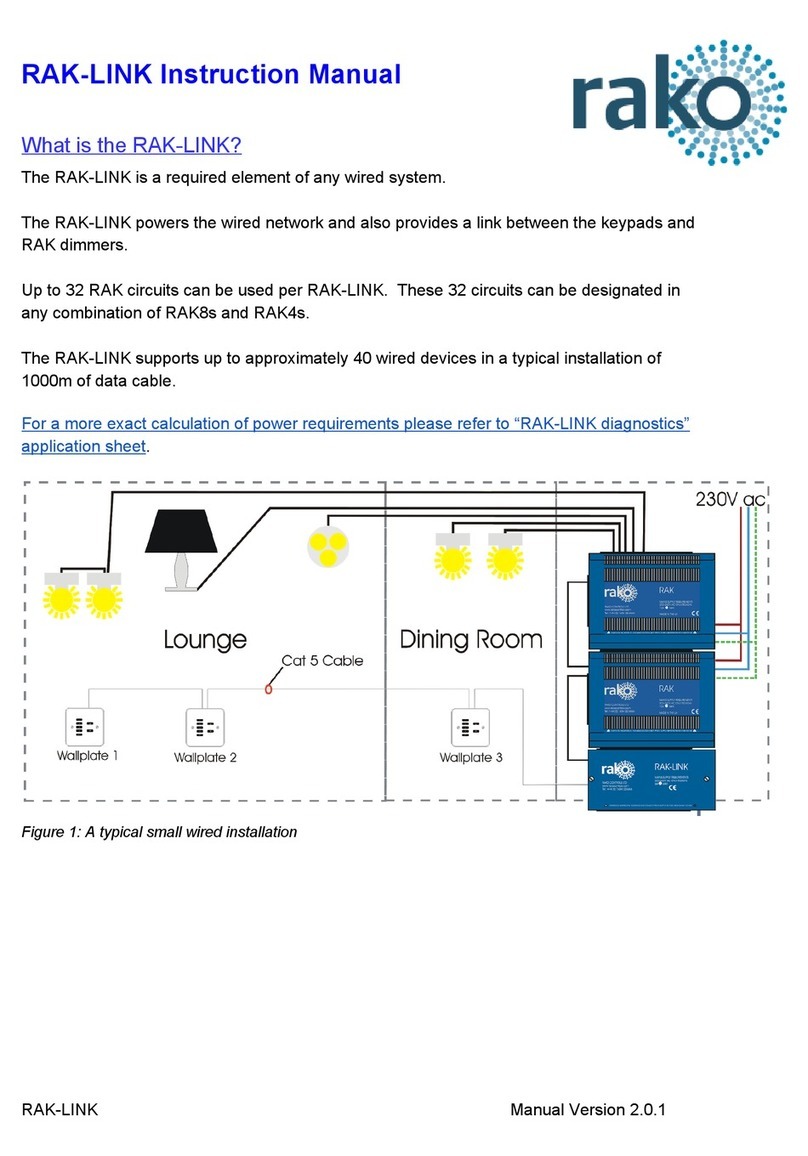
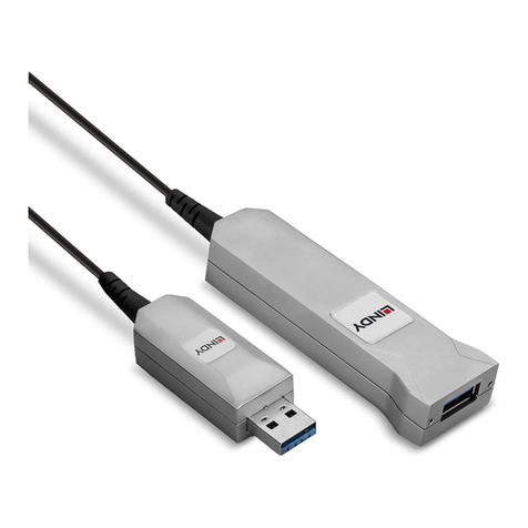
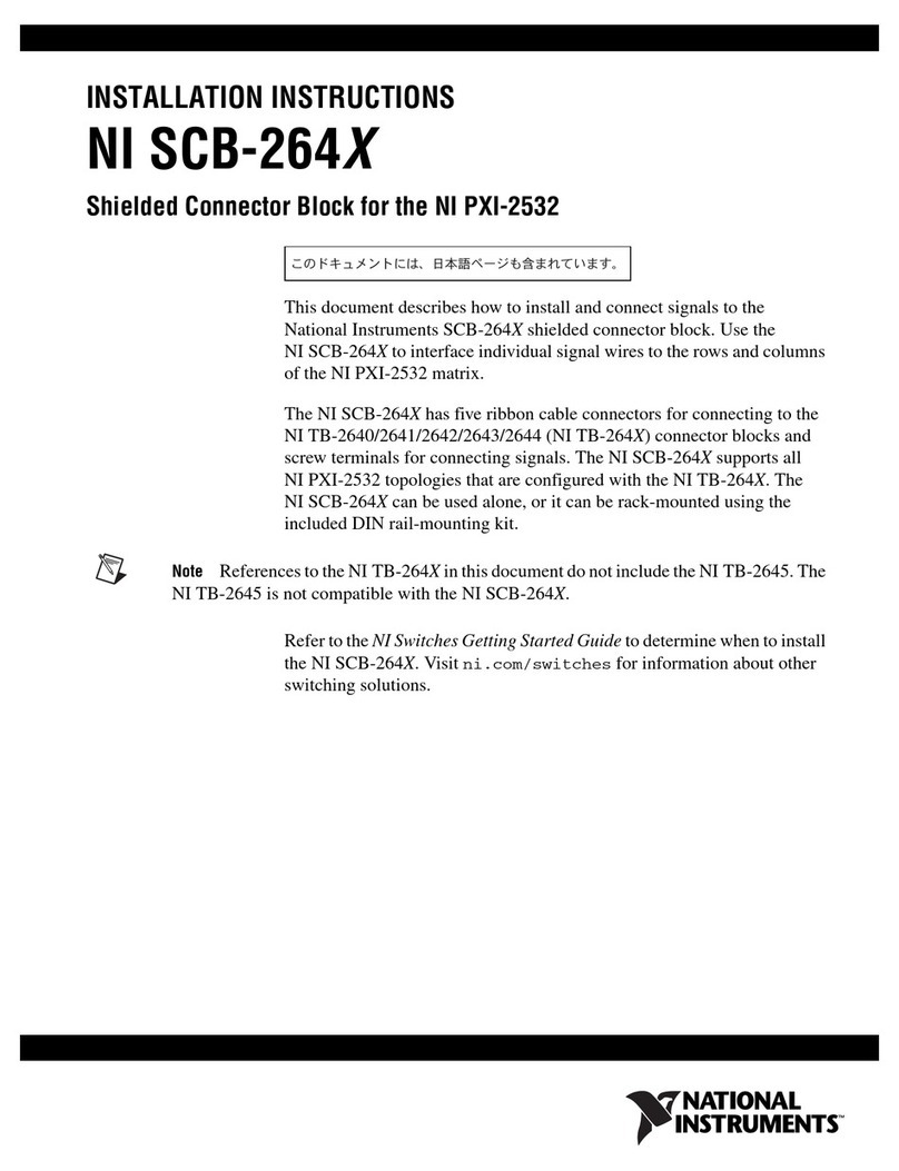
l-com DGBH15FT User manual

FIELDTERMINATIONINSTRUCTIONSFORA
DGBH15FTCONNECTOR
STEP1:
TrimbackSVGAcabletoexposeconductorsasshownbelow.
CenterConductor
OuterConductor
(Shield)
(3)Coax:
Blue,Red,Green
(4)TwistedPair
Conductors
(2)Conductors
(1)DrainWire
3inchesapproximately
INTRODUCTION:
TheDGBH15FTconnectorisdesignedforusewith
SVGAcableshaving(3)coaxlines(R,G,B)and(4)
twistedpairlineswith(2)conductorlinesanda
drainwire.NumerousconfigurationsofSVGA
cablesexist,signalnamesaregivento
accommodatethevariousSVGAcabletypeswith
differentconductorcolors.
45BeechwoodDrive NorthAndover,MA01845
Tel:800-343-1455 Fax:978-689-9484or978-685-6467
E-mail:sales@L-com.com Web:www.L-com.com
45BeechwoodDrive NorthAndover,MA01845
Tel:800-343-1455 Fax:978-689-9484or978-685-6467
E-mail:sales@L-com.com Web:www.L-com.com
45BeechwoodDrive NorthAndover,MA01845
Tel:800-343-1455 Fax:978-689-9484or978-685-6467
E-mail:sales@L-com.com Web:www.L-com.com
45BeechwoodDrive NorthAndover,MA01845
Tel:800-343-1455 Fax:978-689-9484or978-685-6467
E-mail:sales@L-com.com Web:www.L-com.com
50 High Street, West Mill, 3rd floor, Suite #30, North Andover, MA 01845
Tel: 800-343-1455 Fax: 978-689-9484 or 978-685-6467
50 High Street, West Mill, 3rd floor, Suite #30, North Andover, MA 01845
Tel: 800-343-1455 Fax: 978-689-9484 or 978-685-6467

©L-com,Inc. Allrightsreserved. DGBH15FT-INS REV.09/06
45 Beechwood Drive • N. Andover, MA 01845 • Web: www.L-com.com • E-mail: sales@L-com.com
Tel: 800-343-1455 • Fax: 978-689-9484 or 978-685-6467
©L-com,Inc. Allrightsreserved. DGBH15FT-INS REV.09/06
45 Beechwood Drive • N. Andover, MA 01845 • Web: www.L-com.com • E-mail: sales@L-com.com
Tel: 800-343-1455 • Fax: 978-689-9484 or 978-685-6467
©L-com,Inc. Allrightsreserved. DGBH15FT-INS REV.09/06
45 Beechwood Drive • N. Andover, MA 01845 • Web: www.L-com.com • E-mail: sales@L-com.com
Tel: 800-343-1455 • Fax: 978-689-9484 or 978-685-6467
©L-com,Inc. Allrightsreserved. DGBH15FT-INS REV.09/06
45 Beechwood Drive • N. Andover, MA 01845 • Web: www.L-com.com • E-mail: sales@L-com.com
Tel: 800-343-1455 • Fax: 978-689-9484 or 978-685-6467
STEP2:
Identifyconductortoappropriatesignalnameper
pinouttable.Thesignalnamesarealsoetchedonthe
DGBH15FTPCBforreference.Note:Duetothewide
varietyofSVGAcable,thereisnostandardcolorcode
fortheconductorsotherthanthecoaxialRed,Green,
Blue.Theonlycertainwaytoidentifycorrect
conductoristoperformacontinuitytest.
STEP 3:
Insertcoaxialcenterconductorsandshieldsas
wellasconductorsintoappropriateslotsof
terminalboardbysignalnameinaccordance
with SVGA pinout table and etched signal
namesonthePCB.Tightenscrewstosecure.
STEP4:
Attachthecompletedassemblyto
mountingsurface.
SVGA PINOUT TABLE
PIN SIGNAL WIRE
1 RED COAX CC
2 GREEN COAX CC
3 BLUE COAX CC
4 ID BIT 2 TP 1
5 GROUND TP1
6 RED SHIELD COAX SHLD
7 GREEN SHIELD COAX SHLD
8 BLUE SHIELD COAX SHLD
9 DDV +5V COND 1
10 SYNC RTN TP 3/4
11 ID BIT 0 TP 2
12 ID BIT 1 TP 2
13 HORZ SYNC COND 2
14 VER SYNC TP 3
15 ID BIT 3 TP 4
16 SHELL DRAIN WIRE
STEP2:
Identifyconductortoappropriatesignalnameper
pinouttable.Thesignalnamesarealsoetchedonthe
DGBH15FTPCBforreference.Note:Duetothewide
varietyofSVGAcable,thereisnostandardcolorcode
fortheconductorsotherthanthecoaxialRed,Green,
Blue.Theonlycertainwaytoidentifycorrect
conductoristoperformacontinuitytest.
STEP 3:
Insertcoaxialcenterconductorsandshieldsas
wellasconductorsintoappropriateslotsof
terminalboardbysignalnameinaccordance
with SVGA pinout table and etched signal
namesonthePCB.Tightenscrewstosecure.
STEP4:
Attachthecompletedassemblyto
mountingsurface.
SVGA PINOUT TABLE
PIN SIGNAL WIRE
1 RED COAX CC
2 GREEN COAX CC
3 BLUE COAX CC
4 ID BIT 2 TP 1
5 GROUND TP1
6 RED SHIELD COAX SHLD
7 GREEN SHIELD COAX SHLD
8 BLUE SHIELD COAX SHLD
9 DDV +5V COND 1
10 SYNC RTN TP 3/4
11 ID BIT 0 TP 2
12 ID BIT 1 TP 2
13 HORZ SYNC COND 2
14 VER SYNC TP 3
15 ID BIT 3 TP 4
16 SHELL DRAIN WIRE
STEP2:
Identifyconductortoappropriatesignalnameper
pinouttable.Thesignalnamesarealsoetchedonthe
DGBH15FTPCBforreference.Note:Duetothewide
varietyofSVGAcable,thereisnostandardcolorcode
fortheconductorsotherthanthecoaxialRed,Green,
Blue.Theonlycertainwaytoidentifycorrect
conductoristoperformacontinuitytest.
STEP 3:
Insertcoaxialcenterconductorsandshieldsas
wellasconductorsintoappropriateslotsof
terminalboardbysignalnameinaccordance
with SVGA pinout table and etched signal
namesonthePCB.Tightenscrewstosecure.
STEP4:
Attachthecompletedassemblyto
mountingsurface.
SVGA PINOUT TABLE
PIN SIGNAL WIRE
1 RED COAX CC
2 GREEN COAX CC
3 BLUE COAX CC
4 ID BIT 2 TP 1
5 GROUND TP1
6 RED SHIELD COAX SHLD
7 GREEN SHIELD COAX SHLD
8 BLUE SHIELD COAX SHLD
9 DDV +5V COND 1
10 SYNC RTN TP 3/4
11 ID BIT 0 TP 2
12 ID BIT 1 TP 2
13 HORZ SYNC COND 2
14 VER SYNC TP 3
15 ID BIT 3 TP 4
16 SHELL DRAIN WIRE
L-com Global Connectivity | 50 High St., West Mill, 3rd floor, Suite #30 | North Andover, MA 01845 | USA
© L-com, Inc. All Rights Reserved. L-com Global Connectivity and the L-com Logo are registered marks.
Toll Free Ordering and Technical Support: 1-800-343-1455 Visit our website at www.L-com.com
Popular Cables And Connectors manuals by other brands
Honeywell
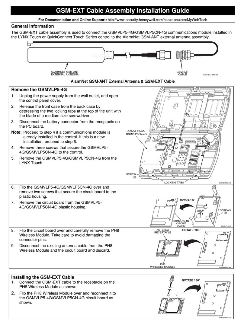
Honeywell GSM-EXT Assembly Installation Guide
Telegärtner
Telegärtner H02051A026 Series installation instructions

Weh
Weh TW102 operating instructions
PCB Piezotronics
PCB Piezotronics 037P50 Installation and operating manual
SIIG
SIIG USB 3.0 Quick installation guide

Philips
Philips SWA5510 Specifications
